Week 1 Challenge
1.Name the three ways by which you can create a model.
The three ways by which we can create a model are as given below:-
1. Analytical model
2. Physical model
3. Building planner model

2. Explain the coordinate system adopted in STAAD Pro software.
The coordinate system adopted in STAAD.Pro software namely X, Y and Z axis. The basic commonly coordinate system adopted in STAAD.Pro is:-
a) Local axis:- Local axis is variable in nature.
b) Global axis:- Global axis is fixed which has three coordinates namely global x, global y and global z axis
Basically STAAD.Pro uses a conventional structural system and in this case height of the structure refers to global Y axis
3. Explain the difference between Fixed and Fixed But conditions.
Fixed condition:- Fixed condition is the condition where all the three degree of freedom that is horizontal or vertical or fixed are been completely restrained
Fixed but conditions:- The Fixed But support condition is used to allow the user to define which degrees of freedom of a node are free and which are fixed.
4. How will you assign Unit system to a .std model file?
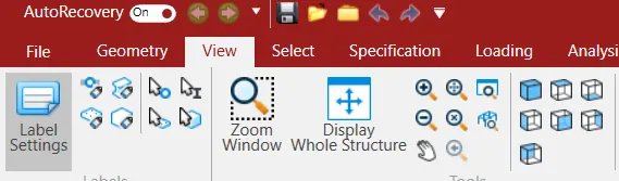
Go to view > Select different view position
The different types of views are as given below:-
a) Isometric view
b) Top view
c) Bottom view
d) Left view
e) Front view
f) Right view
g) Back view
1. Create a STAAD Model with the following Specification
a. A beam of span 16m
b. Support : Fixed on one end and Roller support(Horizontal) on the other end
c. A point load of 50 kN at the mid-point
d. Draw SFD and BMD using software
AIM:- To create a STAAD model with the following specification:-
a) A beam of span 16 m
b) Support : Fixed on one end and roller support on the other end
c) A point load of 50 KN at the mid-point
d) Draw SFD and BMD using software.
INTRODUCTION :- All the steps are going to be explained with step by step procedure.
PROCEDURE:-
- Open STAAD. Pro Connect Edition software
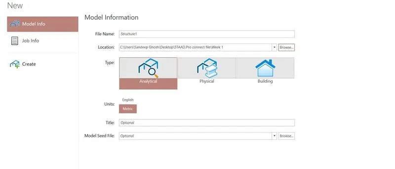
- Select file name and save it to the specified folder
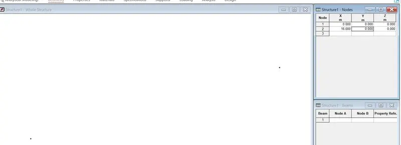
- Create node by using specified distance 16 m
- Create beam element by using geometry option
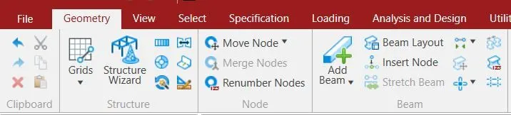
- Draw it by using connecting two nodes
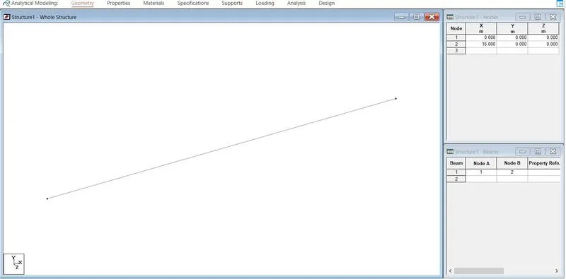
- Go to property section to define its property
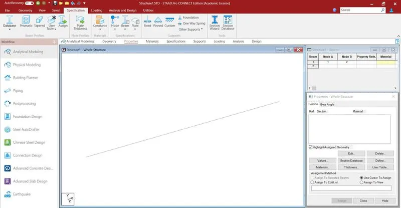
- Define its property by using specified dimension such as depth and width is equal to 0.45 m for concrete material
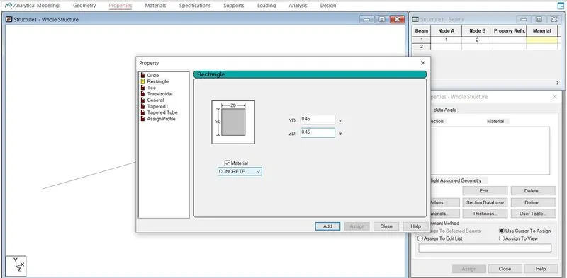
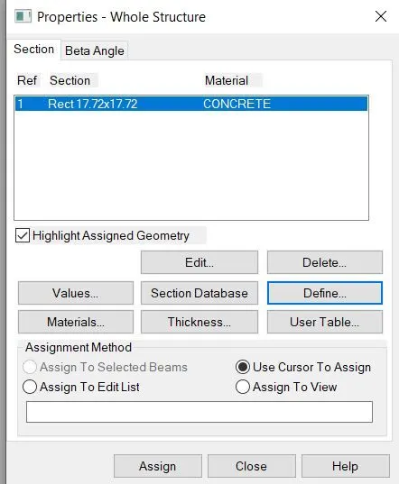
- Assign it
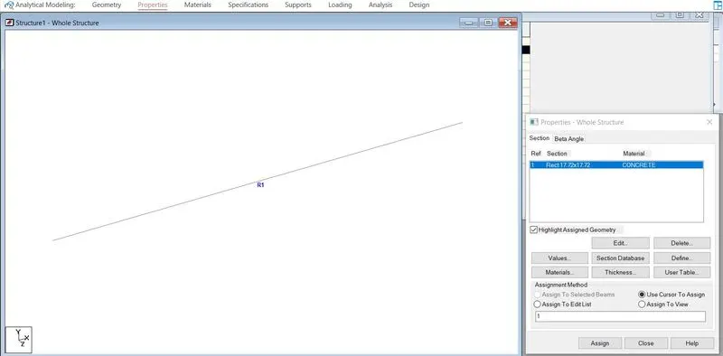
- Assign the support specifications by using fixed on one end and roller support
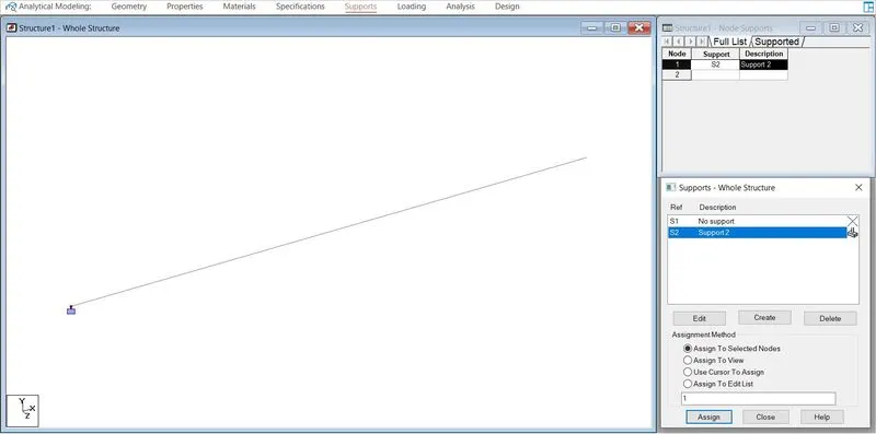
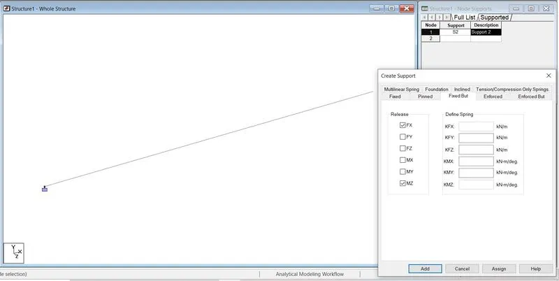
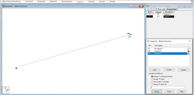
- Define load cases by adding dead load and live load
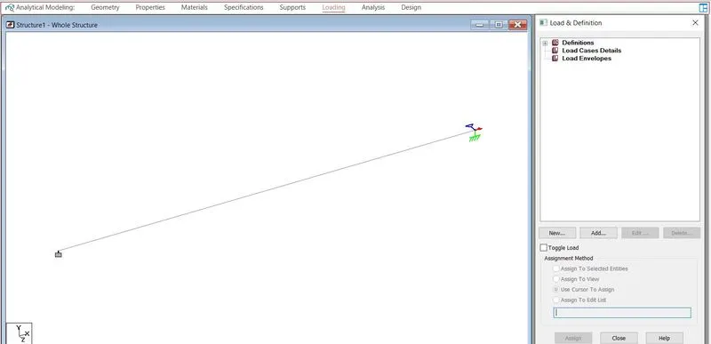
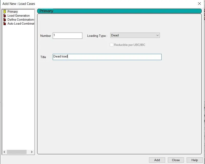
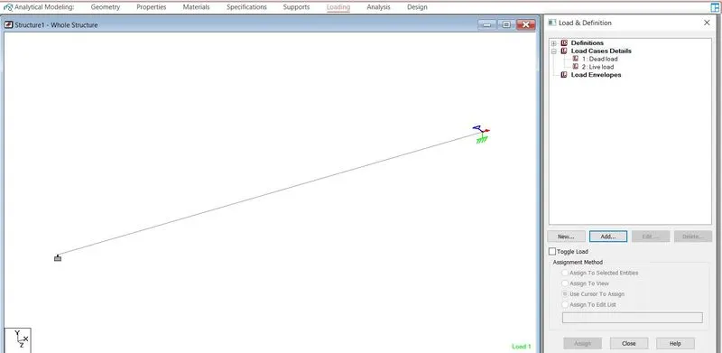
- Add load details for each dead load and live load
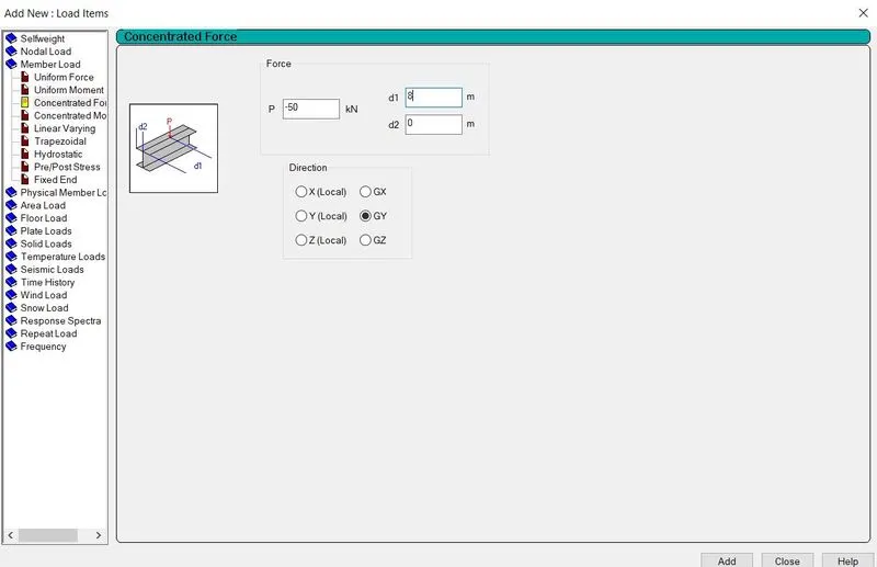
- Assign the live and dead load for the selected beam
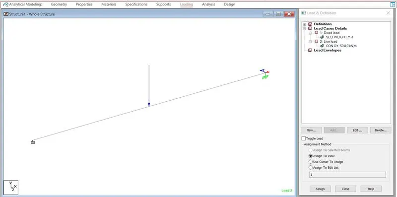
- Run the analysis and go to post processing mode
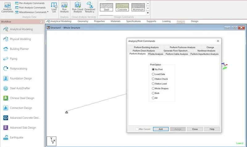
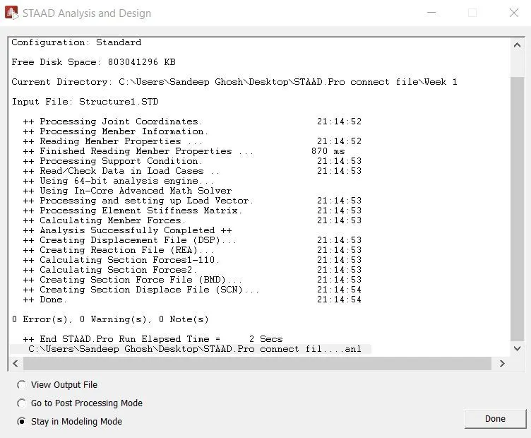
- Go to post processing mode and check its label
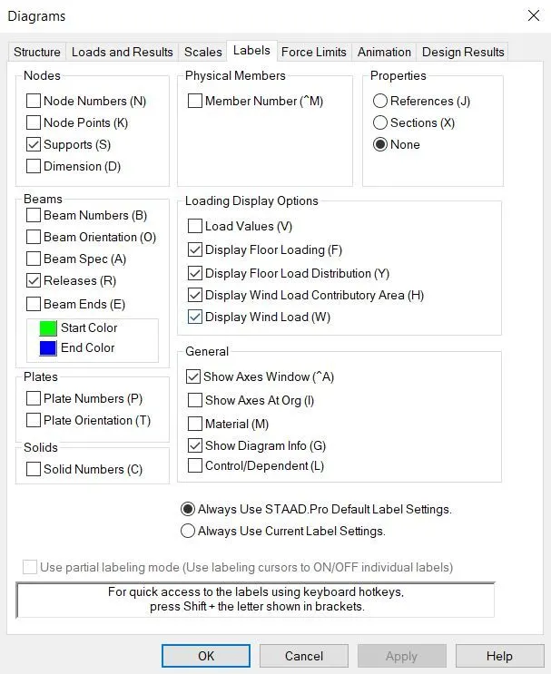
- Increase its scale to view its results
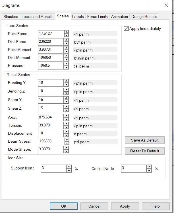
- Results are been noted down for BMD and SFD are shown below
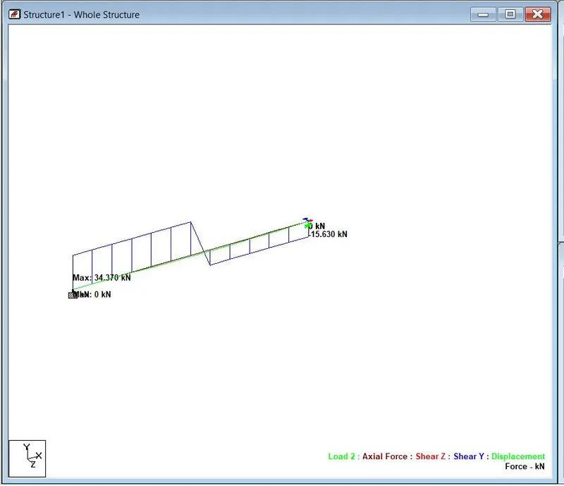
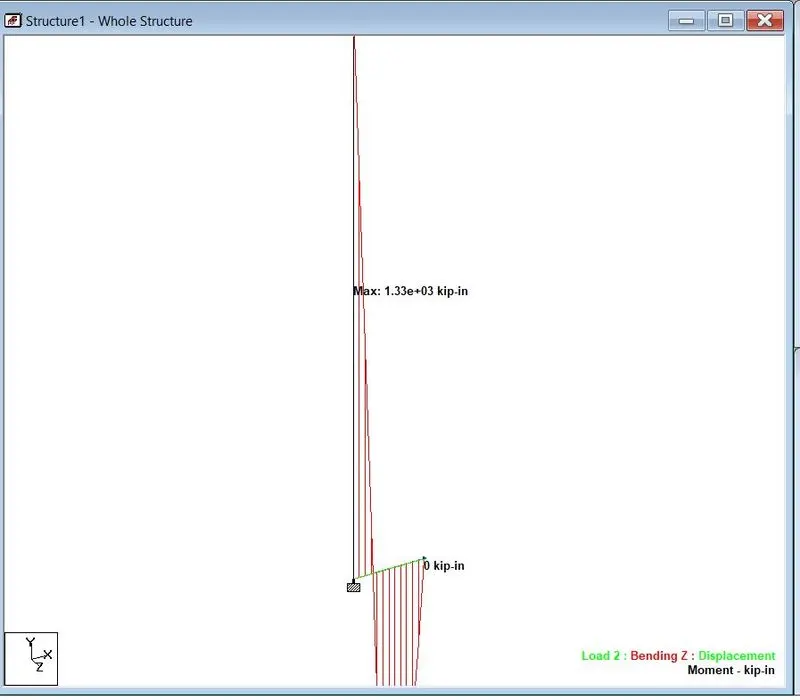
RESULTS: STAAD model has been created and the SFD and BMD diagram have been noted down it carefully