Project 1 _Creating an Architectural plan for the provided plot size and develop relevant basic structural drawings
Q. Design and Draft a layout of a residential building with the following details:
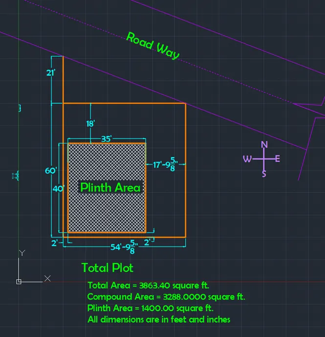
- Plot Size: 55’x60’
- Orientation- Facing North
- Develop the following: 1. Architectural Drawing (Floor Plan, Elevations, and Sections) 2. Structural Drawing (Column, Bean, Footing Plan)
Aim: To draw residential building of dimensions 55’X60’ with following drawings
- Plot drawing
- Ground Floor Plan
- First Floor Plan
- Elevation
- Center line drawing
- Footing Layout
- Beam Layout
- Section View
Introduction:
The residential building to be drawn with plot dimensions 55’X60’. The plinth dimensions are chosen as 35’X40’. The G+1 floor is designed as duplex house with stairs inside the house. The plot is north facing. The building is designed with following rooms
- Ground Floor Living Room
- Kitchen (Open)
- Main Bedroom
- Puja Room
- Staircase to first floor
- First Floor Living room
- Bedroom-2
- Guest Bedroom
- Balcony
- Staircase to roof
Building is designed with main door at the North-East (Ishan) facing north and main gate at north west position. Initially layers are created for all the components of the house.
The dimensions of the components of house are as follows
Walls
- Thickness of main walls is taken as 9”
- Internal wall thickness is taken as 4.5”
Columns and Beams
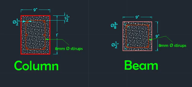
- All the columns are of size 9”X12” or 12”X9” respectively
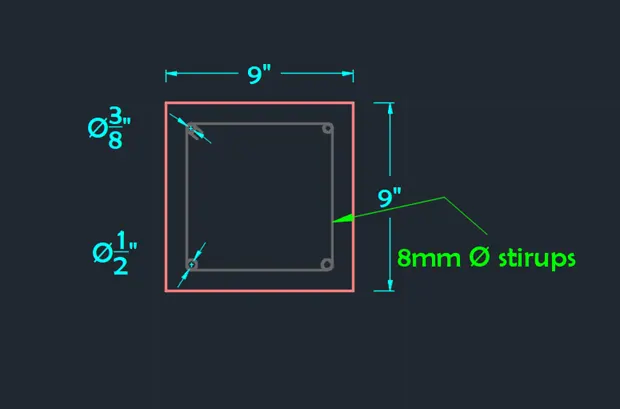
- All the beams are of size 9”X9”
- Rebar specifications are explained in procedure
Doors
There are three door types
- Dimension of Main door and entrance 4’X8’ and at the balcony access
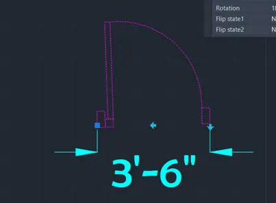
- Dimension of doors of all bedrooms are 3’6”X7’
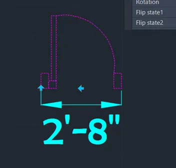
- Dimension of doors of all toilets and Puja room are 2’8”X7’
Windows
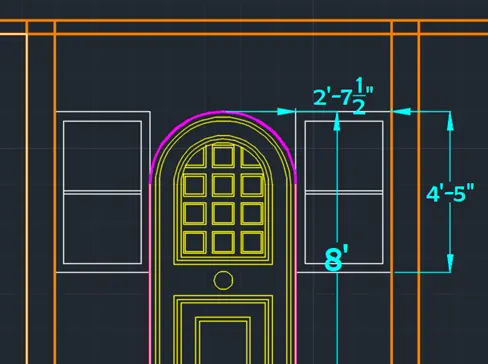
- Windows to the side of main door are taken as 2’7.5”X4’5”
- Windows in main bedrooms and in both halls 3’X5’6”
- Windows over the bed lights as 1’6”X4’6” in all bedrooms
- Ventilators as 1’6”XN depending on its preferred height
Staircase
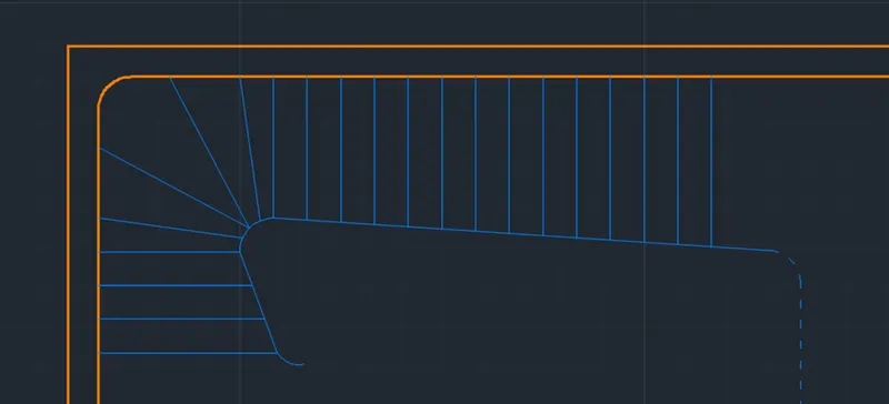
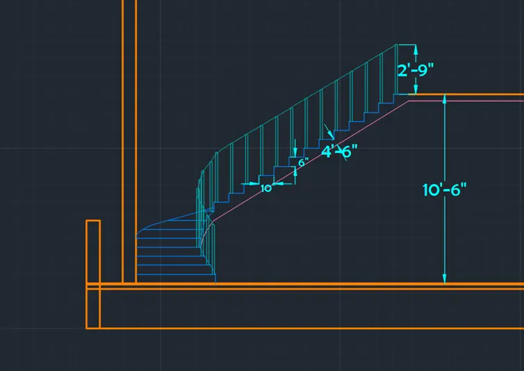
- Inner Staircase consist of 21 steps with curved steps at the change in flight direction making it single flight straircase
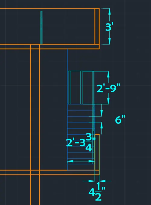
- Thread and Raiser are taken as 10” and 6” respectively
- Curve radius is also taken as 10”
- Outer staircase is connected to the roof with 21 steps
- Thread and Raiser are taken as 10” and 6” respectively
- Hand rails are 2” in diameter and height of 2’9”
Compound wall
- Height of compound wall is taken as 6’
- Thickness of compound wall is similar to wall thickness i.e. 9”
Procedure:
Open AutoCAD
In Start-up settings start from scratch select Imperial (Feet and Inches)
Open grid and snap settings
- Change snap and grid spacing to 1’
- Change major line every grid line to 10
- Turnoff adaptive grid
Type ‘un’ in command box and press enter
Change units’ type to decimal and precision to 1’1/16” and insertion scale to inches
Step 1: Creating Layers
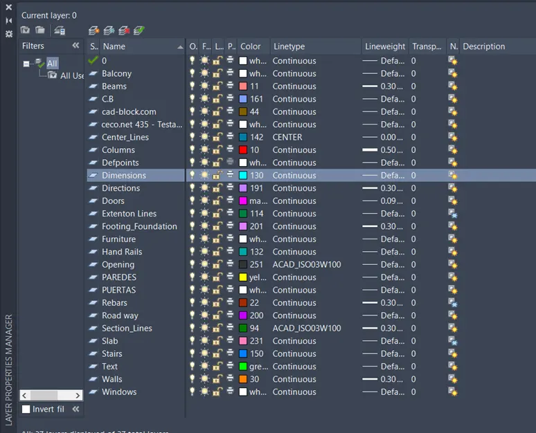
Open Layer properties and create new layers by clicking on new layer or right click on any layer and select new layer to create new layer
Layers are created as follows
Step 2: Creating Plot Drawing
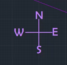
Initially direction mark is made drawing perpendicular lines and adding text and respective layer is assigned
Change the current layer to wall layer
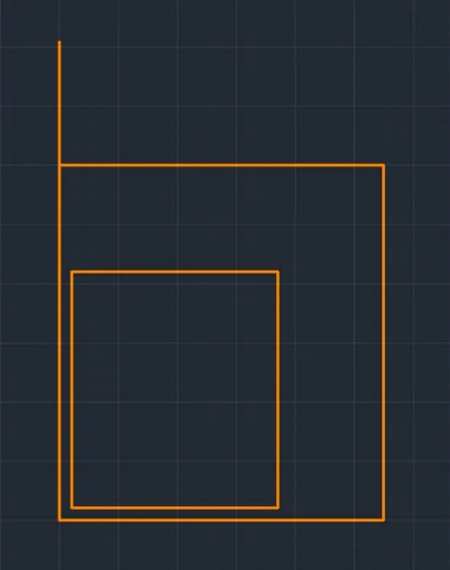
- Draw a rectangle of dimensions 60’X54’9.625” at any point on the screen
- Draw a line vertically up from top left corner of distance 21’
- Offset the left and bottom line of rectangle drawn to distance of 2’ right and up respectively
- Offset the top line of rectangle drawn to distance of 18’ to downwards
- Offset the right edge line of rectangle drawn to distance of 18’ to downwards
- Trim off the extra portions of inner rectangle
-
- Draw the roadway of width 15’ along with center alignment line
- Add relative text to the plot drawing
- Hatch the plinth area using hatch type ANS137 and hatch scale 100
-
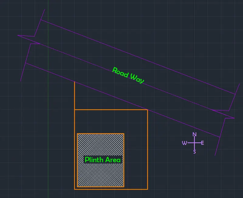
Result with text and dimension is provided in the result
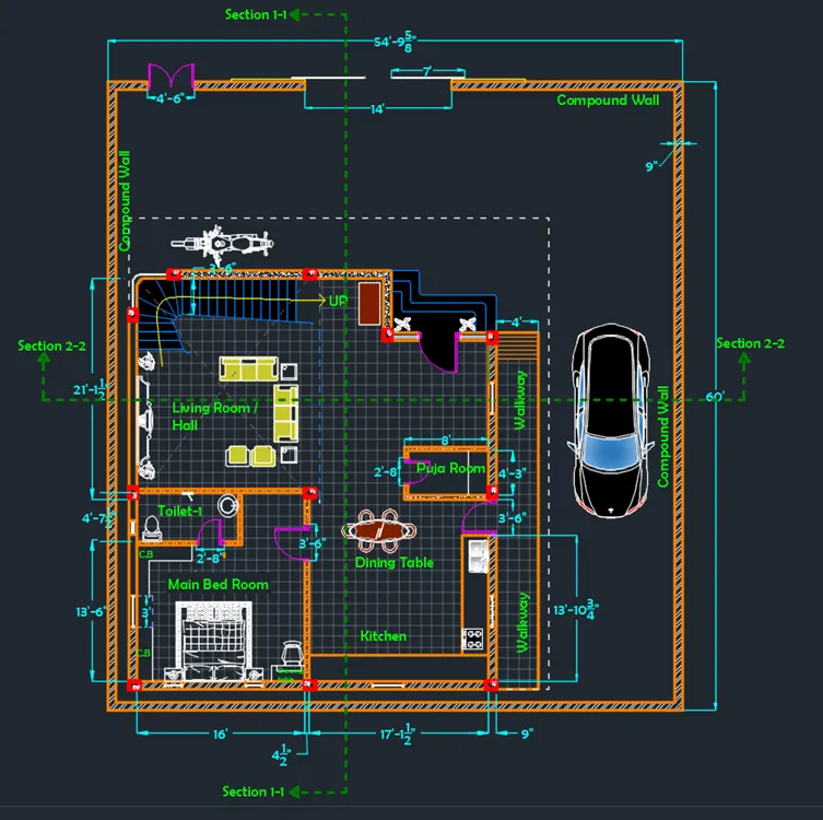
Step 3: Creating Ground Floor Plan View
A. Creating Walls
Change the current layer to walls layer
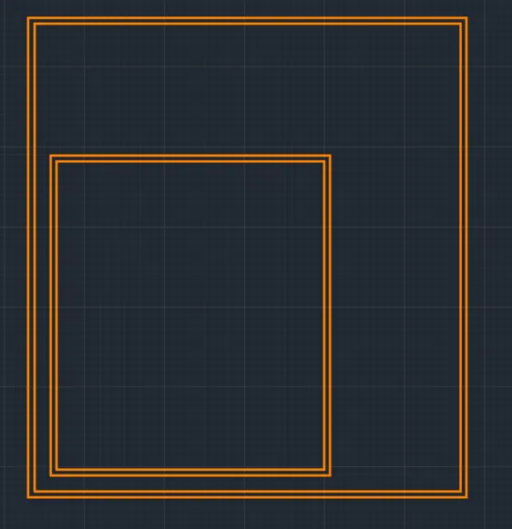
- Draw a rectangle of dimensions 60’X54’9.625” at any point on the screen
- Offset the left and bottom line of rectangle drawn to distance of 2’ right and up respectively
- Offset the top line of rectangle drawn to distance of 18’ to downwards
- Offset the right edge line of rectangle drawn to distance of 18’ to downwards
- Trim off the extra portions of inner rectangle
- Offset both rectangle to a distance of 9” to inside to give the wall thickness
- Draw the inner walls of thickness 4.5”
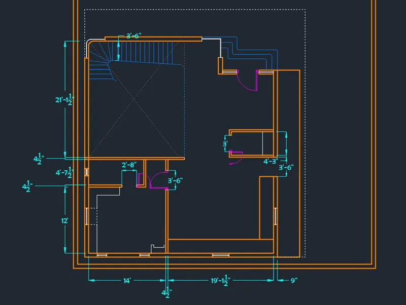
- Offset the bottom inner wall edge to a distance of 12’
- Offset the last offset line to a distance of 4.5”
- Offset the last offset line to a distance of 4’7.5”
- Offset the last offset line to a distance of 4.5”
- Offset the left inner wall edge to a distance of 14’
- Offset the last offset line to a distance of 4.5”
- Offset the last offset line to a distance of 4.5”
- Offset the last offset line to a distance of 4’3”
- Offset the last offset line to a distance of 4.5”
- Trim off the extra lines to obtain the figure as shown below
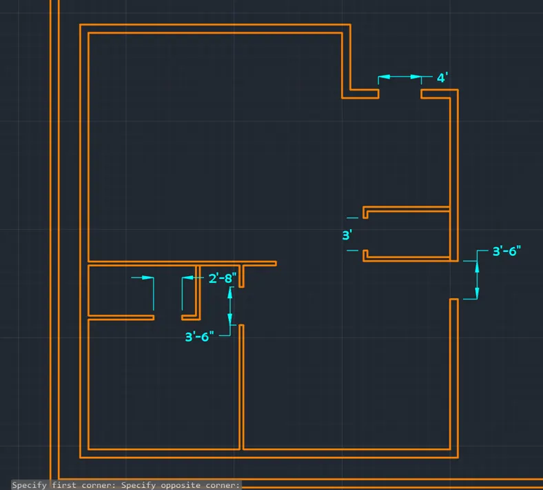
Create the front door inside the top right corner as shown in below figure
Create the main door opening of the dimension 4’
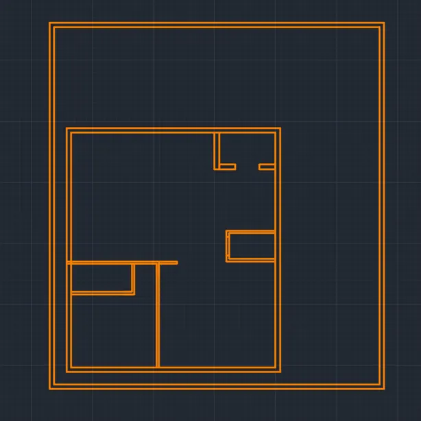
Create the door openings of the puja room, main bedroom and toilet in main bedroom as shown in the figure
Trim off the extra portions at the main door
B. Creating Stairway
Change the current layer to stairs
- Draw a thread of stair line of width 3’6”
- Offset the line to distance of 10” to upwards
- Change the direction of stairs after 5 threads of stairs
- Draw another 16 threads lines of width 10” as shown in figure
-
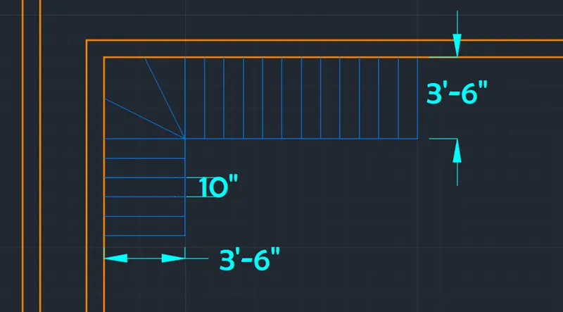
Change the step shape as shown in figure for an aesthetic look
3 Number of stairs are drawn at the main door as shown in the figure
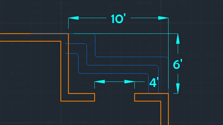
C. Creating Doors and windows
Doors and windows are created as blocks and then added to the drawing
Doors
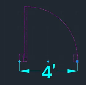
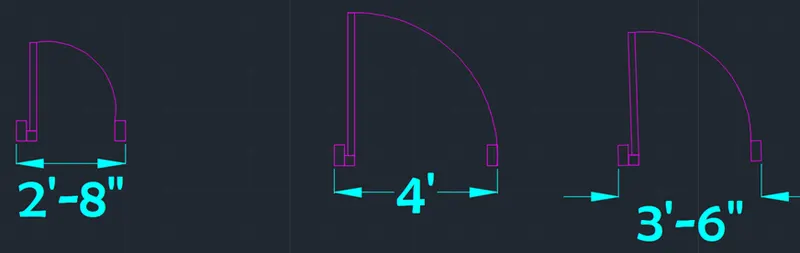
Create all door 1 using rectangles and arc of required width as shown in following figures
Convert the drawing into block using block command with name “Main_Door_4’ ”
Open the block editor and add flip states by adding parameters and actions as shown in the figure
D1: 4’-wide(Main Door)
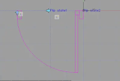
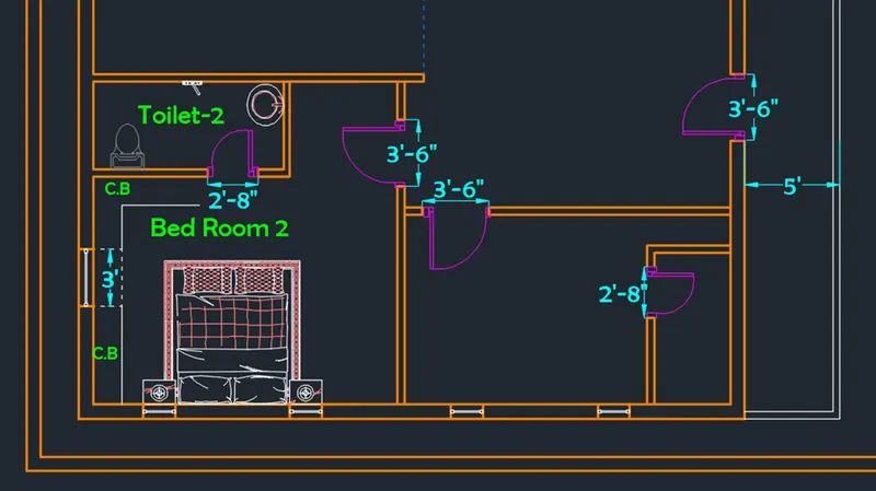
D2: 3’6”-wide (Bedroom Door)
D3: 2’8”-wide (Small Door)
Windows and Ventilators
Windows are created by using rectangles and offset lines from center
Top and bottom lines are draw using wall layer and rest in window layer as shown in figure
Block is created using block command
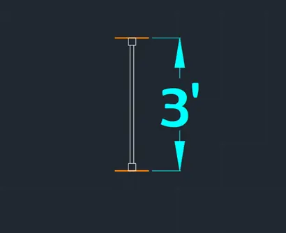
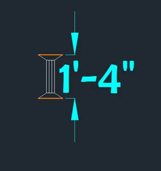

Add windows at the stairway and both side of the main door each of 2’7” and top right wall edge corner
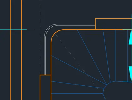
After adding doors and windows, stairway the drawing is as follows
D. Adding Furniture and Plumbing Equipment
Design center command is used add home furniture, kitchen equipment, and plumbing equipment for the rooms
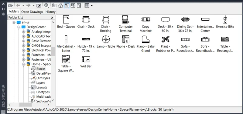
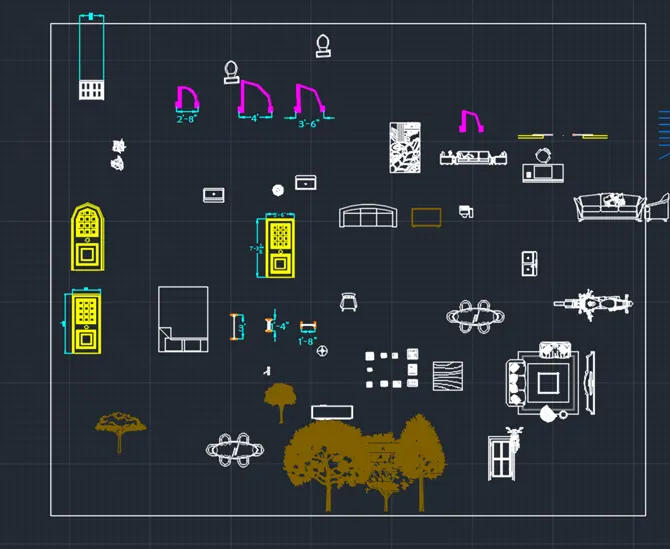
Some addition furniture is imported from another file from the internet called ‘mubles’
Furniture added from both is
- Dining Table
- Chair-Rocking
- Plant
- Bed-Queen
- Toilet-Top
- Kitchen-Hob
- Kitchen-Sink
- Entertainment set
- Sofa for living room
- Plumbing Equipment
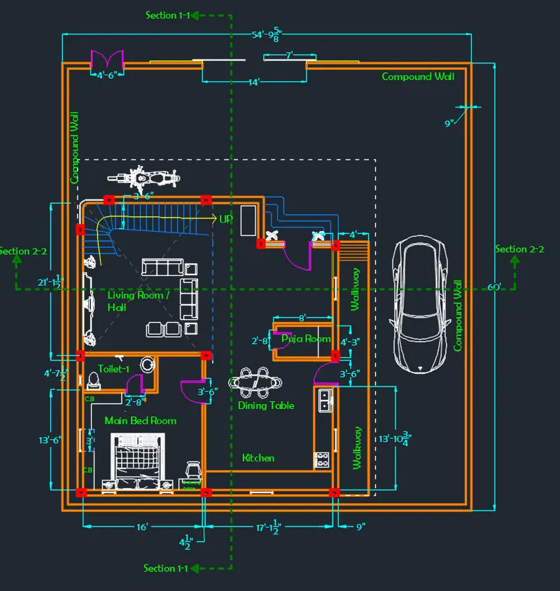
E.Result of Ground Floor Plan
At the end draw a walkway to the right of the plot as shown in figure
After giving dimensions and text the plan of ground floor is as follows
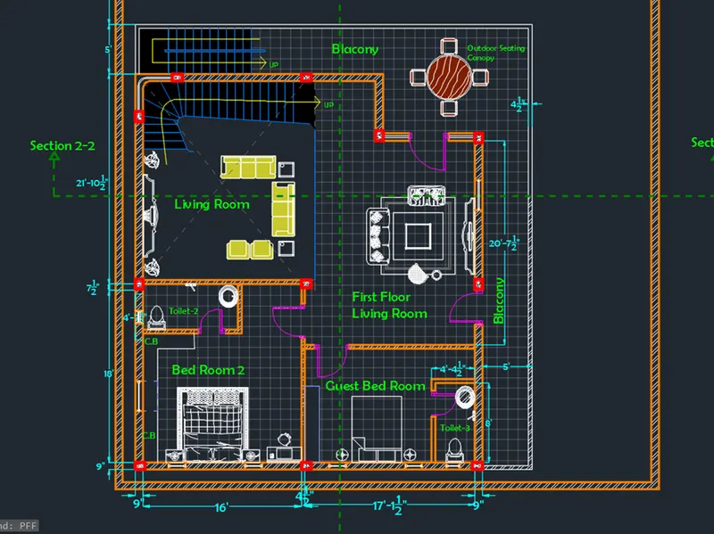
Step 4: Creating First Floor Plan View
A. Creating Walls
Change the current layer to walls layer
- Draw a rectangle of dimensions 60’X54’9.625” at any point on the screen
- Offset the left and bottom line of rectangle drawn to distance of 2’ right and up respectively
- Offset the top line of rectangle drawn to distance of 18’ to downwards
- Offset the right edge line of rectangle drawn to distance of 18’ to downwards
- Trim off the extra portions of inner rectangle
- Offset both rectangle to a distance of 9” to inside to give the wall thickness
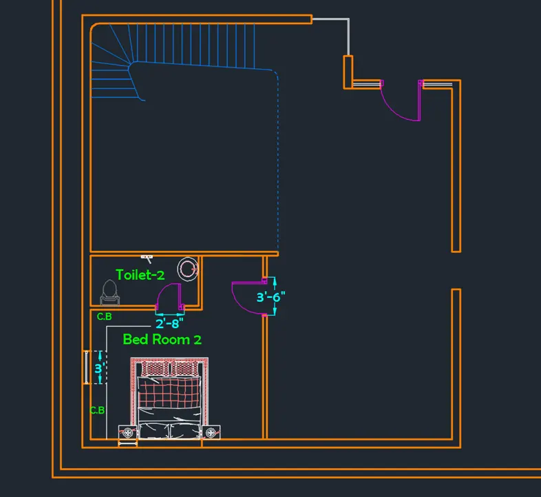
As most of the plan is same for the first floor as well, such as
- Dimensions of the main bedroom and bedroom 2 are same
- Dimensions of stairway
- Doorway to the balcony is similar to it draw in ground floor plan
So all the necessary things are select and copy pasted into the first floor drawing as below
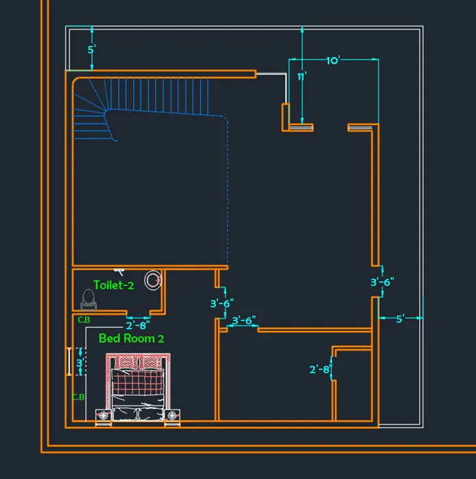
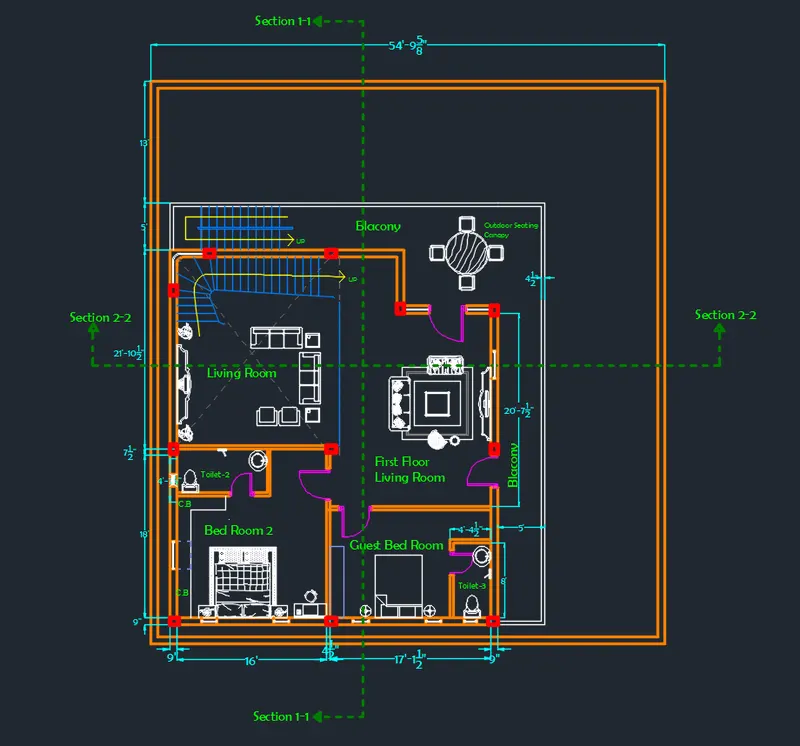
B. Balcony
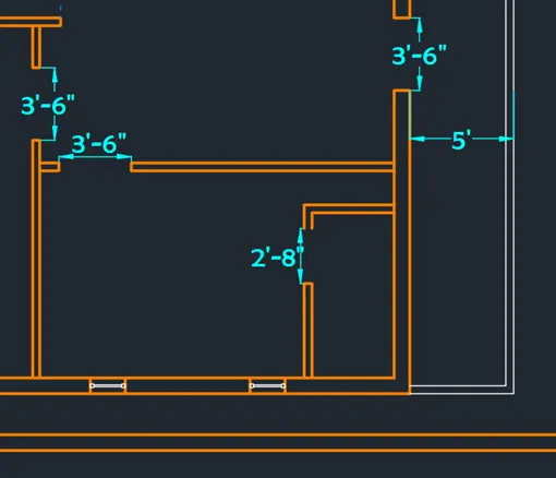
Using line command Balcony of width 5’ along top and right sides is drawn as shown in figure
Balcony wall of height 4’ is drawn with thickness as internal wall thickness of 4.5”
Guest bedroom with in room toilet is drawn as shown in the figure
C. Stairway, Doors and windows
Inner Stairway, doors and windows are created as per Step 3-(B&C) as mentioned above
Outer Stairway
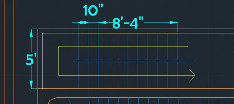
Stairway for roof is built at the Northwest
Change the current layer to stairway
- Draw stairs along the width of balcony with ½ the width as width of step
- Dimension of thread is 10”
- Total number of stairs is 21
D. Adding Furniture and Plumbing Equipment
Furniture is added
Some addition furniture is imported from another file from the internet called ‘muebles’
Furniture added from both is
- Bed-Queen for both rooms
- Toilet-Top
- Sink in Toilet
- Entertainment set for first floor Living room
- Computer Table and Chair
- Outdoor seating Canopy
- Plumbing Equipment
E. Result of First Floor Plan
At the end draw a walkway to the right of the plot as shown in figure
After giving dimensions and text the plan of ground floor is as follows
Step 5: Creating Front and Side Elevations
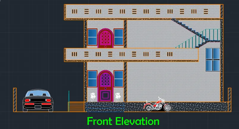
A. Front Elevation
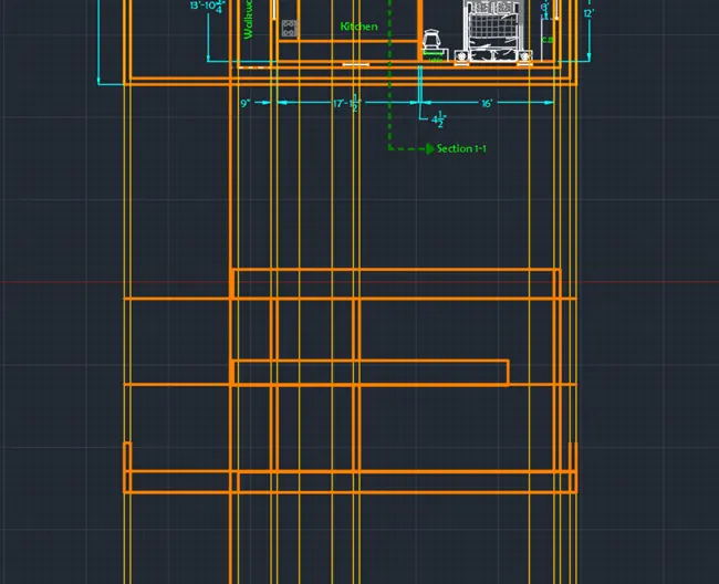
For obtaining the proper front elevation view from the north, vertical mirror view copy of the ground floor is created
- Change the current layer to extension lines
- Create vertical extension line at all the wall edge points
- Draw all the wall with their thick
- Each floor height is taken as 10’6”
- Trim the extra portions
a. Doors and Windows
- Doors and windows for elevation are similar to those added in section 2-2 view
- Door of first is half visible because of the parapet wall as shown in figure
- Curved Window along the inner staircase is added at a height of 7’ from the roof bottom as shown in figure
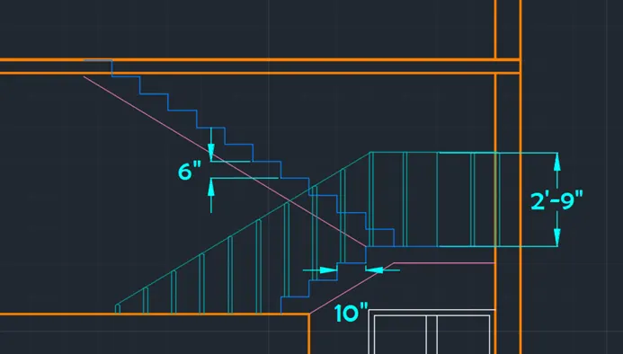
b. First Floor Staircase
- Staircase to the roof of the house is through the balcony in the first floor
- Front Elevation of the staircase is side view of the stairs
- Each step is 6” in height and 10” in length
- First six steps are invisible because of parapet balcony wall.
- After 11 steps flight changes direction
- Landing is of 3’ width
- Hand rails of height 2’9” is added to each step
- 3 Steps are drawn at the main door
c.Architectural Components
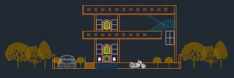
- Plants are added at the entrance on both side of main door
- Car and Bike components are added
- Trees are added as other components
- Elevation Features are added on balcony walls
d. Elevation Result
After adding all the architectural features the result of elevation without hatch is shown below
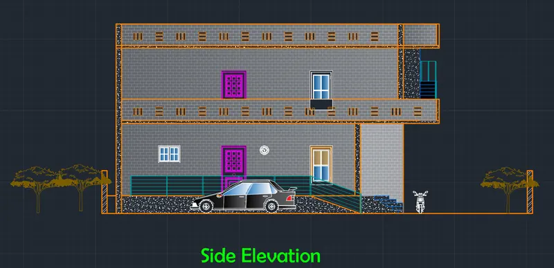
B. East Side View
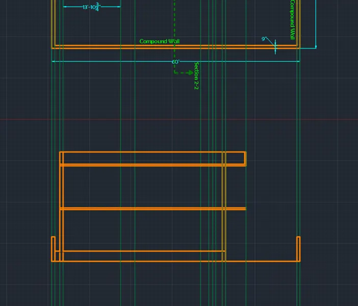
a. Walls
Rotate the drawing to 270o
- Using ‘XLINE’ command draw the extension lines at the all the intersecting points of section line and walls
- Draw compound wall of height 6’ and walls with floor height of 10’6” of the section view as shown in figure
- Parapet wall of height 3’ is draw at the top as shown in figure
- Add other wall extensions
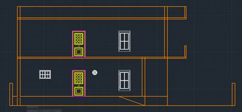
b. Doors and Windows
- Draw the projection lines of doors and windows
- Door is of dimension 3’6”X7’
- Draw the windows using offset of series of rectangles
- Import the ventilator from blocks
- Draw a smaller kitchen window above the kitchen hob.
c. Staircase and Side Ramp
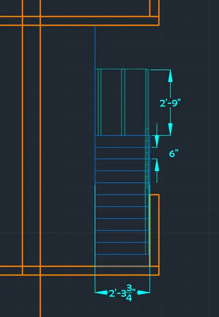
- Staircase to the roof is located at the front balcony which from side is a front view
- Outer stair case is drawn with each step height 6”
- Handrails along the edge as shown in figure
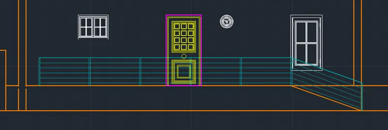
- Side ramp is right-side of the main door
- Hand rails are drawn along the side ramp
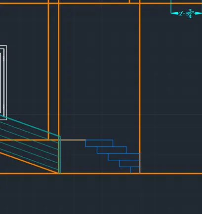
- Staircase at front door is drawn as below
- Consist of 5 steps
Elevation features are added
Slab thickness is 5” i.e., 125mm
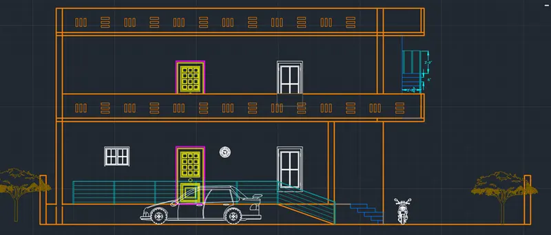
d. Result
The final result of side view without hatching is shown below
Step 6: Creating Section Views 1 and 2
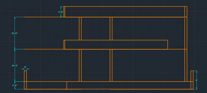
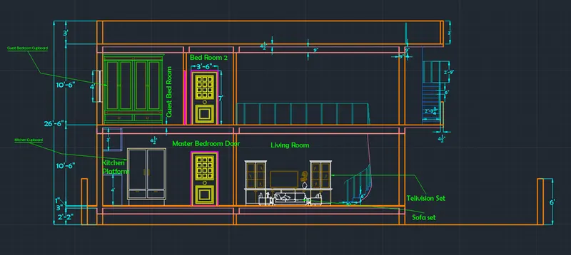
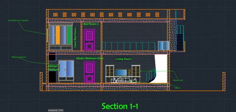
- Section View 1-1
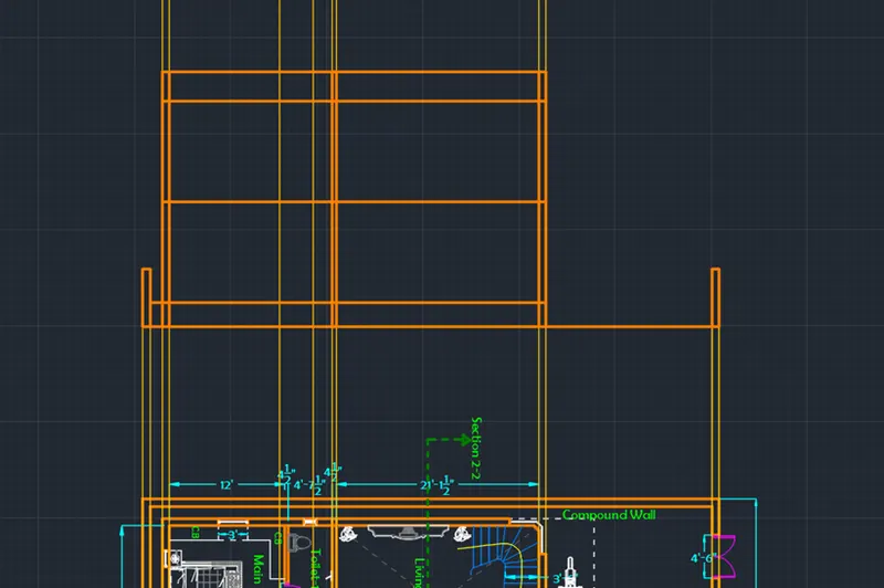
a. Walls
Rotate the drawing to 270o
- Using ‘XLINE’ command draw the extension lines at the all the intersecting points of section line and walls
- Draw compound wall of height 6’ and walls with floor height of 10’6” of the section view as shown in figure
- Parapet wall of height 3’ is draw at the top as shown in figure
b. Staircase
- After drawing walls from the projection lines, delete those projection line
- Now draw the projection lines for the stairs
Change the layer to stair layer and draw the stairs
- Draw the 5 steps from the side view along with side rails
- Draw the slab below stairs using slab layer as shown in figure
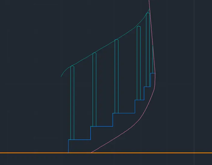
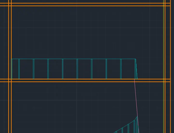
Draw the hand rails in the first floor along the duplex opening as shown in figure
Outer stair case is also drawn with each step height 6”
Handrails along the edge as shown in figure
c. Doors
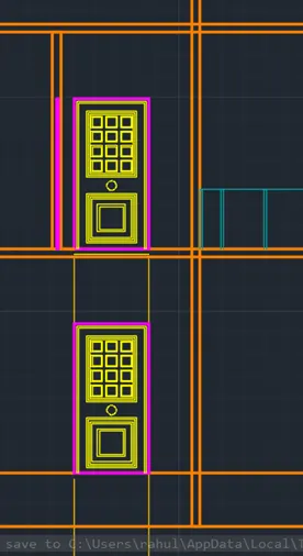
- Doors of main bedroom and bedroom-2 are drawn using door layer and from the projection lines
- Dimensions of both doors is 3’6”X7’
- Doors pattern is imported from the challenge 8
- Doors are added as shown in figure
d. Windows and Cupboards
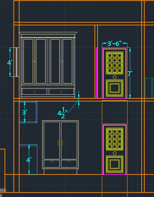
- Window for the guest bedroom is drawn with dimensions 1’6”X 4’
- Cup boards for the kitchen room and the guest bedroom are drawn using C.B layer created
- Kitchen Platform of height 4’ is drawn along with top cupboard
e. Living Room
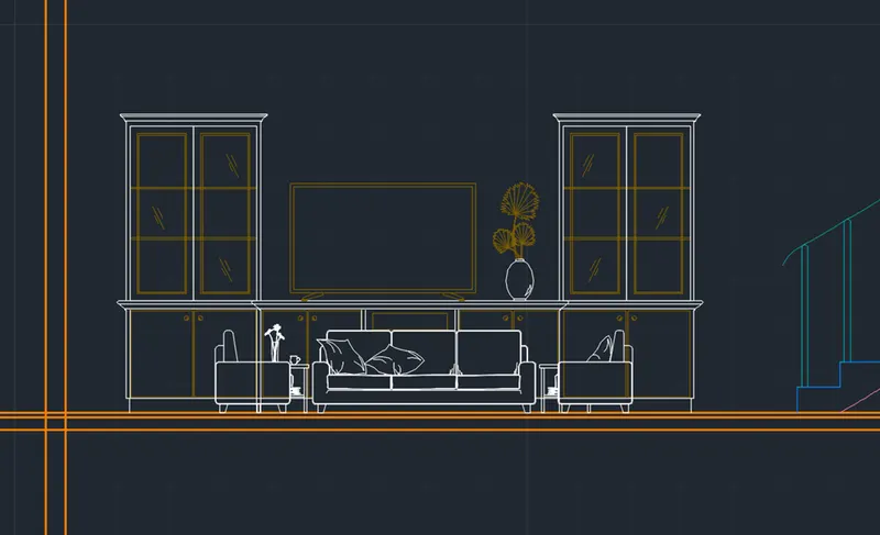
Sofa Blocks and Television set are added to the section by importing the AutoCAD blocks from internet as shown n figure
f. Beams and Slabs
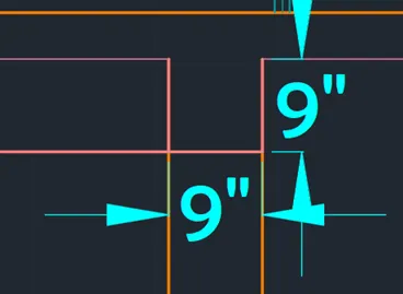
Slab Thickness is given as 4.5”
Beams of dimensions 9”X9” are placed where ever required
The final Result of the section 1 view without hatching is shown below
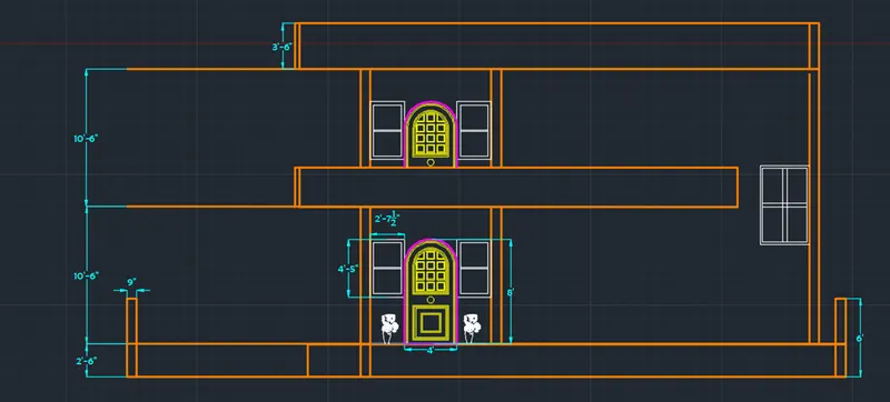
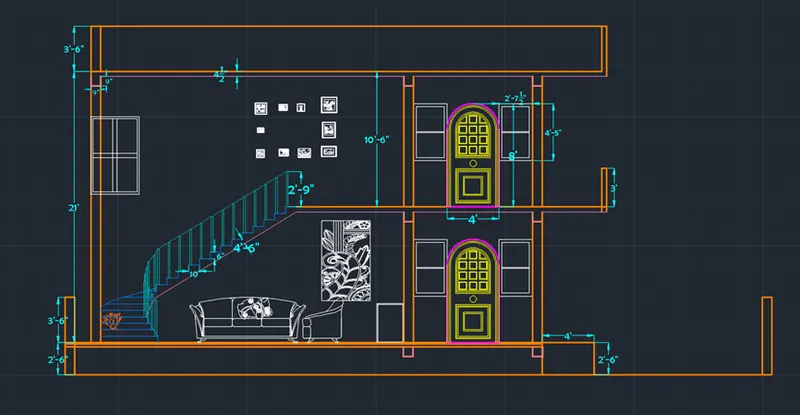
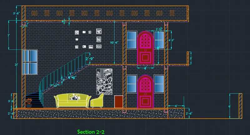
2. Section View 2-2
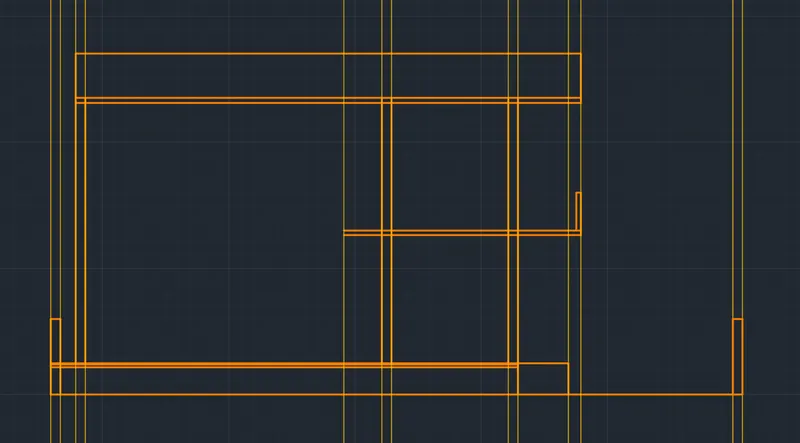
a. Walls
- Using ‘XLINE’ command draw the extension lines at the all the intersecting points of section line and walls
- Draw compound wall of height 6’ and walls with floor height of 10’6” of the section view as shown in figure
- Parapet wall of height 3’ is draw at the top as shown in figure
-
b. Staircase
- After drawing walls from the projection lines, delete those projection line
- Now draw the projection lines for the stairs
Change the layer to stair layer and draw the stairs
- Draw the 5 steps from the front view along with side rails
- Draw the slab below stairs using slab layer as shown in figure
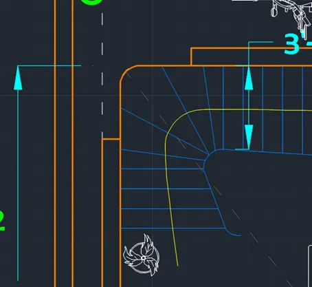
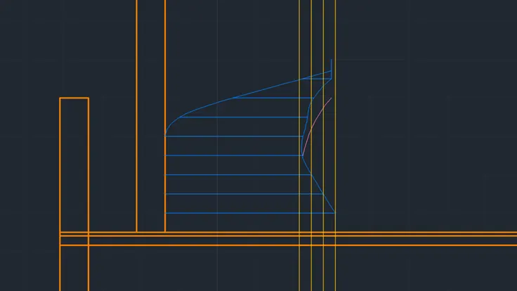
1Plan View 2Section View
- After drawing remaining steps and hand rails the final view of steps is shown below
c. Doors
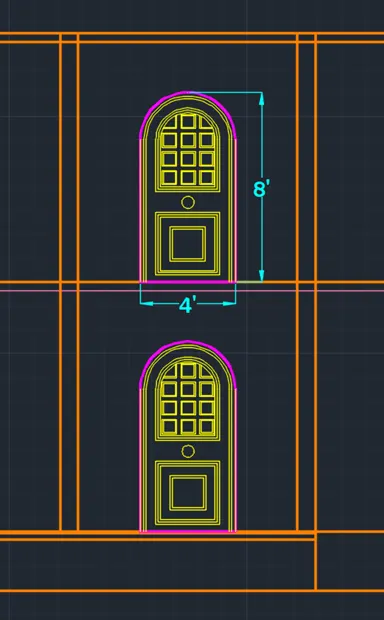
- Main entrance door and balcony door are drawn using door layer and from the projection lines
- Dimensions of both doors is 4’X8’
- Doors pattern is imported from the challenge 8
- Doors are added as shown in figure
d. Windows
- Windows at both sides of the door are created with dimensions 2’7.5”X4’5”
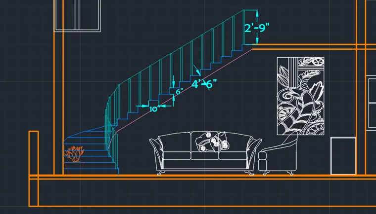
f. Sofa and other furniture
- Section view ground floor living room sofa is added
- Plant beside the Television set is placed
- Shoe stand is placed beside the projected wall as shown in figure
- Art Work portrait block is added in the living room
g. Beams and Slab
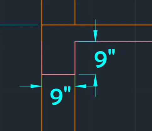
Slab Thickness is given as 4.5”
Beams of dimensions 9”X9” are placed where ever required
The final Result of the section 1 view without hatching is shown below
Step 7: Creating Other Drawing layouts
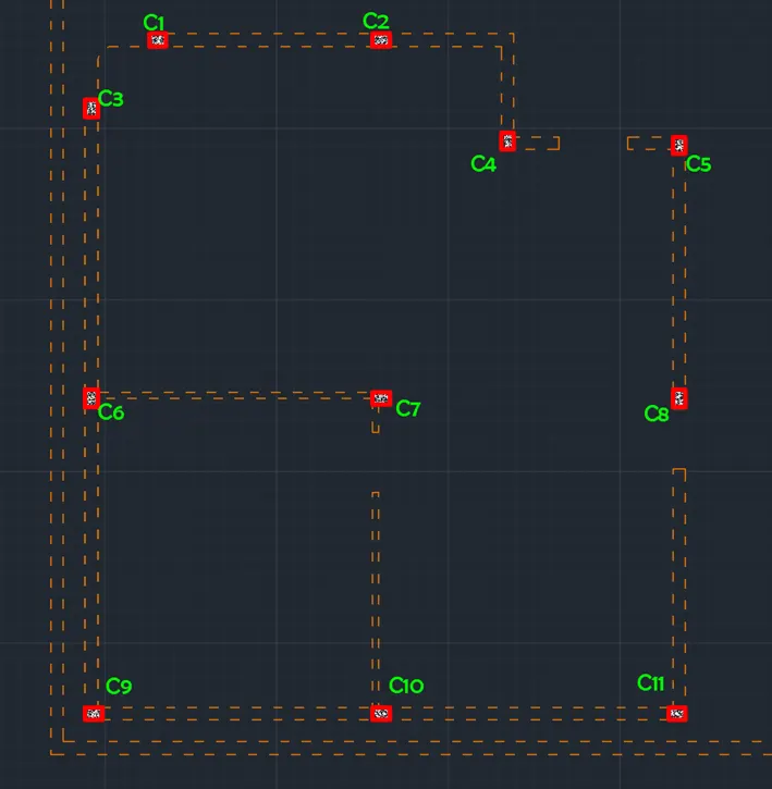
- Column Layout
Change the current layer to wall layer
- Draw all the walls of the plan view excluding doors and windows
Change the current layer to column layer
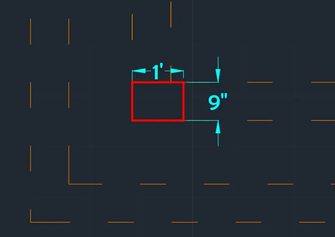
- At the bottom left corner draw a rectangle using column layer
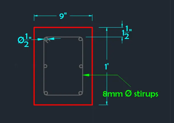
- All the columns are of size 9”X12” or 12”X9”
- Columns are placed along the direction of wall in some cases
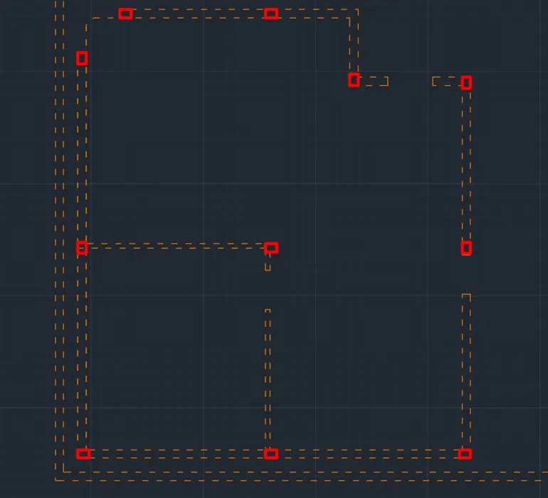
- Draw the columns at all necessary points
The column layout for the G+1 residential house is as follows
- Reinforcement in column consists of 6 bars of 0.472” diameter(12mm) bars
- Stirrups of side 0.315” i.e.8mm dia bars with 150mm center to center spacing
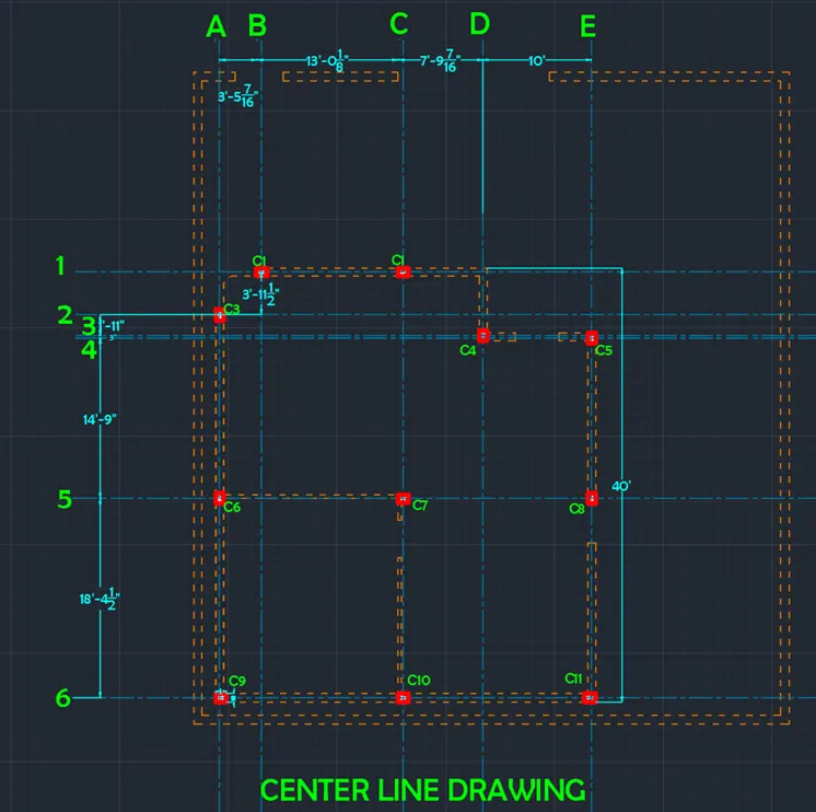
II. Center Line Drawing
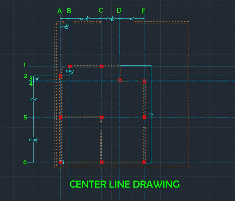
Change the current layer to center line
- Draw the lines connecting centres of all columns in line
- Both horizontal and vertical center lines are drawn
- Give codes with alphabets for vertical center lines
- Give code with number for horizontal center lines
- The distance from one center line to another is to be shown
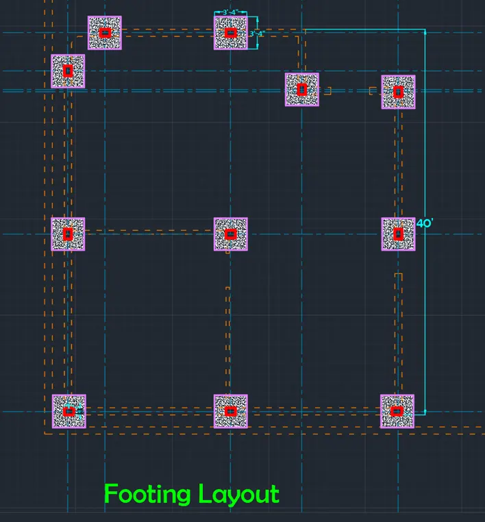
III. Footing Layout
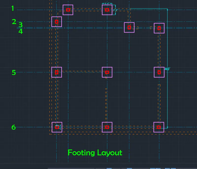
- Draw the column layout again
- Change the current layer to ‘Footing_Foundation’
- Draw a rectangular footing circumscribed in a circle of radius 1’8”
- Dimension of all footings drawn is 3’4”X3’4” (1mX1m)
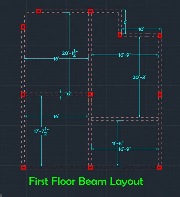
IV. Beam layouts
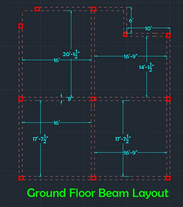
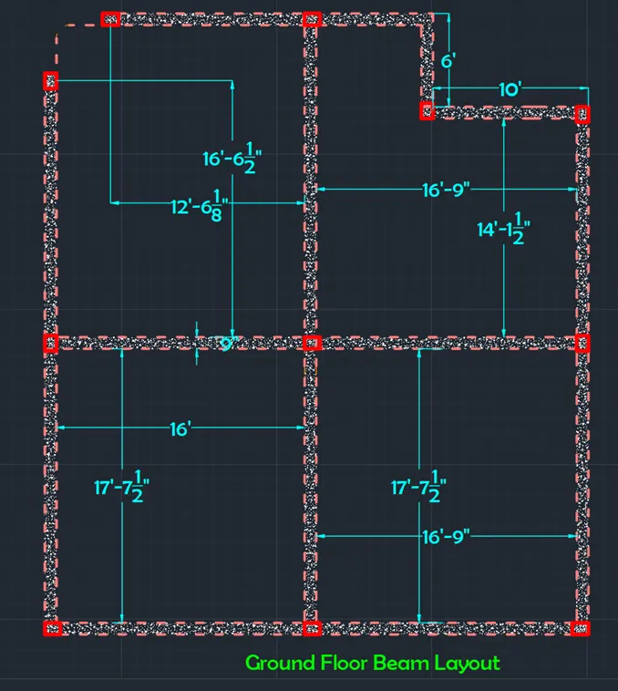
i. Ground floor Beams layout
Change the current layer to beam
- Draw the column and wall layout of the ground floor plan
- Beams are drawn with dimension 9”X12” (12” is the depth of the beam)
- Beam is not used above the bathroom and puja room walls
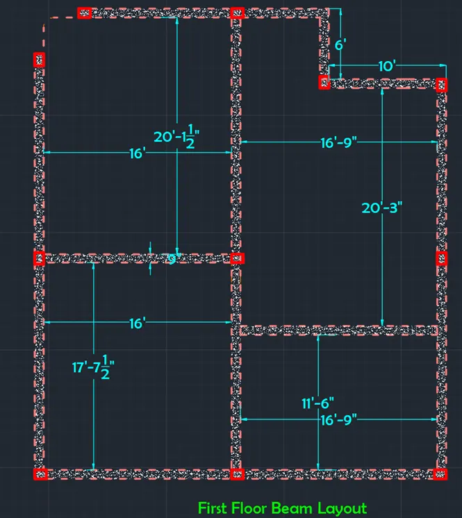
ii. First Floor Beams layout
The only change between ground floor plan and first floor plan is the beam over the guest bedroom wall as shown in figure
- In beam, 4 bars, with 2 bars of 0.472” (12mm) thickness in the bottom of the beam, and 2 bars of 0.4” (10mm) at the top of the beam
Step 8: Hatching
The hatching is done for all components of plan and elevation
Elevation patterns are chosen and applied with their respective attributes
Hatch patterns used for respective props are
- All the walls in top view and side view are hatched with ANS132
- All walls in front view are hatched with BRICK pattern
- All beams and slabs are hatched with AR-CONC
- All floors are hatched with ANS137
- All Doors are hatched with solid colour patterns
- All windows are hatched with gradient blue patterns
Result:
Residential G+1 floor design consists of plot drawing, plan view, center line drawing, column and beam layouts, elevation view and section views are drawn. The house consists of 3 bedrooms, 2 living rooms, puja room, kitchen and balcony. Layers are created in the first step and assigned accordingly. After drawing plan view one horizontal section and vertical section lines are drawn named as section 1-1 and section 2-2. Required components and furniture to the house are added using design center command and some other files are added from the cad blocks from browsing. Step by step procedure for all components is shown in respective steps.
Vastu Shastra Followed
- Entrance of the house is provided at the North-East position.
- Living room is provide at the North-West position of the house.
- Master bedroom and Guest bedroom is provided in the South-West position of the house.
- Kitchen is provided at the South-East position and hob is placed such that cooling is done with facing east
- Pooja room is provided at the East.
- Bathroom placed in the west.
- Staircase provided in the North- west.
- Balcony is provided at North and East positions.
In the first 7 steps, all the drawings are drawn. At the end of each step, result of that step is shown. Using step 8 hatching is done for all the drawings. The final result consists of all the drawings of the residential house with hatching.
- All dimensions are in feet and inches
- Dimensions are assigned accordingly
- Text is assigned for all the required components
1. Plot Drawing
2. Ground Floor Plan View
3. First Floor Plan View
4. Front Elevation View
5. East Side Elevation View
6. Section 1-1 View
7. Section 2-2 View
8. Other Drawings
A. Column Layout
B. Center Line Drawing
C. Footing Layout
D. Ground Floor Beam Layout
EFirst Floor Beam Layout
9. Rebar Details