Week 1 Challenge
CHALLENGE 1
A) Step involved in upload staad file through web mail.
- STAAD PRO – Structural analysis and design program is the abbreviation it is used to analyse RCC and steel design.
- To open the staad.pro connect software using staad.pro shortcut icon on desktop.
- To click share icon on the loading page of the software.
- Click send mail and select the file you want to share, after that click send mail. All the process are under take by first login the staad pro account.
B) Type of material used in staad.pro
- Concrete
- Aluminum
- Stainless steel
- Steel
C) Capture image in staad.pro
Yes it is possible to capture image in staad pro using sketch pad, click windows +shift + s. choose the window icon appear on screen. drag the mouse to capture and click save the file to save as png file.
D) THREE TYPE OF CREATING A MODEL
- Using staad.pro physical modeler interface.
- Using traditional staad.pro analytical modelling interface.
- Using the command line option.
E)Assign a material to model
- To create model on geometry tab.
- Select properties icon on the model and add the material like steel, concrete and specify the shape, dimension and click finally add.
- After creating the material properties, click the created material and select the model and click the assign the selected material to assign option. The material can be assigned.
- Similar steps are followed for assign the load in the model.
- A) six parameter in RCC design for STAAD PRO
- Clear cover
- Fy main – yield strength of main reinforcement of steel
- Fy secondary – yield strength for secondary reinforcement of steel
- Fc - compressive strength of concrete
- Width of cross section used for beam design.
- Max main – maximum diameter of bar for main reinforcement.
- Max secondary – maximum diameter of bar for secondary reinforcement.
B) TYPE OF CURSOR USED IN STAAD PRO
- Node cursor
- Beam cursor
- Plate cursor
- Solid cursor
- Geometry cursor
- Members cursor
- Plates and solid cursor.
c) Generate different view for model
- The view window contains a unique control device called the Rotation gizmo which allows you to select set view orientations or to orient the model in the view about the global axes.
- Click the rotation Gizmo to display pre-set views. Click the invert icon to display the reverse of these views.
- Click and drag on the rotation gizmo axes to rotate the view about that global axis.
- Click on the zoom control to zoom in or out of part of the model.
- Click perspective control to display the perspective switch and slider.
D) Define a simply support condition in staad.pro
- Click the support icon on tool palette.
- Click on create support command.
- It show options like fixed support, pin support, fixed but, enforced but support, cable support, inclined support.
- Choose the inclined support and click add to define the support to the model.
E) Five topics in Design basics report
- Length
- Purpose of the project
- Audience
- Organization
- Executive summary
- The problem
- Design specifications
- Design assessment
- References
F) Multi material design
- It is consist of different materials place one above another. That is steel deckhouse settled on a concrete shear wall.
3) A) Type of structure system in STAAD PRO
- There are 4 type of structural system in staad pro
- Space system has 3 dimensional geometry, loading can be applied in 3 dimensional and deformation occur on 3 dimensional, any type of joint can be applied.
- Plane system has 2 dimensional geometry, loading can be applied in 2 dimensional and deformation occur on 2 dimensional, any type of joint can be applied.
- Frame system has 2 dimensional geometry, loading can be applied in perpendicular to xz axis and deformation occur on perpendicular to xz axis, any type of joint can be applied.
- Truss system has 3 dimensional geometry, loading can be applied in 3 dimensional and deformation occur on 3 dimensional, pinned type of joint can be applied.
B) Coordinate system in STAAD PRO
- They are two coordinate system in staad pro.
- Namely global axis and local axis. Global axis is fixed in coordinate system. Local axis is variable. This is used for the orientation of the beam with load variable.
C) Design basis report and its uses
- DBR refers to design basis report. To take up a project from the scratch to end this is need.
- To specify the data and compile data received and analysis and design of structural element.
- It contains the assumption and specification to develop the project.
- It will help to avoid the scope and the creep that can derail the project schedule and lead to budget overness.
- It contain general column drawing and project planning.
D) Type of Analysis option in STAAD PRO
- Perform analysis
- PDelta analysis
- Perform cable analysis
- Perform direct analysis
- Generate floor spectrum
- Nonlinear analysis
- Perform imperfection analysis
- Perform buckling analysis
- Perform pushover analysis
E) Fixed and Fixed But condition
- In fixed condition the node or the end condition are fixed are restrained with the FX, FY, FZ and the moment are also restrained.
- In fixed but condition the nodes are FX and MZ are released as it is horizontal rolled support.
AIM
To create a beam model and assign property as per given detail in staad pro.
PROCEDURE
- To create new file by specify model info and project info on the staad pro connect new file tab.
- To specify the units and click create project, after enter all the detail click geometry tab and create node using nodal table method.
- After creating node, create beam using add beam option.
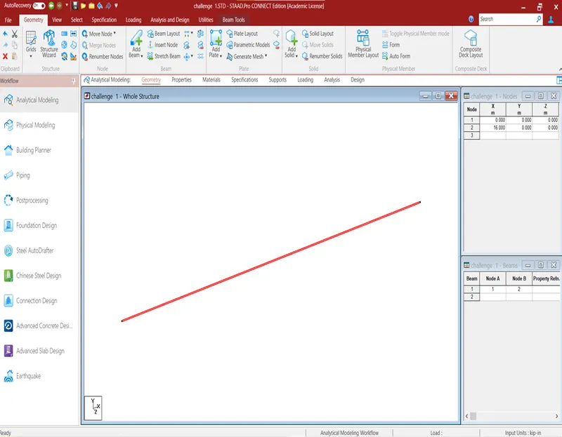
- After creating geometry, click property to assign the property for beam by using define parameter option.
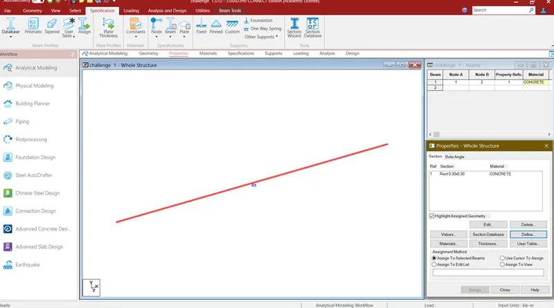
- After assigning property, click material tab to assign the material.
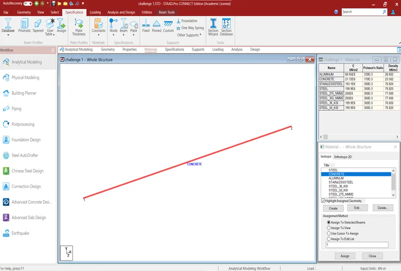
- After assign the material, click support tab to create a support. After creating the support assign the support to the beam nodes.
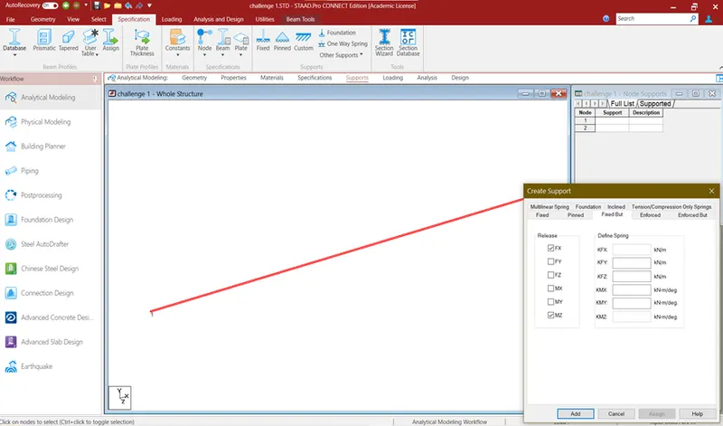
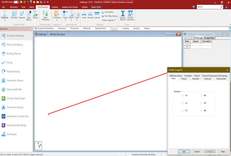
- After assign the support, click load tab and select load cases to add new load. Click new load data and click add to create type loads. After create the load on load case specify load for beam using assign the selected beam option.
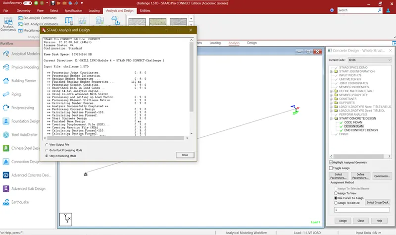
- After assign the load, click analysis tab and click create command option. Click run analysis option analysis tab system will check and run the analysis.
- After analysis done, click the post processing view to view bending moment, reaction drawing.
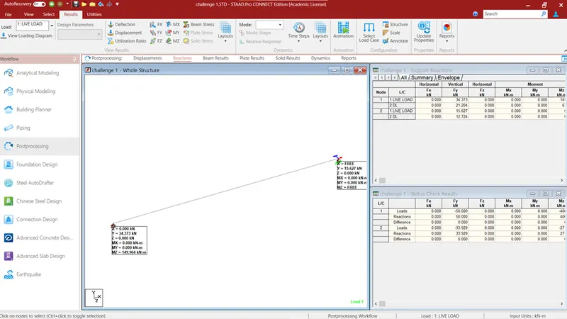
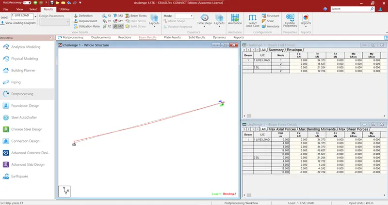
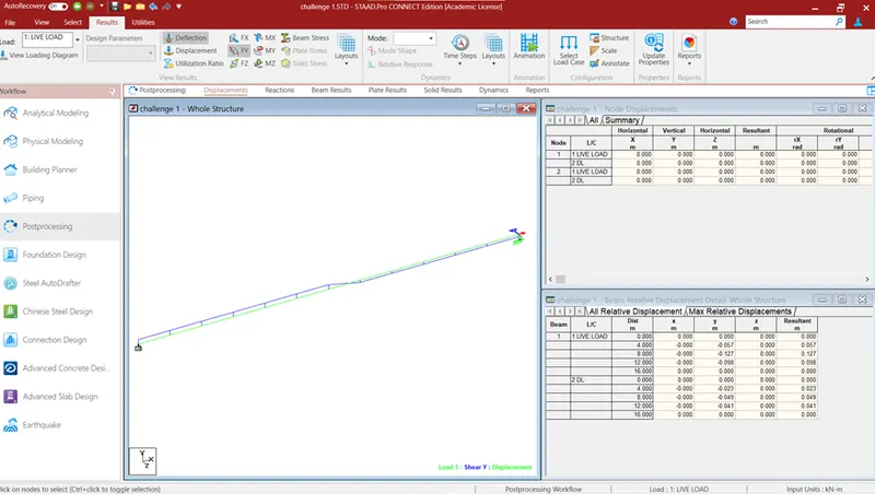
RESULT
The creation of beam model and analysis of beam as per given data has been done.