Week 1 Challenge
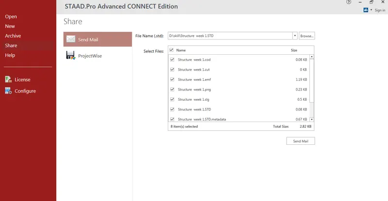
- AIM : Write the steps involved in stadd pro file through web mail
- PROCEDURE :
- Open the soaftware in the landing page
- Click on share icon
- Click on send mail
- Browse the file you want to share
- Ensure that ypu are sign in
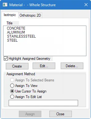
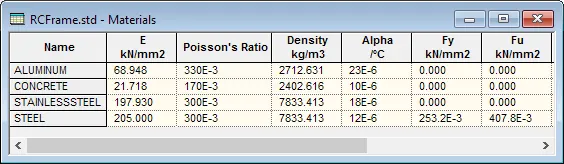
- Type of material used in staad pro
- There are three methods of creating the structure data
- Using the staad pro physical mdelar interface
- Using staad pro analytical modelling interface
- Using command line
- physical model is used to draw structural elements as they are physically constructed
- The program will then decompose this into an analytical modelling which is passed to the staad pro and analysis and design engine when you run the model
- Analystical model is finite element of the structure which is typically processed directly by the analysis and design engine
- The compound inpit file is a text file which contains the data for your structural model.This file consists of commands
e)
- In staad pro physical modeler, the general order of operation is that yopu first select physical objects and then assign properties
- This doffers from staad pro where are there many tasks in which you select the operation ,property or specification
- To navigating the model view
- The view window contains a unique control device called the rotation gizmo which allows you to sselect set view orientation or to orient the model in the view about global axes
- Check the rotation gizmo to display present views.Click the invert icon to display the reverse of these view
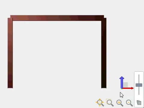
- Click add drag on the rotation gizmo axes to rotate the view about the global axes
- Click on zoom controls to zoom in or out of parts of the model click and drag the middle mouse buttonto pan the view
- CLick on perspective control to display,the perspective switch and slider to navigating the model view
- The view window contains a unique control device called the rotation gizmo which allows yoput ot select the set ciew orientaion ot to orient the model in the view about the global axes
- Click on totation gizmo to display present views.Click the invert icons to display the reverse of these views
- EXPLAIN THE PROCEDURE TO DEFINE SIMPLY SUPPORTED CONDITIONS IN STAAD PRO
- Click on create supprt command
- There we can get option like fixed support ,pin support ,fixewd but
- Enforced but support
- Cable support
- Inclined support
- NAME ANY FIVE TOPICS THAT YOU WILL INCLUDE WHILE CREATING DBR
- DBR Design basis report
- To take up a project from scratch to the end this is need
- To specify the data and compile data received and analysis and design of structural element
- It contains the assumptionand specification to devlop the project
- It will help to avoid the scope and creep that can derail the project schedule and lead to budget overness
- Contains the general column drawing
- Contains the project planning
- EXPLAIN THE COORDINATE SYSTEMS ADOPTED IN STAAD SOFTWARE
- Global axis : Global axis is fixed in the coordinate system
- Local axis : Local axis is variable
- This is used for the orientation of the beam with the load variable
- ELABORATE DBR AND ITS USES
- DBR Design basis support
- To take up a project from scratch to the end is need
- To specify the data and compile data received and analysis and design of structural element
- It contains the assumption and soecification to devlop the project
- It will help to avoid the scope and the ccreep that can derail the project schedule and lead to budget overness
- Contains the project planning
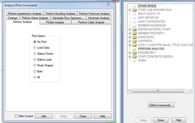
- Explain the diffrent type of analysis option in staad pro
- EXPLAIN THE DIFFRENCE BETWEEN FIXED AND FIXED CONDTION
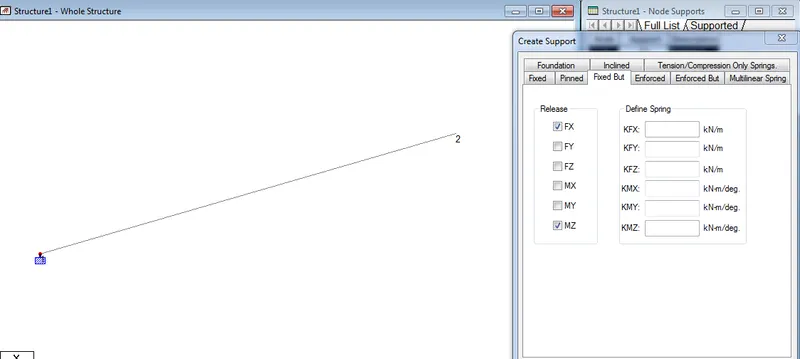
- iN FIXED CONDITION THE NODE OR THE END CONDITION ARE FIXED ARE RESTRAINED WITH FX ,FY,FZ and the moment are also restrained
- In fixed condition the node are FX and MZ are released as it is horizontal rolled support
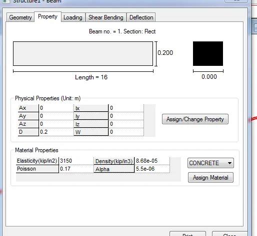
- AIM : Creating the staad model with followinf specification
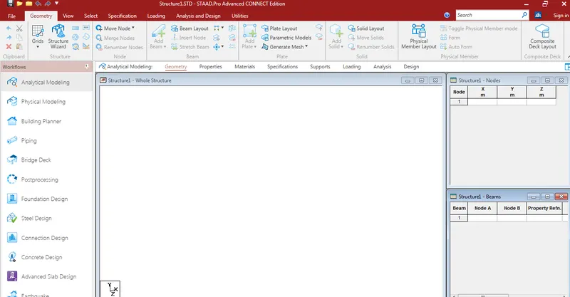
- Grid dimension are to be given spacing as 1m and in X and Y direction are 18 grid
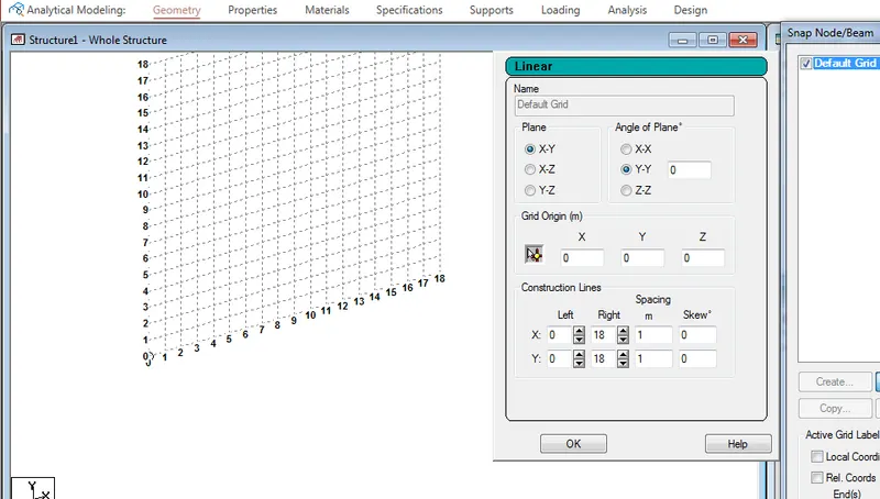
- Click on grid menu and draw a beam of span 16m
- For the node view click on CTRL + n or right click and labels and view nodes
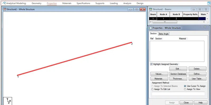
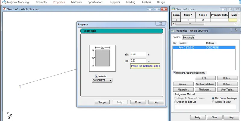
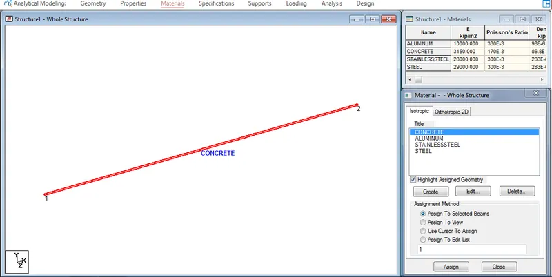
- FIXED ON ONE END AND ROLLER SUPPORT O OTHER END
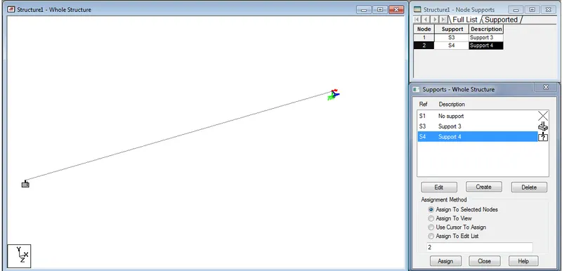
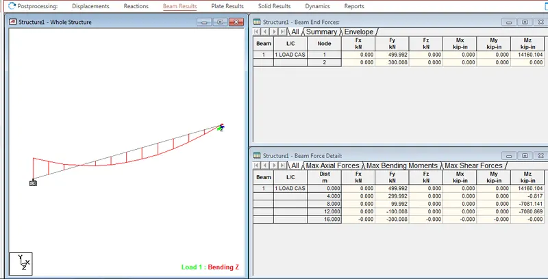
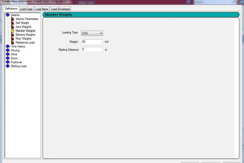
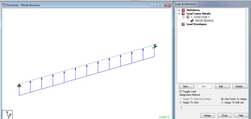
- A Point load at 50 Kn at the mid point
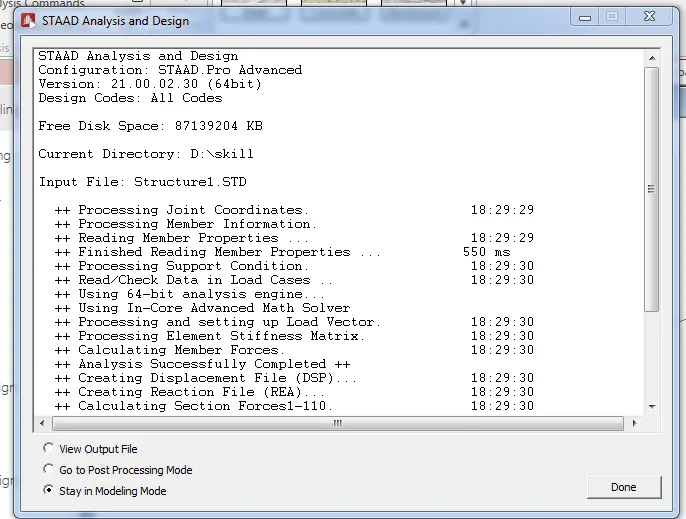
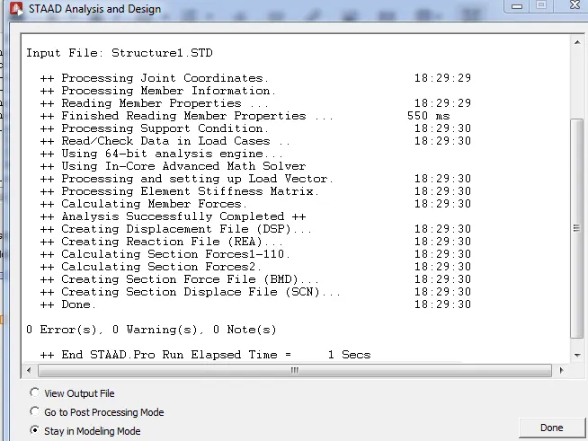
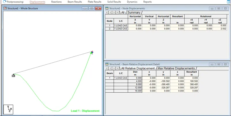
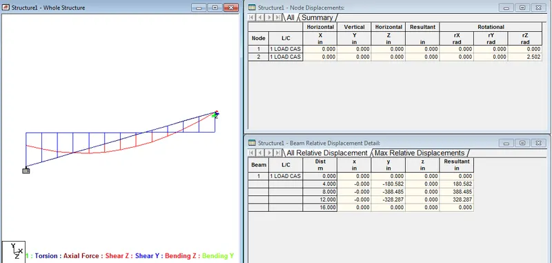
- Draw SFD AND BMD