Sketch a G+1 residential plan according to Vaastu Shastra and Calculation of Loads as per IS code
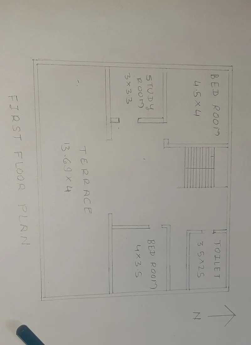
- Dimension of First floor plan
- Bedroom:4 X 3.5
- Toilet : 3.5 X 2.5
- Study room : 3 X 3.3
- Terrace : 13.69 X 4
- Bed room : 4.5 X 4
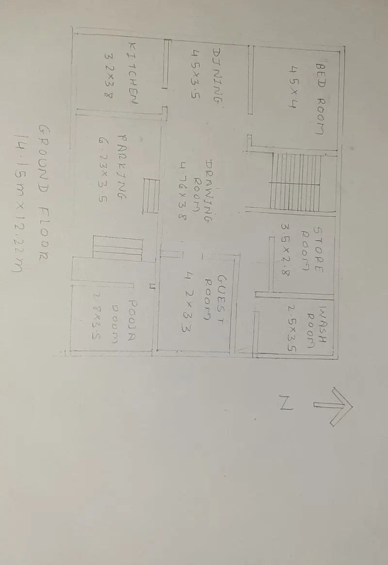
- Dimenaion of ground floor plan
- Bed room : 4.5 X 4
- Dining : 4.5 X 3.5
- Parking: 6.23 X 3.5
- Pooja room : 2.8 X 3.5
- Store room : 3.5 X 2.8
- Wash room : 2.5 X 3.5
- Guest room : 4.2 X 3.3
- Drawing room : 4.76 X 3.5
- Other dimensions
- Thickness of external/internal wall: 0.23mm
- Thickness of slab:0.25mm
- DImension of column:0.3 X 0.3
- Height of wall of ground floor:4m
- Height of wall of first floor
- Calculation of dead column
- DL of column
- Height of column = ( slab thickness*2)+ height of wall for ground floor +height of wall fpor first floor
=0.25*2+4+3.5
= 0.72
- Unit weight of rcc = 25 Kn/m3
- Dl of one column=0.72*25
- =18KN
- Dl of beams
- Volume of beam =0.3*0.45*1
=0.135
- Unit wt of rcc=25Kn/m
- Dl of beam =25 X 0.135
- =3.375KN
- Dl of slabs
- Thickness of slab=0.25
- Unit wt of rcc=25KN/m2
- Total volume of slab=1*1*0.25
=0.25
- Dl of slab=0.25*25
=6.25KN
- Dead load of wall
- Thickness of external/internal wall=0.23
- Unit wt ofbrick masonary=20KN/m3
- height of ground floor plan=4m
- DL of ground floor wall =Volume of wall per meter length*unit wt of brick masonary
=4*0.23*1*20
=18.4kN
- Height offirst floor wall=3.5m
- Dl of first floor wall per unit meter length=volume of wall per meter length*unit wt of brick masonary
=3.5*0.23*1*20
=16.1KN
- Total weight of ground floor and first floor wall per unit meter legth=34.45KN
- Live load calculation
AS per IS 875 part 2 for residential building live load are taken as
- Living and dining=2KN/m2
- Kitchen =2KN/m2
- Bed room =2KN/m2
- Wash room =2KN/m2
- Toilet =2Kn/m2
- Store room =2Kn/m2
- Terrace =3KN/m2
- Stair case =3Kn/m2
- Wind load calculation
- If the height of building is more than 10m then building needs to be designed for wind load
- But in this case , Height of building is 8m thus, wind load need not be considered
- The names of structural drawings required to be preapared to the site for construction are
- Centre line drawing
- Footing and column layout with reinforcement details
- Column schedule with reinforcement details
- Plinth beam layout with reinforcement detail
- Each floor beam layout with reinforcement details
- Lift pit abd head room with reinforcement details
- Floor plan
- Foundation plan
- Roof slab layout Column layout
- Column sections
- Septic tank details
- Overhead water tank details
- Furniture plan
- Road drainage plan
- Setting out plan
- section drawings of building
- plumbing details
- Electrification details