Creation of geometries by Coordinate system methods using AutoCad
AIM: To create diffrent geometrics shape given above by coordinate system using line and circle tool
INTRODUCTION:
COORDINATE SYSTEM:It is a method which allow to define the placement of points to determine the position of point/geometricsshape.This system is mainly of two types thy are
ABSOLUTE COORDINATE :It is a cartesian form where points are entered at some distance in X and Y axis with respect to origin
RELATIVE COORDINATE SYSTEM:In this the reference point is the previous point in the drawing not related to origin
- RELATIVE RECTANGULAR COORDINATE : Rectangular coordinate specify each point in a pair of numerical in X and Y axis. In command line it is represented as @x axis distance eg.@5,10
- Relative polar coordinate :Polar coordinate specify one radial distance and one angle of particular point w.r.t previous point .In command line it is entered as @distance
DIRECT DISTANCE METHOD:It is another method used for drawing in autocad.In this method user can draw any object any object just by pointing cursor in required direction and by entering distance value
- LINE TOOL:Line command can be searched by entering L in command box or from ddraw panel in ribbon. line is draw using several random point it is used to draw required shapes with help of coordinate system
- CIRCLE TOOL: Circle command can be searched in command line by entering C or from draw panel in ribbon .Circle can be drawn wih 5 diffrent option
- Circle and radious :First step is to enter the center coordinate and enter radious value
- Circle and diameter : Enter centre coordinate and enter diameter value
- Circle with 2 Points:Circle is drawn by selecting 2 points
- Circle with 3 points:Circle is drawn by selecting 3 points
- Tan,Tan,Radious:Circle is drawn by selecting 2 tangents and entering required radious
- Tan,Tan,tan:Circle is drawn by entering 3 tangents points on the line
PROCEDURES:Creation of drawing sheet
- Go to start menu click Autocad
- Click on start drawing
- From command line enter start up:1
- Go to application menu select new
- Select imperial system and start from scratch option
- From advance setting select decimal option
- Set angle unit as decimal degree
- Enter limits in command line
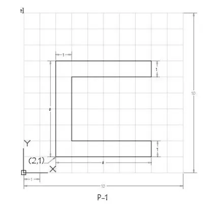
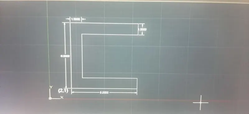
- CREATE THE GIVEN GEOMETRY GIVEN IN P-1
- Using absoulute coordinate system
- Select the line tool from command box by entering L
- Specify atarting point (2,1) in command box
- Specify second coordinate point (8,1)
- Specify third coordinate point (8,2)
- Specify fourth coordinate point (3,2)
- Specify fifth coordinate point (3,6)
- Specify sixth coordinate point (8,6)
- Specify seventh coordinate point (8,7)
- Specify eigth coordinate point (2,7)
- Click close in command box
- RESULT
2.Creating the Geometry of P-2
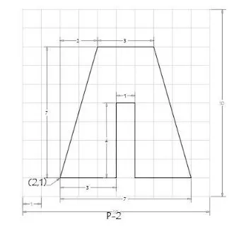
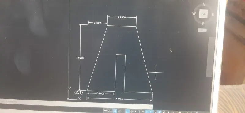
Using the relative rectangular coordinate system
- Select the line command by enterinf L
- Specify starting point 1 As (2,1)
- Specify next coordinate point 2 as @3,0 in command line
- Specify next coordinate point 3 as @0,4 in command line
- Specify next coordinate point 4 as @1,0 in command line
- Specify next coordinate point 5 as @0,-4 in command line
- Specify next coordinate point 6 as @3,0 in command line
- Specify next coordinate point 7 as @-2,7 in command line
- Specify next coordinate point 8 as @3,0 in command line
- Click on close command line
- RESULT
3.Creating the geometry in p-4 using absoulute coordinate system
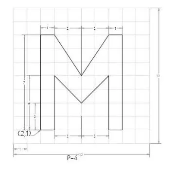
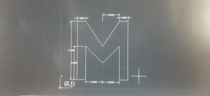
PROCEDURE:
- Select the line L from command box
- Specify the starting point 1 as (2,1) in the command line
- Specify the next coordinate of point 2 (3,1) in the command line
- Specify the next coordinate of point 3 (3,5) in the command line
- Specify the next coordinate of point 4 (5,3) in the command line
- Specify the next coordinate of point 5 (7,5) in the command line
- Specify the next coordinate of point 6 (7,1) in the command line
- Specify the next coordinate of point 7 (8,1) in the command line
- Specify the next coordinate of point 8 (8,8) in the command line
- Specify the next coordinate of point 9 (7,8) in the command line
- Specify the next coordinate of point 10 (5,5) in the command line
- Specify the next coordinate of point 11 (3,8) in the command line
- Specify the next coordinate of point 12 (2,8) in the command line
- Click close on command line
4.CREATING THE GEOMETRY OF P-5 USING THE DIRECT DISTANCE METHOD
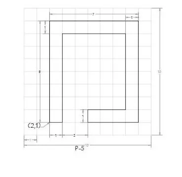
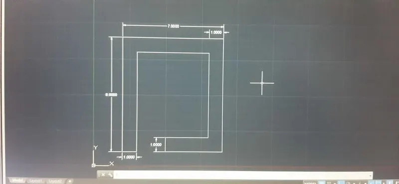
PROCEDURE:
- Select the line tool from command box
- Specify the starting coordinateof point 1 as (2,1) in the command line
- Enter the length of point 2 as 1 in the command line positive x axis
- Enter the length of point 3 as 7 in the command line positive y axis
- Enter the length of point 4 as 5 in the command line positive x axis
- Enter the length of point 5 as 7 in the command line negative y axis
- Enter the length of point 6 as 3 in the command line negative x axis
- Enter the length of point 7 as 1 in the command line negative y axis
- Enter the length of point 8 as 4 in the command line positive x axis
- Enter the length of point 9 as 8 in the command line positive y axis
- Enter the length of point 10 as 7 in the command line negative x axis
- click close on command line
- Creating the geometry of p-7 using absolute coordinate system
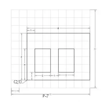
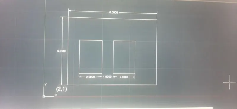
PROCEDURE:
- Select the line tool from command bar by entering L
- Specify the starting coordinate of point 1 as 2,1 in command line
- Enter the length of point 2 as (10,1) in the command line
- Enter the length of point 3 as (10,7) in the command line
- Enter the length of point 4 as (2,7) in the command line
- Click close in the command line
- Select the line tool again from command line
- Enter the length of point 5 as (3,2) in the command line
- Enter the length of point 6 as (5,2) in the command line
- Enter the length of point 7 as (5,5) in the command line
- Enter the length of point 8 as (3,5) in the command line
- Click close in the command line
- Select the line tool again from command line
- Enter the length of point 9 as(6,2) in the command line
- Enter the length of point 10 as (8,2) in the command line
- Enter the length of point 11 as (8,5) in the command line
- Enter the length of point 12 as (6,5) in the command line
- Click close in the command line
- CREATING THE GEOMETRY OF P-8 USING THE DIRECT DISTANCE ENTRY METHOD
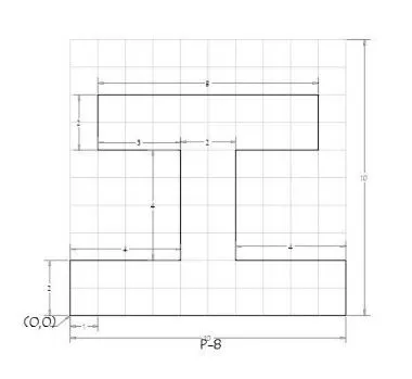
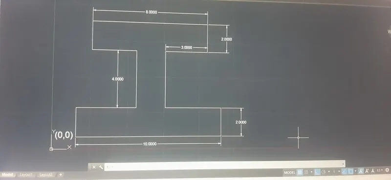
PROCEDURE:
- Select the line toolfrom command bar by entering L
- Specify the starting coordinate of point 1 as (0,0) in the command line
- Enter the length of point 2 as 10 in the command line positive x axis
- Enter the length of point 3 as 2 in the command line positive x axis
- Enter the length of point 4 as 4 in the command line positive x axis
- Enter the length of point 5 as 4 in the command line positive x axis
- Enter the length of point 6 as 3 in the command line positive x axis
- Enter the length of point 7 as 2 in the command line positive x axis
- Enter the length of point 8 as 8 in the command line positive x axis
- Enter the length of point 9 as 2 in the command line positive x axis
- Enter the length of point 10 as 3 in the command line positive x axis
- Enter the length of point 11 as 4 in the command line positive x axis
- Enter the length of point 12 as 4 in the command line positive x axis
- Click close in the command line
- CREATING THE GEOMETRY OF P-9 USING ABSOLUTE COORDINATE SYSTEM
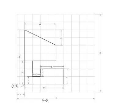
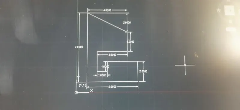
PROCEDURE
- Select the line tool from command barby entering L
- Specify the coordinate of point 1 as (1,1) in the command line
- Specify the next coordinate point 2 as (6,1) in the command line
- Specify the next coordinate point 3 as (6,3) in the command line
- Specify the next coordinate point 4 as (3,3) in the command line
- Specify the next coordinate point 5 as (3,2) in the command line
- Specify the next coordinate point 6 as (2,2) in the command line
- Specify the next coordinate point 7 as (2,4) in the command line
- Specify the next coordinate point 8 as (5,4) in the command line
- Specify the next coordinate point 9 as (5,6) in the command line
- Specify the next coordinate point 10 as (1,8) in the command line
- Click close in the command line
- CREATING THE GEOMETRY OF P-10 USING ABSOULUTE COORDINATE SYSTEM
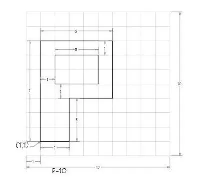
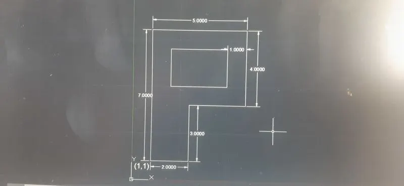
- PROCEDURE
- Select the line tool from command bar by entering L
- Specify the starting point 1 as (1,1) in the command line
- Specify the next coordinate point 2 as (3,1) in the command line
- Specify the next coordinate point 3 as (3,4) in the command line
- Specify the next coordinate point 4 as (6,4) in the command line
- Specify the next coordinate point 5 as (6,8) in the command line
- Specify the next coordinate point 6 as (1,8) in the command line
- Click close in the command box
- Select the line tool from command bar by entering L
- Specify the next coordinate point 7 as (2,5) in the command line
- Specify the next coordinate point 8 as (5,5) in the command line
- Specify the next coordinate point 9 as (5,7) in the command line
- Click close in the command box
- CREATING THE GEOMETRY PROFILE WOD USING RELATIVE POLAR COORDINATE SYSTEM
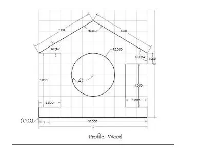
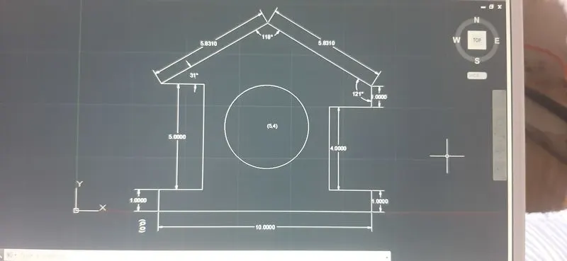
- PROCEDURE
- Select the line tool from command bar by entering L
- Specify the Starting coordinate of point 1 as (0,0) in the command line
- Specify the next coordinate point 2 as @10<0 in the command line
- Specify the next coordinate point 3 as @1<90 in the command line
- Specify the next coordinate point 4 as @2<180 in the command line
- Specify the next coordinate point 5 as @4<90 in the command line
- Specify the next coordinate point 6 as @2<0 in the command line
- Specify the next coordinate point 7 as @1<90 in the command line
- Specify the next coordinate point 8 as @5.83<121 in the command line
- Specify the next coordinate point 9 as @5.83<31 in the command line
- Specify the next coordinate point 10 as @2<0 in the command line
- Specify the next coordinate point 11 as @5<270 in the command line
- Specify the next coordinate point 12 as @2<180 in the command line
- Click close in the command box
- Select the circle and radious tool from draw panel
- Enter the circle of radious of 2 in commad line
- CRREATING THE GEOMETRY OF QUEEN POST TRUSS USING RELATIVE POLAR COORDINATE SYSTEM
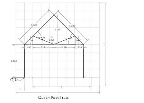
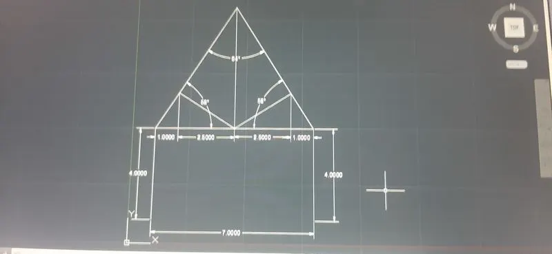
t
- PROCEDURE
- Select the line tool from commnd bar
- Specify the point 1 as (1,1) in the command line
- Specify the point 2 as @4<90 in the command line
- Specify the point 3 as @5<90 in the command line
- Specify the point 4 as @5<90 in the command line
- Specify the point 5 as @4<90 in the command line
- Press ESC to end the command line
- Press ENTER to repeat the line command
- Specify the point 6 as (1,5) in the command line
- Specify the point 7 as (2,5) in the command line
- Specify the point 8 as @1<90 in the command line
- Specify the point 9 as @2<215 in the command line
- Specify the point 10 as @2<45 in the command line
- Specify the point 11 as @1<270 in the command line
- Press ESC to cancel the line command
- CREATING THE GEOMETRY OF MONO PITCH USING ABSOLUTE COORDINATE SYSTEM
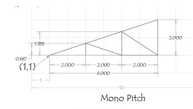
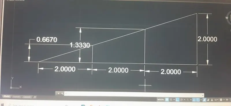
- PROCEDURE
- Select the line tool from command bar by entering L
- Specify the point 1 as (1,1) in the command line
- Specify the next point 2 as (7,1) in the command line
- Specify the next point 3 as (7,3) in the command line
- Specify the next point 4 as (3,1) in the command line
- Specify the next point 5 as (3,0.667) in the command line
- Specify the next point 6 as (5,1) in the command line
- Specify the next point 7 as (5,1.333) in the command line
- Specify the next point 8 as (7,1) in the command line
- Press ESC to cancel the line command