Week 1 Challenge
Week 1 Challenge
Jagadeep.M.M
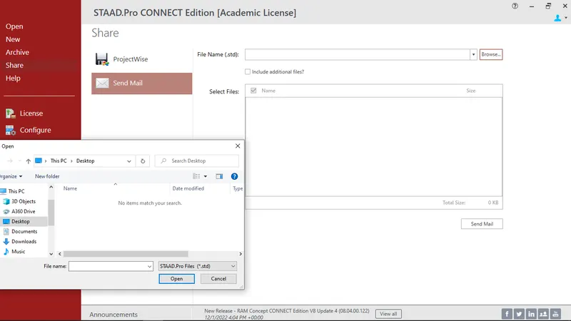
1. 1. Write the steps involved to upload a .std file through web mail?
Ans:
Open the staad pro software & click the share option,then click the send mail option & select the file name by clicking on the browse and select files by name and send the mail the by clicking send mail.
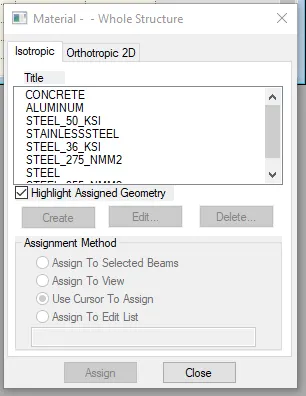
2. Name the different materials that can be designed using STAAD Pro.
Ans:
Concrete
Steel
Stainless steel
Aluminium
Timber
3. Is it possible to capture images in STAAD Pro? If yes how?
Ans:
Yes it is possible to capture images in Staad pro.
Click the utilities tab you will find a take picture option using this option we can capture a image.

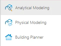
4. Name the three ways by which you can create a model.
Ans:
Analytical Modeling
Physical Modeling
Building Planner
5. Write the steps followed to assign properties in a model.
Ans:
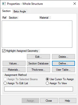
Go to properties tab in that select define and define the Rectangle beam shape and size after defining select the beam and select assign to selected beams and click on Assign To View.
2. 1. Name any six design parameter involved in RCC design.
Ans:
E - Modulus of elasticity
Poisson's ratio
Density
Yield strength of the steel- Fy
Ultimate tensile strength - Fu
Effective length factor - Kx, Ky, Kz
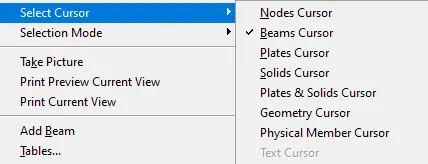
2. What are the different cursor types available in STAAD Pro?
Ans:
Nodes Cursor
Beams Cursor
Plates Cursor
Solids Cursor
Plates & Solids Cursor
Geometry Cursor
Physical Member Cursor
3. How will you generate different views for a model? State the steps involved.
Ans:
Click the view tab and choose the icon for isometric view, top view, bottom view, left view, front view, right view, back view.

4. Explain the procedure to define a “Simply Supported” condition in STAAD Pro.
Ans:
Create the two nodes and draw a beam(Add beam option) then define properties and go to supports select create and choose pinned support for both the nodes to make it act like Simply Support beam.

5. Name any five topics that you will include while creating DBR.
Ans:
Name of the project & the location of the project
Structural layout
Introduction to the construction methodology
Quality Assurance & Quality control
Budget of the project
6. Describe the term “Multi material design” of STAAD Pro.
Ans:
In buildings has different types of material like timber, steel, aluminium, concrete etc which is used for different purpose. The term multi-material design is typically used to define the structure that is designed by implementing more than one structural material.
3. 1. Name the structure systems in STAAD Pro? Explain each system?
Ans:
- Space
- Plane
- Frame
- Truss
- Space has a 3D, so that it can be X,Y & Z plane in geometry, loading and deformation. Any kind of the joints and restrain can be given to the modal i.e., assign as a space.
- Plane the geometry is majorly in 2D accordingly the loading and deformation are also in the 2D plane i.e., mostly X&Y plane and any type of joints can be assigned here in the plane structural system.
- Frame also 2 dimensional in nature the only changes that the loading is perpendicular to X&Z and accordingly the deformation is also perpendicular again here any kind of joints can be assigned to the frame structural system.
- Truss geometry can be in any direction. the truss can take only axial load and it cannot have any bending or shear so the geometry, loading and deformation can all be in all 3 planes but when it comes to a joint or restraint it can only take a Pinned restrain where in the translational movement is the restricted one but the moment is release.
2. Explain the coordinate system adopted in STAAD Pro software.
Ans:
Global axis and local axis coordinate system adopted in staad pro which is a three-dimensional analysis system.
In global axis X,Y&Z coordinate are fixed and not variable.
In local axis X,Y&Z coordinate is variable and depends on member orientation.
3. Elaborate DBR and its uses.
Ans:
DBR – Design Basis Report. It is used to specify and compile the data required for analysis and design of structural elements of the project. It depicts the assumptions and specifications that are being used to develop the documents for a project. It will also help to avoid the scope creep that affect the project schedule and budget.
4. Explain the different types of analysis options in STAAD pro.
Ans:
Member imperfection analysis
Pushover analysis
Linear static analysis
Second order analysis
Non-Linear analysis
5. Explain the difference between Fixed and Fixed But condition.
Ans:
Fixed condition in the STAAD.Pro software is the condition where all the six degrees of freedom that is Horizontal or Vertical or moment are fixed
Fixed end condition in the STAAD.Pro software can be customized by its end condition accordingly, end conditions can be changed it is not restrained.
Practical
1. Create a STAAD Model with the following Specification
a. A beam of span 16m
b. Support : Fixed on one end and Roller support(Horizontal) on the other end
c. A point load of 50 kN at the mid-point
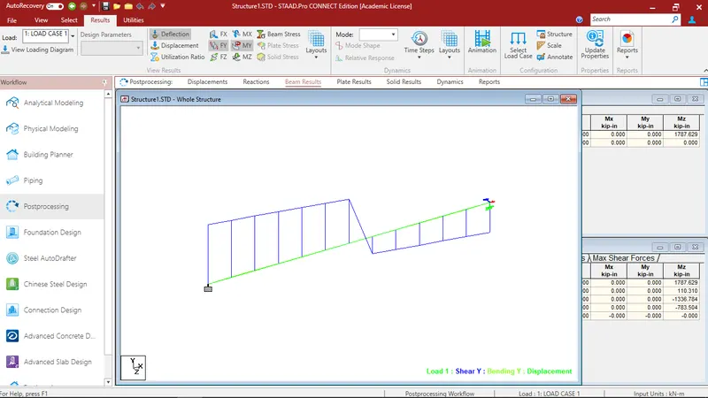
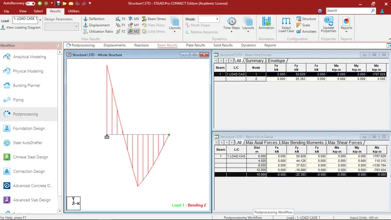
d. Draw SFD and BMD using software
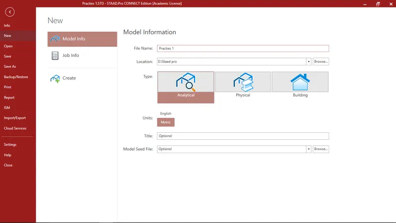
- Open the stadd pro sofware.
- Add the file name & location.
- Click the create option.
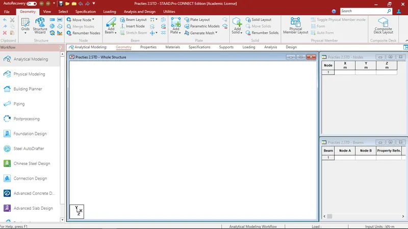
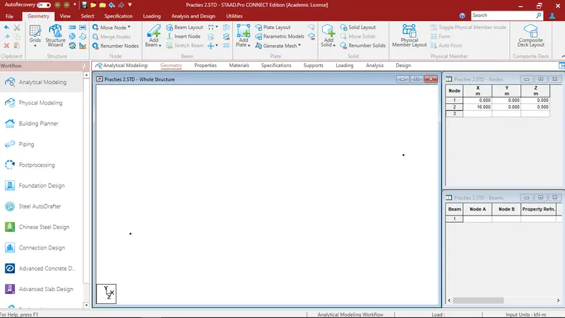
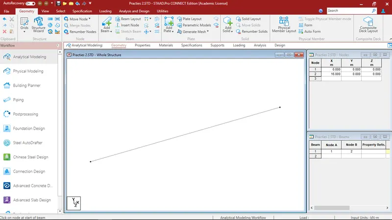
- enter the beam node 1as X=0 & node 2 as X=16
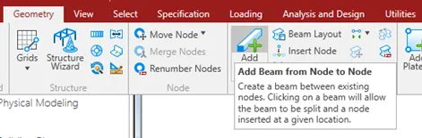
- In geometry click on the Add beam option & draw the beam one node to another node.
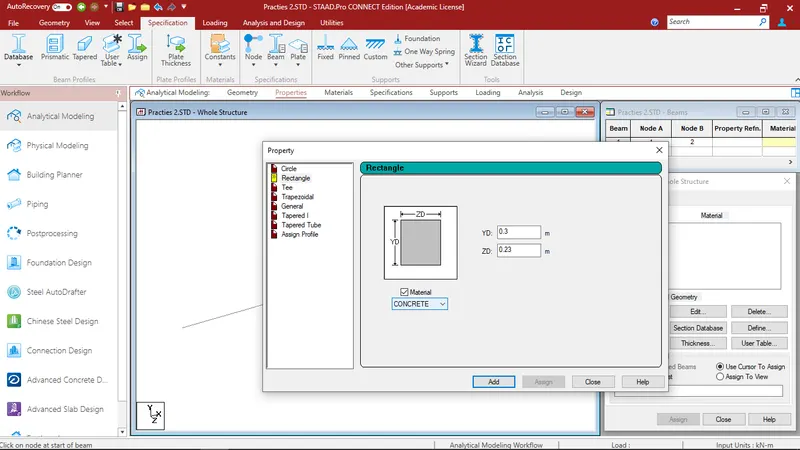
- Click the properties & click on the Define & add the rectangle beam size.
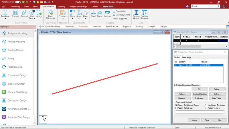
- After that select the beam & click the Assign.
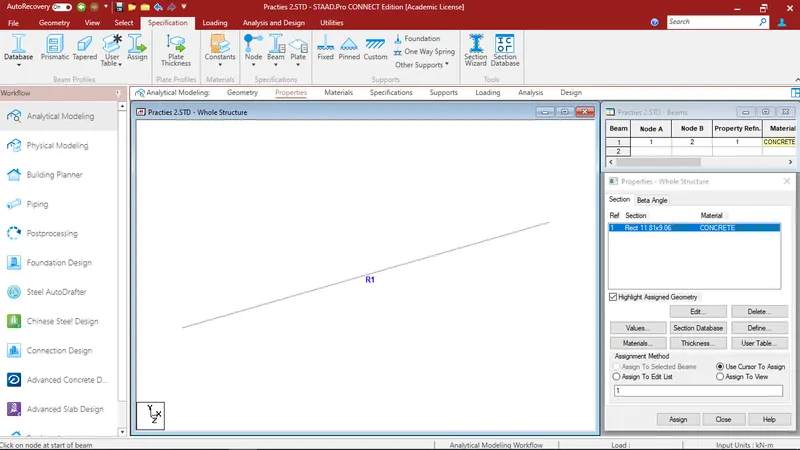
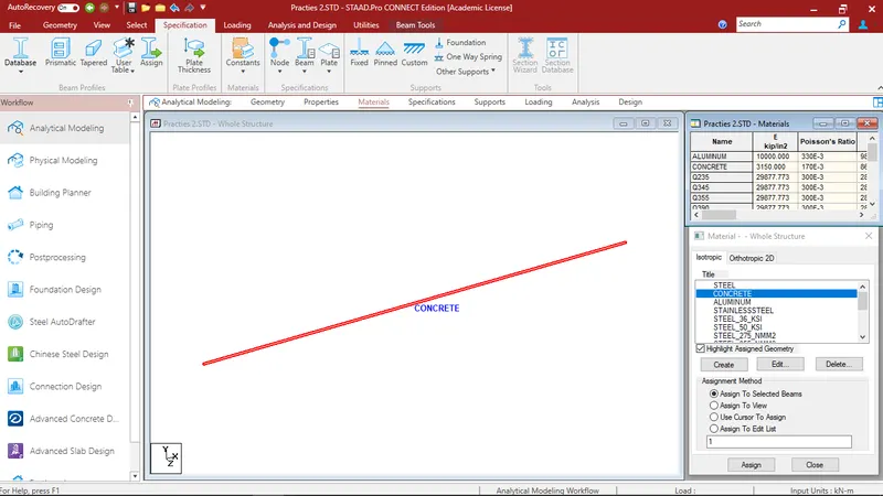
- Click on the materials & select the concrete.
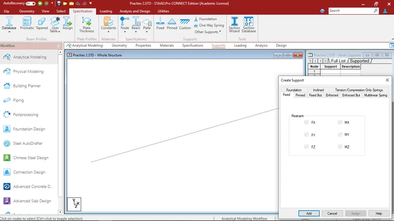
- Click the supports & click the create option.
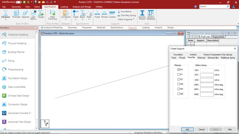
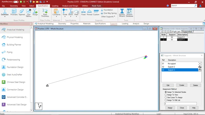
- One end is fixed & another end is fixed but suppport.
- Assign to selected node & assign it.
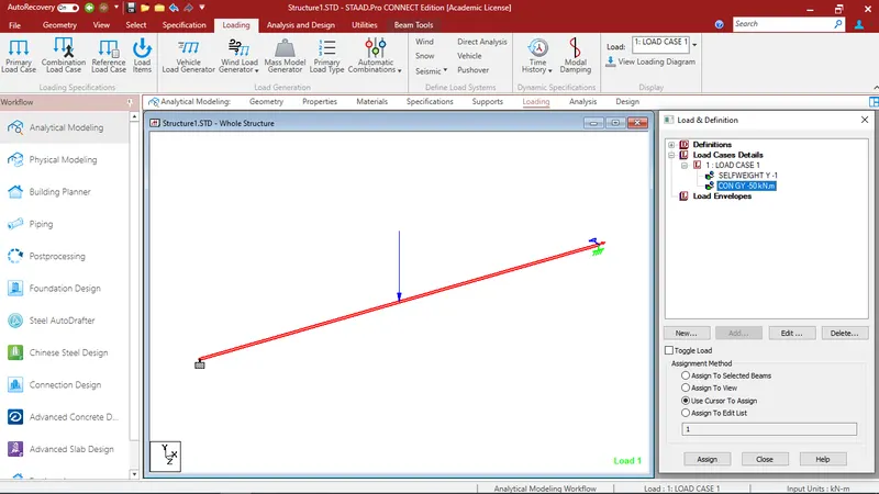
- click the loading tab go to load cases details and add dead load and assign the load.
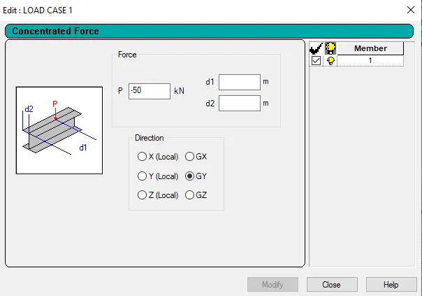
- Click the on the mid load to provide the point load as -50KN.
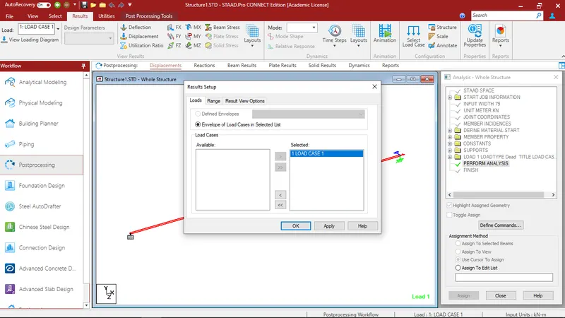
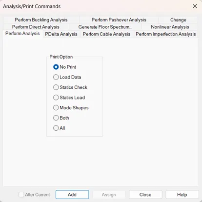
- Click the analysis tab and do performance analysis and assign it and then analysis and design tab and run the analysis.
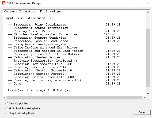
- Click on the post processing & click the load case 1.
- result will be visible.
- Click the beam results & click the SFD & BMD.