Drafting of various geometries using Chamfer, Fillet tool in AutoCad
DRAFTING OF VARIOUS GEOMETRIES USING CHAMFER,FILLET TOOL IN AUTOCAD
Jagadeep.MM
AIM:
To drafting of various geometries using chamfer,fillet tool in Autocad.
INTRODUCTION:
- AutoCad offers various tools to perform different tasks.
- The various tools which are used for drafting in this project are brifly described here.
Various commands & tools used are:
- Chamfer
- Fillet
- Offset
- Rotate
- Object snapping
- Trim & Extend
- Lengthen
- Mirror
- Join
Chamfer:
- An angled line that meets the endpoints of two straight 2D objects.
- A sloped transition between two surface or adjacent faces on a 3D solid.
The distances & angles that you specify are applied in the order that you select the objects.
Fillet:
- The fillet tool helps from round corner between any two entities that from a sharp vertex.
- A round or fillet can be created between two objects of the same or different object types:2D polylines,arcs,circles,ellipses,elliptical arcs,lines,rays splines,& xlines.
- If the two selected objects are on the same layer,the arc defined is created on the layer. Otherwise the arc is created on the current layer. The layer affects object properties including colour & line type.
Offset:
- Creates concentric circles,parallel lines, & parallel curves.
Rotate:
- Used to rotate objects in our drawing around a specified base point.
- To determine the angle of rotation, we can enter an angle value, drag using the cursor,or specify a reference angle to align to an absolute angle.
Object snap:
- Object snaps provide a way to specify precies locations on objects whenever you are prompted for a point within a command.
Trim & Extend:
Trim:
- Trim objects is used to remove the objects, which meet the edges of other objects.
- It is used to remove extra lines or extra parts of an object.
- Command used:TR
Extand:
- The extend command is used to extand the selected boundaries or edges.
- The objects are extended so that the edges of other objects can be converged.
- Command used:EX
Lengthen:
- Changes the length of objects & the included angle of arcs.
- You can specify chanes as a percentage, an increment, or as a final length or angle.Lengthen is an alternative to using Trim or Extend.
Mirror:
- Create a mirrored copy of selected objects.
- We can create objects that represent half of a drawing, select them, & mirror them across a specified line to create the other half.
Join:
- Join the endpoints of linear & curved objects to create a single object.
- Combines a series of finite linear & open curved objects at their common endpoints to create a single 2D or 3D object. The type of object that results depends on the types of objects selected the type of object selected first & whether the objects are coplanar.
Arc:
- To create an arc, you can specify combinations of center, endpoint,start point,radius,angle,chord length,& direction values. Arcs are drawn in a counter clockwise direction by default. Hold down the Ctrl key as you drag to draw in a clockwise direction.
Procedure:
Drawing-1
- Open autocad softwere, type QNew incommand box,press enter.
- Select default setting as imperial setting.
- drawing units setting as length=(Decimal),precision=0.00
- Type the command box Dimension style manager & press enter.
- enter modify-enter primary units-unit format=Decimal, precision=0.0,enter Ok
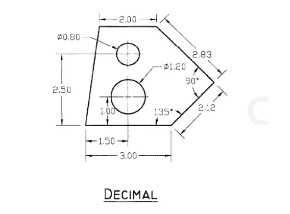
- choose the line tool or type line incommand box & specify first point as(1,1) press enter.
- specify the next point as @3,0 & press enter.
- specify the next point as @2.83<135 press enter.
- specify the next point as @-2,0 press enter, press the close option in command box press enter.
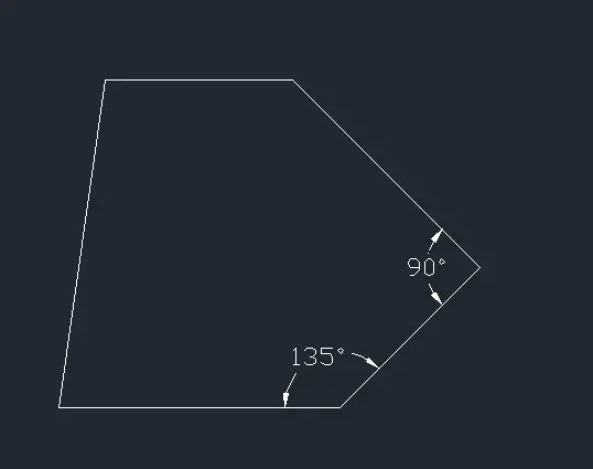
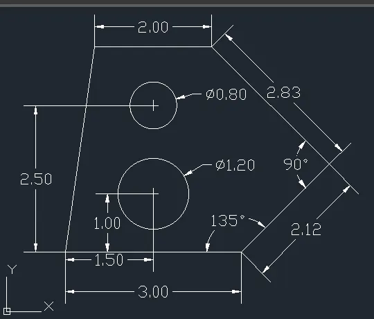
- Againe choose the circle in draw panel select the center,diameter & press enter.
- specify the center point of the circle is 2.5,2 & press enter.
- specify the radius of the circle is 1.2 & press enter.
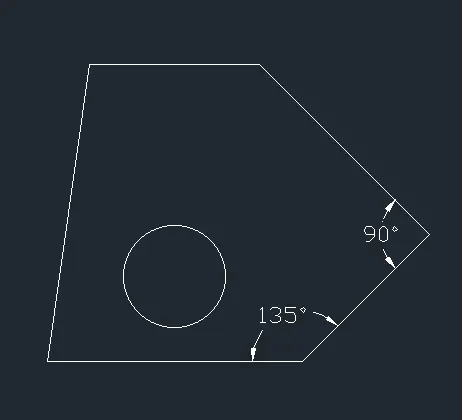
- Againe choose the circle in draw panel select the center,diameter & press enter.
- specify the center point of the circle is 2.5,3.5 & press enter.
- specify the radius of the circle is 0.8 & press enter.
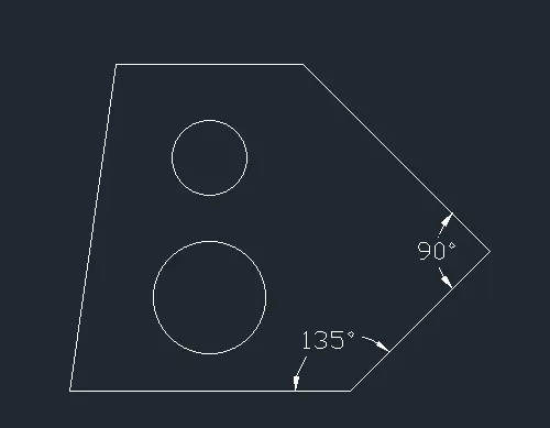
- complition of drawing give dimensions using dimension tool.use the tool Linear,Aligned & diameter,angular.
Result:
Procedure:
Drawing-2
- Open autocad softwere, type QNew incommand box,press enter.
- Select default setting as imperial setting.
- units-architectural-precision-0'0"- feet-ok
- Type the command box Dimension style manager & press enter.
- enter modify-enter primary units-unit format=architectural, precision=0'0",enter Ok
- Type the command box-Drafting setting click on snap & grid option,snap spacing=1',grid spacing=1',major line every=10.
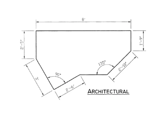
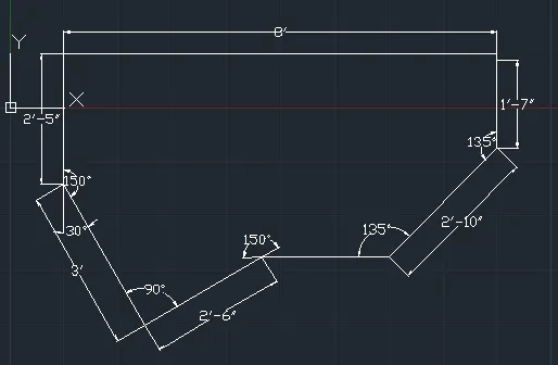
- choose the line tool or type line incommand box & specify first point as(1',1') press enter.
- specify the next point as @8',0 & press enter.
- specify the next point as @0,-1'9" press enter.
- specify the next point as @2'10"<225 press enter.
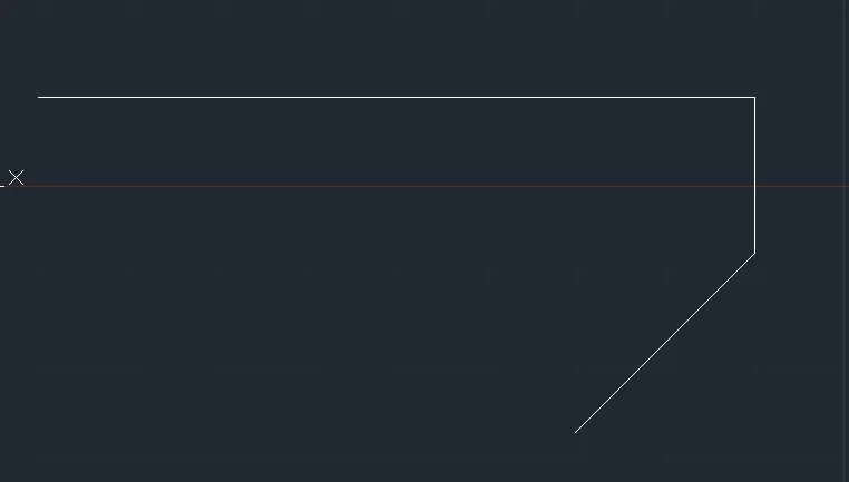
- Againe choose the line option press enter.
- specify the first point as 1',1' press enter.
- specify the next point as @0,-2'5" press enter.
- specify the next point as @3'<300 press enter.
- specify the next point as @2'6"<30 press enter & close option in command box press enter.
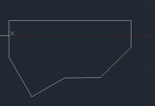
- complition of drawing give dimensions using dimension tool.use the tool Linear,Aligned & angular.
Result:
Procedure:
Drawing-3
- Open autocad softwere, type QNew incommand box,press enter.
- Select default setting as imperial setting.
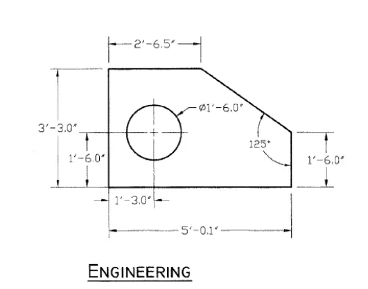
- units-engineering-precision-0'0"- feet-ok
- Type the command box Dimension style manager & press enter.
- enter modify-enter primary units-unit format=engineering, precision=0'0",enter Ok
- Type the command box-Drafting setting click on snap & grid option,snap spacing=1',grid spacing=1',major line every=10.
- click on polar traking on & ortho will be off
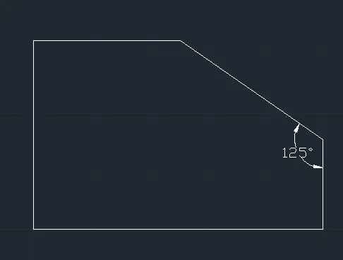
- choose the line tool or type line incommand box & specify first point as(1',1') press enter.
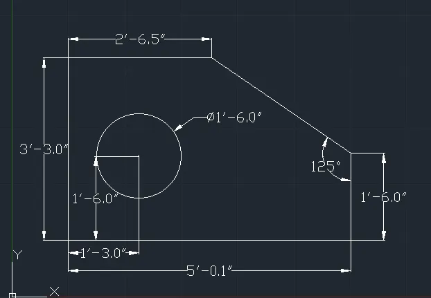
- specify the next point as 3'3.0" & press enter.
- specify the next point as 2'6.5" & press enter.
- againe choose the line tool specify the first point as(1',1') press enter.
- specify the next point as 5'0.1" & press enter.
- specify the next point as 1'6.0" & press enter close the option incommand box & press enter.
- Againe choose the circle in draw panel select the center,diameter & press enter.
- specify the center point of the circle is 2'3.0",2'6.0" & press enter.
- specify the radius of the circle is 1'6.0" & press enter.
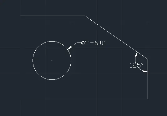
- complition of drawing give dimensions using dimension tool.use the tool Linear, & angular.
Result:
Procedure:
Drawing-4
- Open autocad softwere, type QNew incommand box,press enter.
- Select default setting as imperial setting.
- unit-decimal-precision-0.00-ok
- Type the command box Dimension style manager & press enter.
- enter modify-enter primary units-unit format=decimal, precision=0.00,enter Ok
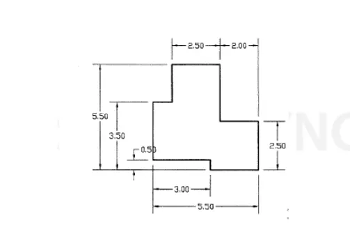
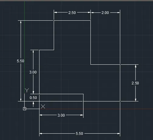
- choose the polyline tool or type polyline incommand box & specify first point as(1,1) press enter.
- draw 3m line in +ve Y axis, 1m line in +ve X axis, 2m line in +ve Y axis, 2.5m line in +ve X axis, 3m line in -ve Y axis, 2m line in +ve X axis, 2.5m line in -ve Y axis ,2.5m line in -ve X axis, 0.5m line in +ve Y axis, 3m line in -ve X axis.
- complition of drawing give dimensions using dimension tool.use the tool Linear, & angular.
Result:
Procedure:
Drawing-5
- Open autocad softwere, type QNew incommand box,press enter.
- Select default setting as imperial setting.
- unit-decimal-precision-0.00-ok
- Type the command box Dimension style manager & press enter.
- enter modify-enter primary units-unit format=decimal, precision=0.00,enter Ok
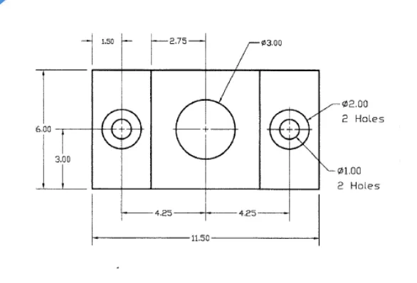
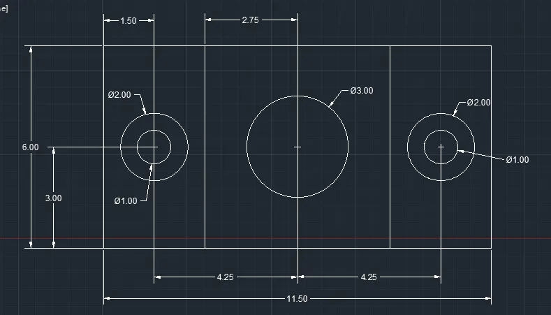
- choose the line tool:6m line in +ve Y axis, 11.5m line in +ve Xaxis ,6m line in -ve Y axis & 11.5m line in -ve X axis.
- choose the offset tool:select the 6m line & press offset tool,specify the offset distance is 3m on both sides & 11.5m line at a distance of 3m
- choose the object snap keep midpoint,center,intersection & geometric center ON.
- choose the circle in draw panel select the center,diameter & press enter.
- Draw the circle at the center with diameter 3m.
- againe choose the circle:Draw concentric circles at the intersection of the offsetted line of diameter 1m & 2m on both the sides.
- choose the erase command to erase the offsets.
- complition of drawing give dimensions using dimension tool.use the tool Linear, & diameter.
Result:
Procedure:
Drawing-6
- Open autocad softwere, type QNew incommand box,press enter.
- Select default setting as imperial setting.
- unit-decimal-precision-0.00-ok
- Type the command box Dimension style manager & press enter.
- enter modify-enter primary units-unit format=decimal, precision=0.00,enter Ok
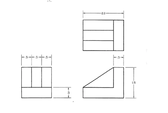
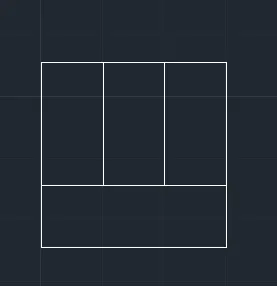
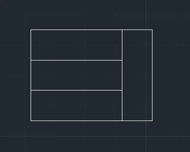
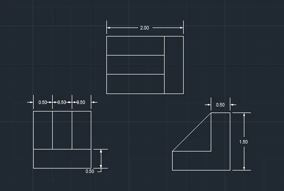
- choose the line tool & draw the line 1.5m horizontal & 1.5 vertival on both side.
- choose the offset tool & select the 1.5m line bottom horizontal & offset in 0.5m distance.
- choose the divide tool & select the 1.5m line top horizontal & enter the number of segment 3.
- choose the line tool join the divided lines.
- choose the line tool & draw the line 2m horizontal & 1.5 vertival on both side.
- choose the offset tool & select the 1.5m line back vertical & offset in 0.5m distance.
- choose the divide tool & select the 1.5m line front vertical & enter the number of segment 3.
- choose the line tool join the divided lines.
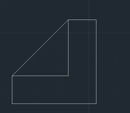
- choose the line tool & draw the line 1.5m horizontal & 1.5 vertival.
- choose the offset tool & select the 1.5m horizontal & give the offset of 0.5m , select the 1.5m vertical & give the offset of 0.5m.
- choose the line tool & draw the line in corner of line join.
- type the command trim & trim the unwanted lines.
- type the command line & join the corner in line tool.
- complition of drawing give dimensions using dimension tool.use the tool Linear.
Result:
Procedure:
Drawing-7
- Open autocad softwere, type QNew incommand box,press enter.
- Select default setting as imperial setting.
- unit-decimal-precision-0.00-ok
- Type the command box Dimension style manager & press enter.
- enter modify-enter primary units-unit format=decimal, precision=0.00,enter Ok
- choose the snap & grid tool or type in command box "ds" enter.
- snap spacing-X spacing & Y spacing=50m, gride spacing-X spacing & Y spacing=50m, major line every=5, OK.
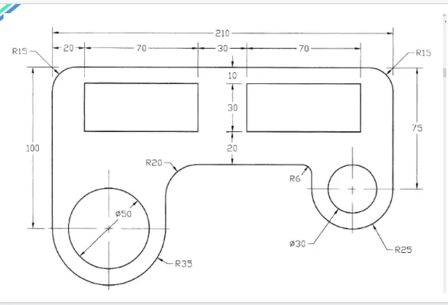
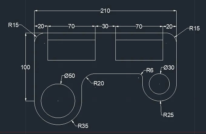
- Draw the circle radius 35& another circle with same center with diameter 50.command "c"specify centre & give radius.
- Draw the line with command line along diameter of the circle & then vertically upward give the distance as 100m,then + X axis distance of 210m & -Y axis distance of 75m.
- Draw the circle radius 25 in a bottom of 75m & another circle with same center with diameter 30. then move the two circle left side to tuch the 30 diameter circle 75m line.
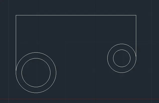
- Draw the offset in vertival direction 20,70,30,70 units in offset command.
- Draw the offset in horizontal direction 10,30,60 units in offset command.
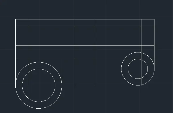
- Delete the offset & unwanted lines.
- Trim the unwanted lines.
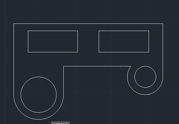
- command "fillet" click om radius & give the radius ,then select the two lines of which the corners are to be filleted.
- for the left & right side of the figure give 15 units as fillet radius.
- Give the fillet radius as 20 unit & 6 units in the bottom side.
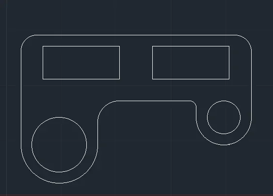
- complition of drawing give dimensions using dimension tool.use the tool Linear,radius,diameter.
Result:
Procedure:
Drawing-8
- Open autocad softwere, type QNew incommand box,press enter.
- Select default setting as imperial setting.
- unit-decimal-precision-0.00-ok
- Type the command box Dimension style manager & press enter.
- enter modify-enter primary units-unit format=decimal, precision=0.00,enter Ok
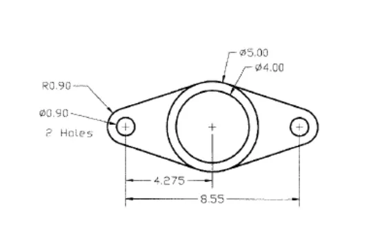
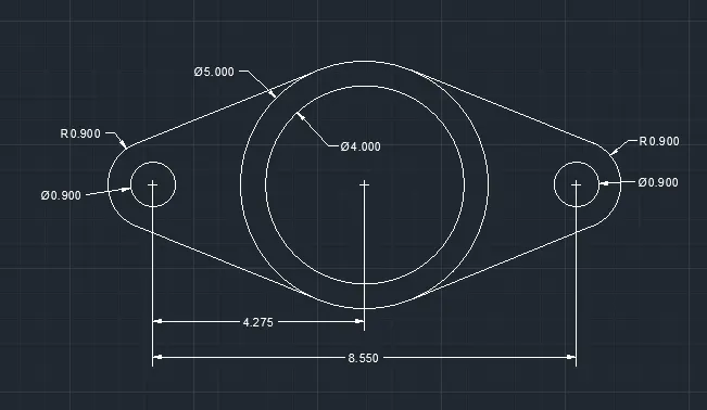
- draw the multiple point distance of 4.275m & copy the two multiple point to the distance of 4.275m.
- draw the center radius of 0.9 unit & center diameter of 0.9unit in a first multiple point & cpoy the radius & diameter third multiple point.
- draw the center diameter of 4 unit & 5 unit in a second multiple points.
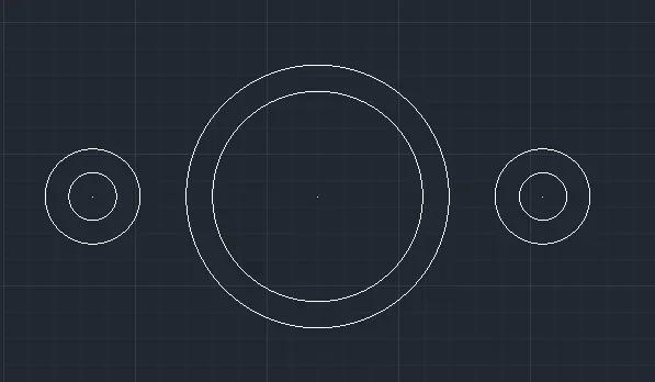
- Draw the polyline tangent to the first circle of radius 0.9 & second circle of diameter5 units i top & bottom on both sides.with "OSNAP" -ON.
- Delete the line drawn for reference & trim the unwanted part of circle by command "TR" specify the base object,select the tangent line -select the object to be trimmed -select the circle & enter.
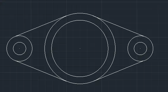
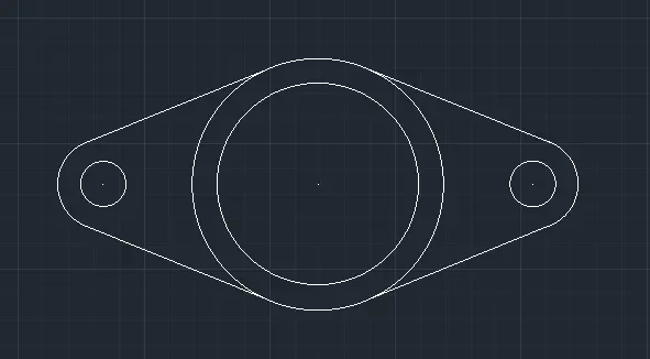
- complition of drawing give dimensions using dimension tool.use the tool Linear, Radius, diameter.
Result:
Procedure:
Drawing-9
- Open autocad softwere, type QNew incommand box,press enter.
- Select default setting as imperial setting.
- units-engineering-precision-0'0"- feet-ok
- Type the command box Dimension style manager & press enter.
- enter modify-enter primary units-unit format=engineering, precision=0'0",enter Ok.
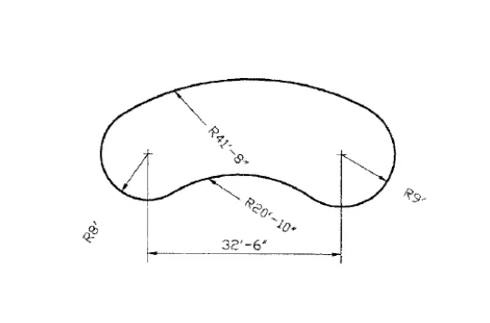
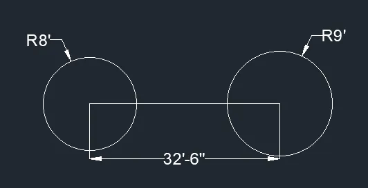
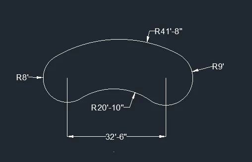
- Draw the line 32'6" then draw two circles of radius 8' & 9' with center as
- draw the dottom of the circle to give command box Tan-Tan radius.
- to draw the bottom of circle give the tan of first circle & second circle the specify the radius as 20'10" enter.
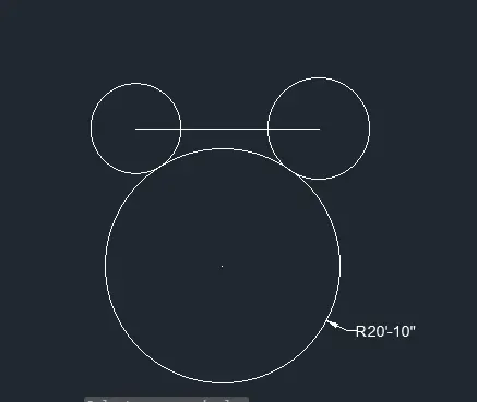
- Trim the rest of the figure to get arc & thus an arc of 20'10" wii be formed.
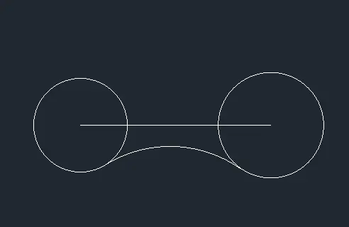
- To draw the upper curve.
- Draw a circle with radius 32'8"(41'8"-9'=32'8") with center same as that of radius 9' circle.
- Draw the another circle with radius 33'8"(41'8"-8'=33'8") with center same as that of radius 8' circle.
- Draw perpendicular lines from the bottom intersection of both circles and through the center to top of the circle of 8' & 9' which indicates the tangent points.
- Draw another circle with center as the intersecting point of the bottom circles & with radius 41'8".
- It passes through the tangent lines drawn earlier.
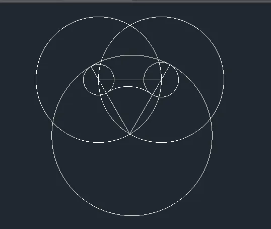
- Trim the unwanted circle & line.
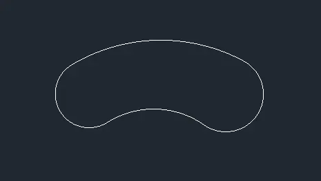
- complition of drawing give dimensions using dimension tool.use the tool Linear, Radius.
Result:
Procedure:
Drawing-10
- Open autocad softwere, type QNew incommand box,press enter.
- Select default setting as imperial setting.
- unit-decimal-precision-0.00-ok
- Type the command box Dimension style manager & press enter.
- enter modify-enter primary units-unit format=decimal, precision=0.00,enter Ok.
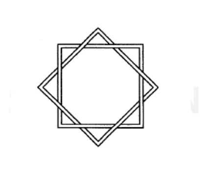
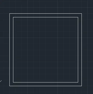
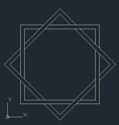
- Command "REC" specify the point where we need to draw-click on dimension -here i have taken as length=6 unita & breadth=6 units.
- Take the offset of 0.3 units inside the rectangle .
- copy the rectangle in another side.
- Rotate the second square by command "RO"-select the object -specify the base point-bottom point (first corner bottom point)& rotate it by angle 45 degree.
- with OSNAP on move the rectangle by command "M" select object -specify base point & is moved & placed on center of the first square by using osnap center on.
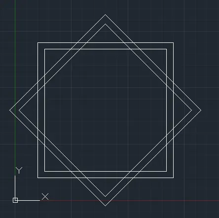
- Trim the overlapping lines alternatively by command "TR"-double enter.
Result:
Procedure:
Drawing-11
- Open autocad softwere, type QNew incommand box,press enter.
- Select default setting as imperial setting.
- units-engineering-precision-0'0"- feet-ok
- Type the command box Dimension style manager & press enter.
- enter modify-enter primary units-unit format=engineering, precision=0'0",enter Ok
- Type the command box-Drafting setting click on snap & grid option,snap spacing=1',grid spacing=1',major line every=10.
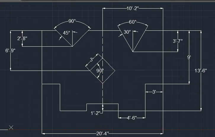
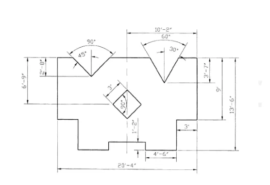
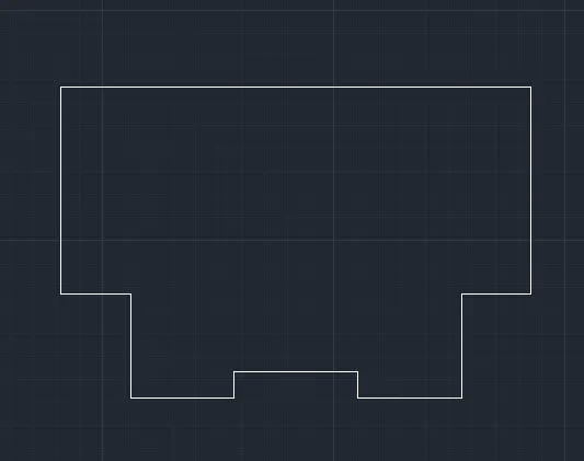
- command "L" give distance of 2'8"(10'2"-(4'6"+3') to +x axis.
- with cursor pointing to -Y direction give a distance of 1'2".
- with cursor pointing to+X direction draw a line of 4'6".
- with the cursor pointing to +Y direction draw a line of 4'6"(13'6"-9').
- draw 3' in X direction.
- draw 9' in +y direction.
- draw 10'2" -X direction.
- with command "M" mirror the image, select the object-select the base point & give the mirror line-& click NO so that the original object won't get erased.
- give offset line of distance 3'7" horizontaly by offset command "0".
- with midpoint of 10'2" draw a vertical line of length 3'7".
- draw lines on both sides such that the included angle is 60 degree 30 degree on both side of the vertical line.
- similarly on the other side, locate the midpoint ,draw a vertical line 2'8" & draw the inclined lines such that the included angle is 90degree.
- draw a line vertically downward from the midpoint of the object 10'2"& offset the top line at a distance of 6'9" so that the center point of the square is located.
- with the command "polygon" draw the a polygon of 4 sides, specify center & give radius as 1'5" circumscribed inside a circle.
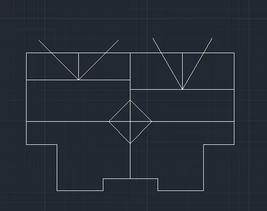
- Trim the unwanted lines.
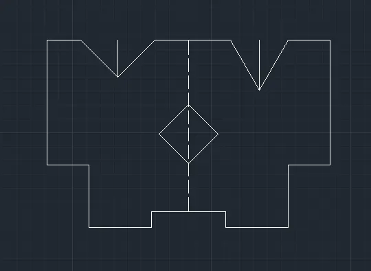
- complition of drawing give dimensions using dimension tool.use the tool Linear, Angular.
Result: