Creating a Floor plan, Footing detail and Isometric view using AutoCad
CREATING A FLOOR PLAN, FOOTING DETAIL & ISOMETRIC VIEW USING AUTOCAD
Jagadeep.M.M
AIM:
- To creating a floor plan, footing detail & isometric view using autocad.
- To draw the cross section of load bearing wall over spread footing.
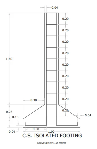
- To draw the cross section of isolated footing.
- To draw line diagram of two bedroom building.
- To draw cross section of a load bearing wall showing foundation details.
- To draw isometric view of steps.
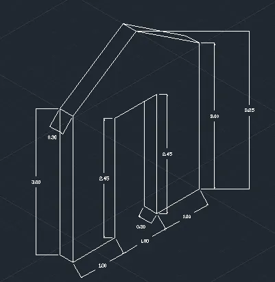
- To draw isometric view of gable wall.
INTRODUCTION:
Floor plan:
Floor plan is two dimensional drawing to scale that shows a room or building from above. It is indicates the relationshipes between rooms on one level of a structure. Architects use floor plans as tool to design buldings. Later,they are describe buildings to those involved in the construction process.
Footing:
Footing is a part of foundation which is constructed with concrete or brick work masonry & acts as a base to the floor columns & floor walls.The main function of footing is to transfer the vertical load directly to the soil.
Isometric:
Isometric snap is 3D view in which lines are inclined at 30 degree to x-axs.
Various commands & tools used are:
- Line
- Rectangle
- Trime
- Offset
- Isometric plane
- Dimension
- Text
- Copy
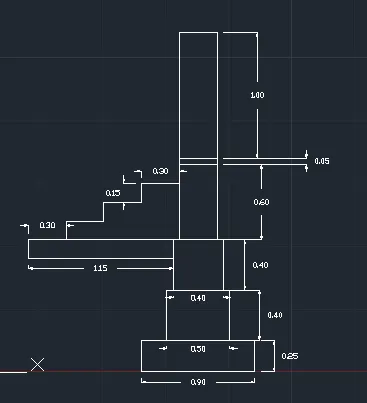
Cross section of load bearing wall over spread footing:
Procedure:
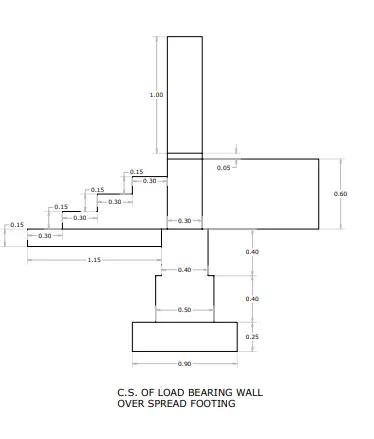
- Open autocad softwere, type QNew incommand box,press enter.
- Sleect default setting as imperial setting.
- choose the rectangle tool & specify the first point as 0,0 & press enter.
- specify the length & width of rectangle as 0.9,0.25 press enter.
- Again Choos the rectangle tool press enter.
- specify the next point as 0.20,0.25 press enter.
- specify the length & width of rectangle as @0.50,0.40 press enter.
- Again Choos the rectangle tool press enter.
- specify the next point as 0.25,0.65 press enter.
- specify the length & width of rectangle as @0.40,0.40 press enter.
- Again Choos the rectangle tool press enter.
- specify the next point as 0.30,1.05 press enter.
- specify the length & width of rectangle as @0.30,0.60 press enter.
- Again Choos the rectangle tool press enter.
- specify the next point as 0.30,1.65 press enter.
- specify the length & width of rectangle as @0.30,0.15 press enter.
- Again Choos the rectangle tool press enter.
- specify the next point as 0.30,1.7 press enter.
- specify the length & width of rectangle as @0.30,1 press enter.
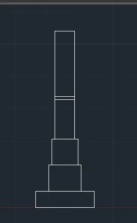
- Again Choos the rectangle tool press enter.
- specify the next point as 0.30,1.05 press enter.
- specify the length & width of rectangle as @-1.15,-0.15 press enter.
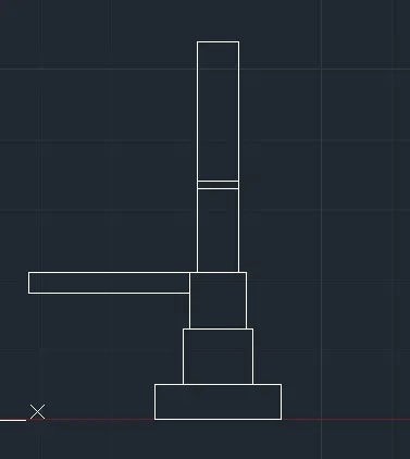
- Choose the line option in command box.
- specify the next point as 0.30,1.5 press enter.
- next point as @0.30<180 press enter.
- next point as @ 0.15<270 press enter
- next point as @ 0.30<180 press enter
- next point as @ 0.15<270 press enter
- next point as @ 0.30<180 press enter
- next point as @ 0.15<270 press enter
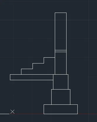
- After completion of drawing give dimension usind dimension tool.
Result
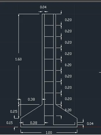
Cross section of isolated footing:
Procedure:
- Open autocad softwere, type QNew incommand box,press enter.
- Sleect default setting as imperial setting.
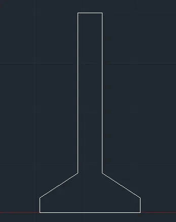
- choose the rectangle tool & specify the first point as 1,1 & press enter.
- specify the next point as @0,0.15 & press enter.
- specify the next point as @0.30,0.25 & press enter.
- specify the next point as @0,1.6 & press enter.
- specify the next point as @0.24,0 & press enter.
- specify the next point as @0,-1.6 & press enter.
- specify the next point as @0.38,-0.25 & press enter.
- specify the next point as @0,-0.15 & press enter.
- specify the next point as @-1,0 & press enter or close option in command box.
- choose the line tool specify the point 1.42,3 & press enter.
- specify the next point as @0,-1.96 & press enter.
- specify the next point as @-0.38,0 & press enter.
- specify the next point as @0,0.04 & press enter.
- Choose line tool specify the point 1.58,3 & press enter.
- specify the next point as @0,-1.96 & press enter.
- specify the next point as @0.38,0 & press enter.
- specify the next point as @0,0.004 & press enter.
- Choose the line tool specify the point1.42,1.2 & press enter.
- specify the next point as @0.16,0 & press enter.
- Choose the offset tool & type offset distance 0.2 in command box & press enter.
- Selecte the above drawing line & take eight offsets in in upward side of the line.
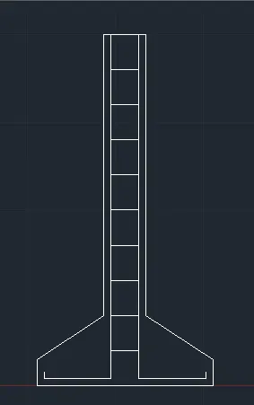
- After completion of drawing give dimension usind dimension tool.
Result
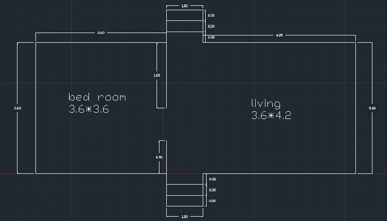
Line diagram of two-bedroom building:
Procedure:
- Open autocad softwere, type QNew incommand box,press enter.
- Sleect default setting as imperial setting.
- choose the rectangle tool & specify the first point as 1,1 & press enter.
- specify the next point as @3.60,0 & press enter.
- specify the next point as @0.-0.9 & press enter.
- specify the next point as @1,0 & press enter.
- specify the next point as @0,0.9 & press enter.
- specify the next point as @4.2,0 & press enter.
- specify the next point as @0,0.9 & press enter.
- specify the next point as @-1,0 & press enter.
- specify the next point as @0,-0.9 & press enter.
- specify the next point as @-3.6,0 & press enter.
- Click on the close option in the command box.
- Choose the line tool, specify the point 4.6,1 & press enter.
- Specify next point @0,0.90 & press enter.
- Againe choose line tool & specify the point 4.6,4.6 & press enter.
- Specify next point @0,-1.8 & press enter.
- Choose the offset tool & specify offset distance 0.3 & press enter.
- Slelect the one unit length line & take two offsets in downward direction for upward step.
- Similarly take two offsets in upward direction for the downward steps.
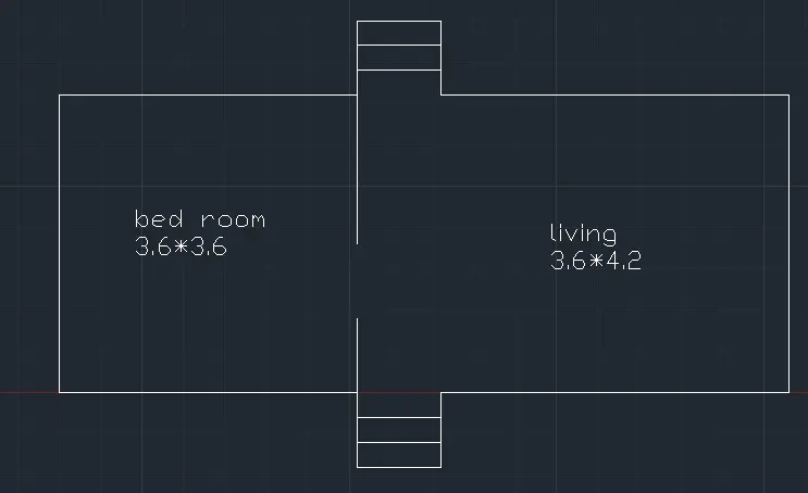
- After completion of drawing give dimension usind dimension tool.
Result
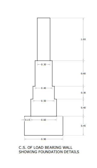
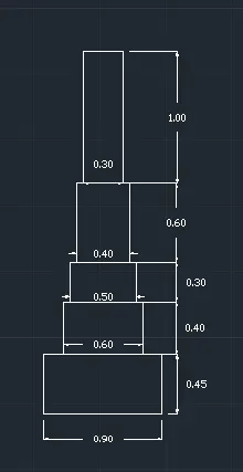
Cross section of load bearing wall showing foundation details:
Procedure:
- Open autocad softwere, type QNew incommand box,press enter.
- Sleect default setting as imperial setting.
- choose the rectangle tool & specify the first point as 0,0 & press enter.
- specify the length & width of rectangle as 0.9,0.45 press enter.
- Again Choos the rectangle tool press enter.
- specify the next point as 0.15,0.45 press enter.
- specify the length & width of rectangle as @0.60,0.40 press enter.
- Again Choos the rectangle tool press enter.
- specify the next point as 0.20,0.85 press enter.
- specify the length & width of rectangle as @0.50,0.30 press enter.
- Again Choos the rectangle tool press enter.
- specify the next point as 0.25,1.15 press enter.
- specify the length & width of rectangle as @0.4,0.60 press enter.
- Again Choos the rectangle tool press enter.
- specify the next point as 0.30,1.75 press enter.
- specify the length & width of rectangle as @0.30,1 press enter.
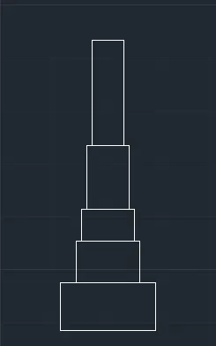
- After completion of drawing give dimension usind dimension tool.
Result
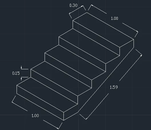
Isometric view of steps:
Procedure:
- Open autocad softwere, type QNew incommand box,press enter.
- Sleect default setting as imperial setting.
- Type the DS in command box & press enter.
- In snapn & grid tab select snap type as isometric snap & click on ok, cursor changes to isoplane left.
- Or click on isometric drafting on status bar & make it on.
- Click on the ortho made on status bar to restrict directions to 90 & 30 inclined to x axis.
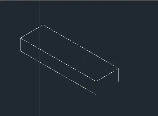
- Choose line tool & specify first point.
- Move the cursor up & type distance 0.15 & press enter.
- Position the cursor in left up, type the distance 1 in command box press enter.
- Position the cursor in downward direction , type distance 0.15 & press enter & choose the close option in command box.
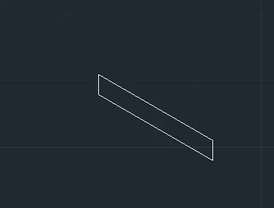
- Using F5 key change the isoplane left to isoplane top or change it by using isometric drafting setting of status bar.
- Again choose the line tool & specify the first point.
- Position the cursor in right up direction type distance 0.3 & press enter.
- Position the cursor in left up direction type distance 1 & press enter.
- Position the cursor in left down direction type distance 0.15 & press enter.
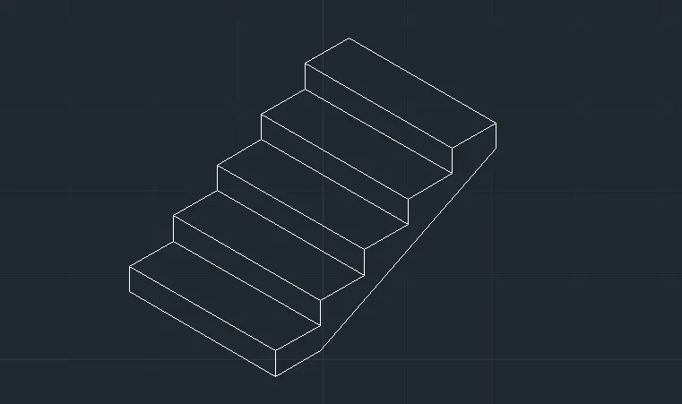
- Choose the copy tool & select the alll lines using crossing window & choose base point as corner of first step.
- Specify second point as similar corner point of next step. Respect the same procedure for three more times & create five steps.
- Using F5 key change the isoplane top to isoplane right.
- Choose the line tool & from corner point of topmost step draw line in downward direction having length of 0.15 unit.
- With the line tool draw line of length 0.3 from first corner point of first step in isoplane right & join the above two draw line using line tool.
- After completion of drawing give dimension to aligned using dimension tool.
Result
Isometric view of gable wall:
Procedure:
- Open autocad softwere, type QNew incommand box,press enter.
- Sleect default setting as imperial setting.
- Type the DS in command box & press enter.
- In snapn & grid tab select snap type as isometric snap & click on ok, cursor changes to isoplane left.
- Or click on isometric drafting on status bar & make it on.
- Click on the ortho made on status bar to restrict directions to 90 & 30 inclined to x axis.
- Choose line tool & specify first point.
- Move the cursor in right direction & type distance 1.5 & press enter.
- Position the cursor in up, type the distance 1 in command box press enter.
- Close the geometry it will create the triangle.
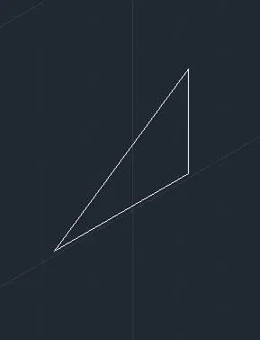
- Again choose line tool & select closed vertex of triangle as first point & move cursor in downward direction & type distance 3 & press enter.
- Position the cursor in right up type distance 1 & press enter.
- Position the cursor in upward type distance 2.42 & press enter.
- Position the cursor in right direction type 1 & press enter.
- Position the cursor in downward direction type distance 2.42 & press enter.
- Position the cursor in right direction type distance 1 & press enter.
- Move the cursor in upward direction type distance 3 & press enter.
- Now, close the diagram by joining the end point of last line with the topmost vertex of triangle & press enter.
- Now erase the 1.5 & 1 unit lines using erase tool.

- Change isoplane right to top by using status bar.
- Now copy the joined line at distance of 0.3 from the same line & join the end point of these lines by 0.3 unit lines.
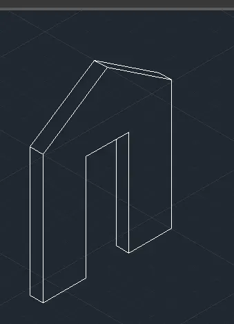
- After completion of drawing give dimension to aligned using dimension tool.
Result