Creation of geometries by Coordinate system methods using AutoCad
CREATE OF GEOMETRICS BY COORDINATE SYSTEM METHODS USING AUTOCAD
Jagadeep.M.M
AIM:
- Create the geometries from P1 to P2 using all the coordinates system methods.
- Create the geometries from P4 to P10 using any one coordinates systeem methods.
- Draw the profile and the trusses using any coordinate system methods.
Introduction:
Coordinate system:
There are 3 coordinate systems
- Absolute coordinate system:Plotting point with respect to origin.
- Relative coordinate system:Plotting next point with respect to previous point.
Relative rectangular coordinate system
Relative polar coordinate system
3. Direct distance entry system:Plotting next point by positioning the cursor in desired direction & mentioning the distance directly.
Creating P1 drawing using all coordinate system method:
Creating P1 drawing using absolute coordinate system method:
Procedure:
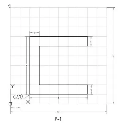
- Type L in command box or use line tool from the tool bar or menu bar or any other convenient method.
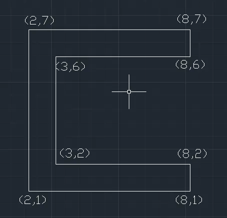
- Specify the coordinates of first point (2,1)in the command box press enter botton.
- Then specify next point (8,1)in the command box press enter botton.
- Then type next point (8,2)in the command box press enter botton.
- Then type next point (3,2)in the command box press enter botton.
- Then type next point (3,6)in the command box press enter botton.
- Then type next point (8,6)in the command box press enter botton.
- Then type next point (8,7)in the command box press enter botton.
- Then type next point (2,7)in the command box press enter botton.
- The close the drawing using close option n command box or type the coordinates of first point (2,1) & press enter.
Output
Creating P1 drawing using relative rectangular coordinate system method:
Procedure:
- Type L in command box or use line tool from the tool bar or menu bar or any other convenient method.
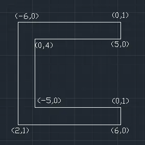
- Type the relative rectangular coordinates (2,1) in command box & press enter.
- Then specify next point as @6,0 in command box & press enter.
- Then next point as @0,1 in command box & press enter.
- Then next point as @-5,0 in command box & press enter.
- Then next point as @0,4 in command box & press enter.
- Then next point as @5,0 in command box & press enter.
- Then next point as @0,1 in command box & press enter.
- Then next point as @-6,0 in command box & press enter botton or click on close option in command box.
Creating P1 drawing using relative polar coordinate system method:
Procedure
- Type L in command box or use line tool from the tool bar or menu bar or any other convenient method.
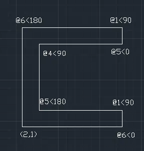
- Type the relative polar coordinates (2,1) in command box & press enter.
- Then specify next point as @6<0 in command box & press enter.
- Then next point as @1<90 in command box & press enter.
- Then next point as @5<180 in command box & press enter.
- Then next point as @4<90 in command box & press enter.
- Then next point as @5<0 in command box & press enter.
- Then next point as @1<90 in command box & press enter.
- Then next point as @6<180in command box & press enter botton or click on close option in command box.
Output
Creating P1 drawing using direct distance entry method:
Procedure
- Type L in command box or use line tool from the tool bar or menu bar or any other convenient method.
- Type the first point by absolute coordinate method by typing 2,1& press the enter button.
- Switch on the ortho mode in status bar.
- position the cursor rightward in positive X direction & type distance 6 in the command box & press enter.
- Then position the cursor upward in positive Y direction & type distance 1 in the command box & press enter.
- Then position the cursor leftward in negative X direction & type distance 5 in the command box & press enter.
- Then position the cursor upward in positive Y direction & type distance 4 in the command box & press enter.
- Then position the cursor rightward in positive X direction & type distance 5 in the command box & press enter.
- Then position the cursor uptward in positive Y direction & type distance 1 in the command box & press enter.
- Then position the cursor leftward in negative X direction & type distance 6 in the command box & press enter.
- Then close option in command box or position the cursor downward in negative Y direction & type distance 6 in the command box & press enter.
Output
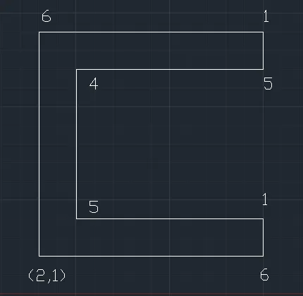
Creating P1 drawing using all coordinate system method:
Creating P2 drawing using absolute coordinate system method:
Procedure:
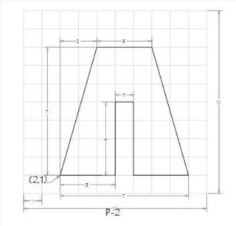
- Type L in command box or use line tool from the tool bar or menu bar or any other convenient method.
- Specify the coordinates of first point (2,1)in the command box press enter botton.
- Then type next point (4,8)in the command box press enter botton.
- Then type next point (7,8)in the command box press enter botton.
- Then type next point (9,1)in the command box press enter botton.
- Then type next point (6,1)in the command box press enter botton.
- Then type next point (6,5)in the command box press enter botton.
- Then type next point (5,5)in the command box press enter botton.
- Then type next point (5,1)in the command box press enter botton.
- The close the drawing using close option n command box or type the coordinates of first point (2,1) & press enter.
Output
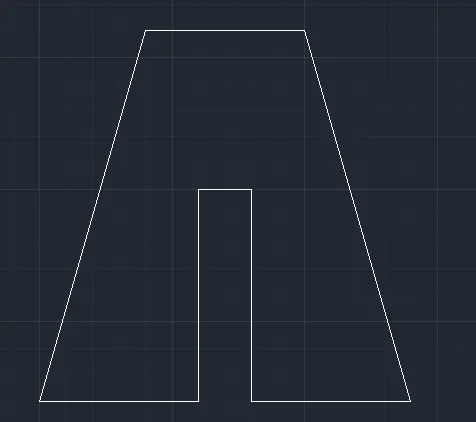
Creating P2 drawing using relative rectangular coordinate system method:
Procedure:
- Type L in command box or use line tool from the tool bar or menu bar or any other convenient method.
- Type the relative rectangular coordinates (2,1) in command box & press enter.
- Then specify next point as @2,7 in command box & press enter.
- Then next point as @3,0 in command box & press enter.
- Then next point as @2,-7 in command box & press enter.
- Then next point as @-3,0 in command box & press enter.
- Then next point as @0,4 in command box & press enter.
- Then next point as @-1,0 in command box & press enter.
- Then next point as @0,-4 in command box & press enter.
- Then next point as @-3,0 in command box & press enter botton or click on close option in command box.
Output
Creating P2 drawing using relative polar coordinate system method:
Procedure
- Type L in command box or use line tool from the tool bar or menu bar or any other convenient method.
- Type the relative polar coordinates (2,1) in command box & press enter.
- Then specify next point as @7.280<74 in command box & press enter.
- Then next point as @3<0 in command box & press enter.
- Then next point as @7.280<286 in command box & press enter.
- Then next point as @3<180 in command box & press enter.
- Then next point as @4<90 in command box & press enter.
- Then next point as @1<180 in command box & press enter.
- Then next point as @4<270 in command box & press enter.
- Then next point as @3<180 in command box & press enter botton or click on close option in command box.
Output
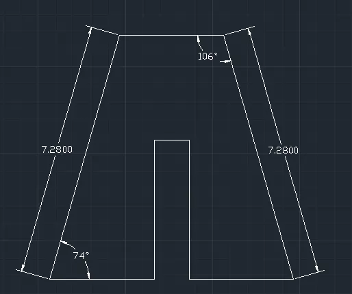
Creating P2 drawing using direct distance entry method:
Procedure
- Type L in command box or use line tool from the tool bar or menu bar or any other convenient method.
- Type the first point by absolute coordinate method by typing 2,1& press the enter button.
- Switch on the ortho mode in status bar.
- position the cursor rightward in positive X direction & type distance 3 in the command box & press enter.
- Then position the cursor upward in positive Y direction & type distance 4 in the command box & press enter.
- Then position the cursor rightward in positivetive X direction & type distance 1 in the command box & press enter.
- Then position the cursor downward in negative Y direction & type distance 4 in the command box & press enter.
- Then position the cursor rightward in positive X direction & type distance 3 in the command box & press enter.
- Then position the cursor uptward in positive Y direction & type distance in the command box & press enter.
- move the cursor at angle of 106 & type the distance 7.280 & press enter.
- Then the position the cursor leftward in negative X direction &ntype the distance 3 & press enter
- Then close option in command & close the drawing.
Output
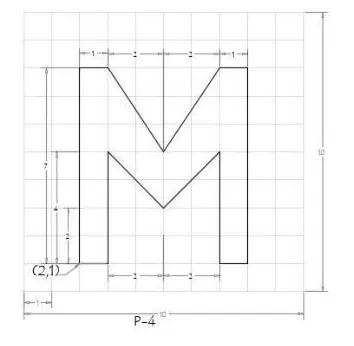
Creating P4 drawing using absolute coordinate system method:
Procedure:
- Type L in command box or use line tool from the tool bar or menu bar or any other convenient method.
- Specify the coordinates of first point (2,1)in the command box press enter botton.
- Then specify next point (3,1)in the command box press enter botton.
- Then type next point (3,5)in the command box press enter botton.
- Then type next point (5,3)in the command box press enter botton.
- Then type next point (7,5)in the command box press enter botton.
- Then type next point (7,1)in the command box press enter botton.
- Then type next point (8,1)in the command box press enter botton.
- Then type next point (8,8)in the command box press enter botton.
- Then type next point (7,8)in the command box press enter botton.
- Then type next point (3,8)in the command box press enter botton.
- Then type next point (2,8)in the command box press enter botton.
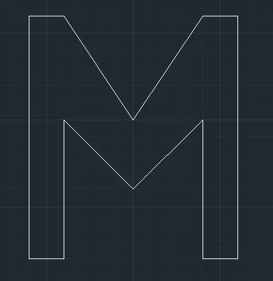
- The close the drawing using close option n command box or type the coordinates of first point (2,1) & press enter
Output
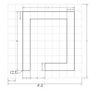
Creating P5 drawing using absolute coordinate system method:
Procedure:
- Type L in command box or use line tool from the tool bar or menu bar or any other convenient method.
- Specify the coordinates of first point (2,1)in the command box press enter botton.
- Then specify next point (3,1)in the command box press enter botton.
- Then type next point (3,8)in the command box press enter botton.
- Then type next point (8,8)in the command box press enter botton.
- Then type next point (8,2)in the command box press enter botton.
- Then type next point (5,2)in the command box press enter botton.
- Then type next point (5,1)in the command box press enter botton.
- Then type next point (9,1)in the command box press enter botton.
- Then type next point (9,9)in the command box press enter botton.
- Then type next point (2,9)in the command box press enter botton.
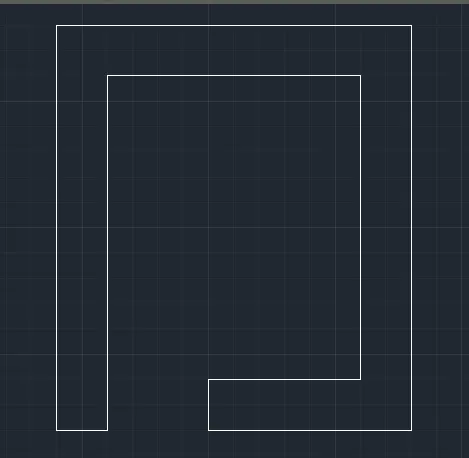
- The close the drawing using close option n command box or type the coordinates of first point (2,1) & press enter
Output
Creating P7 drawing using absolute coordinate system method:
Procedure:
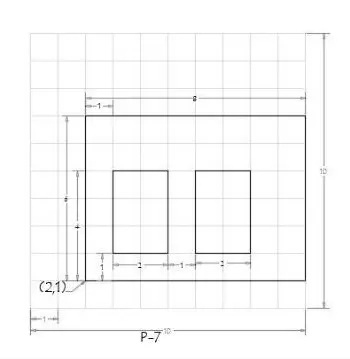
- Type L in command box or use line tool from the tool bar or menu bar or any other convenient method.
- Specify the coordinates of first point (2,1)in the command box press enter botton.
- Then specify next point (10,1)in the command box press enter botton.
- Then type next point (10,7)in the command box press enter botton.
- Then type next point (2,2)in the command box press enter botton.
- Close the option in the command box.
- Again choose the line tool & specify or type the point(3,2)in the command box & press the enter.
- Then specify next point (5,2)in the command box press enter botton.
- Then type next point (5,5)in the command box press enter botton.
- Then type next point (3,5)in the command box press enter botton.
- Close the option in the command box.
- Again choose the line tool & specify or type the point(6,2)in the command box & press the enter.
- Then specify next point (8,2)in the command box press enter botton.
- Then type next point (8,5)in the command box press enter botton.
- Then type next point (6,5)in the command box press enter botton.
- Close the option in the command box.
Output
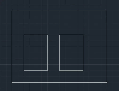
Creating P8 drawing using absolute coordinate system method:
Procedure:
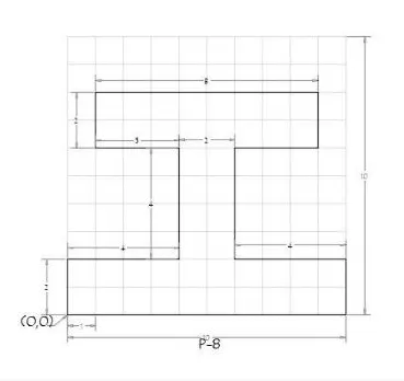
- Type L in command box or use line tool from the tool bar or menu bar or any other convenient method.
- Specify the coordinates of first point (0,0)in the command box press enter botton.
- Then specify next point (10,0)in the command box press enter botton.
- Then type next point (10,2)in the command box press enter botton.
- Then type next point (6,2)in the command box press enter botton.
- Then type next point (6,6)in the command box press enter botton.
- Then type next point (9,6)in the command box press enter botton.
- Then type next point (9,8)in the command box press enter botton.
- Then type next point (1,8)in the command box press enter botton.
- Then type next point (1,6)in the command box press enter botton.
- Then type next point (4,6)in the command box press enter botton.
- Then type next point (4,2)in the command box press enter botton.
- Then type next point (0,2)in the command box press enter botton.
- The close the drawing using close option n command box or type the coordinates of first point (0,0) & press enter
Output
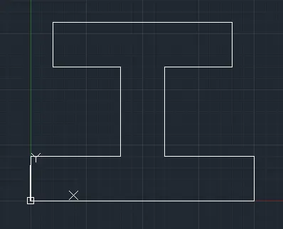
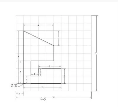
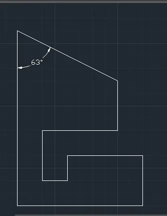
Creating P9 drawing using relative polar coordinate system method:
Procedure
- Type L in command box or use line tool from the tool bar or menu bar or any other convenient method.
- Type the relative polar coordinates (1,1) in command box & press enter.
- Then specify next point as @5<0 in command box & press enter.
- Then next point as @2<90 in command box & press enter.
- Then next point as @3<180 in command box & press enter.
- Then next point as @1<270 in command box & press enter.
- Then next point as @1<180 in command box & press enter.
- Then next point as @2<90 in command box & press enter.
- Then next point as @3<0 in command box & press enter.
- Then next point as @2<90 in command box & press enter.
- Then next point as @4.4721<153 in command box & press enter.
- Then next point as @7<270 in command box & press enter botton or click on close option in command box.
Output
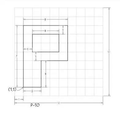
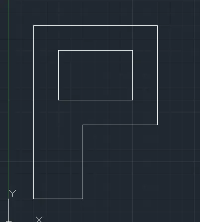
Creating P10 drawing using relative polar coordinate system method:
Procedure
- Type L in command box or use line tool from the tool bar or menu bar or any other convenient method.
- Type the relative polar coordinates (1,1) in command box & press enter.
- Then specify next point as @2<0 in command box & press enter.
- Then next point as @3<90 in command box & press enter.
- Then next point as @3<0 in command box & press enter.
- Then next point as @4<90 in command box & press enter.
- Then next point as @5<180 in command box & press enter.
- Then next point as @@7<270 in command box & press enter or click om close option in command.
- Again choose the line tool & specify or type the point(2,5)in the command box & press the enter.
- Then next point as @3<0 in command box & press enter.
- Then next point as @2<90 in command box & press enter.
- Then next point as @3<180 in command box & press enter.
- Then next point as @2<270 in command box & press enter botton or click on close option in command box.
Output
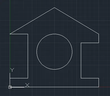
Drawing the profile of wood using absolute coordinate system method:
Procedure:
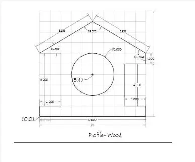
- Type L in command box or use line tool from the tool bar or menu bar or any other convenient method.
- Specify the coordinates of first point (0,0)in the command box press enter botton.
- Then specify next point (10,0)in the command box press enter botton.
- Then type next point (10,1)in the command box press enter botton.
- Then type next point (8,1)in the command box press enter botton.
- Then type next point (8,5)in the command box press enter botton.
- Then type next point (10,5)in the command box press enter botton.
- Then type next point (10,6)in the command box press enter botton.
- Then type next point (5,9)in the command box press enter botton.
- Then type next point (0,6)in the command box press enter botton.
- Then type next point (2,6)in the command box press enter botton.
- Then type next point (2,1)in the command box press enter botton.
- Then type next point (0,1)in the command box press enter botton.
- Then type next point as (0,0) in command box & press enter botton or click on close option in command box.
- Type C or Circle in the command box & press enter.
- Then specify center point coordinate of circle (5,4) in command box & press enter.
- Then specify radius of circle as 2 in the command box & press enter.
Output
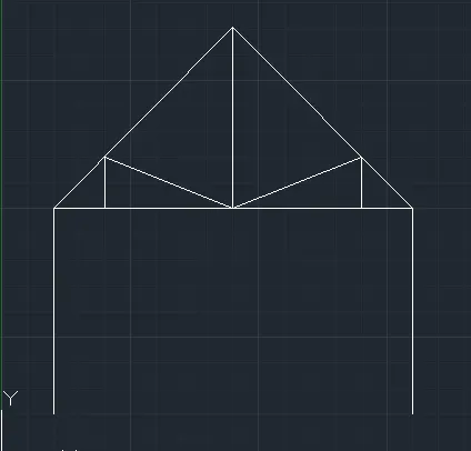
Drawing the Queen post truss using absolute coordinate system method:
Procedure:
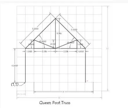
- Type L in command box or use line tool from the tool bar or menu bar or any other convenient method.
- Specify the coordinates of first point (1,1)in the command box press enter botton.
- Then specify next point (1,5)in the command box press enter botton.
- Then type next point (8,5)in the command box press enter botton.
- Then type next point (8,1)in the command box press enter botton.
- Close the option in the command box.
- Again choose the line tool & specify or type the point(2,5)in the command box & press the enter.
- Then type next point (2,6)in the command box press enter botton.
- Then type next point (4.5,5)in the command box press enter botton.
- Then type next point (7,6)in the command box press enter botton.
- Then type next point (7,5)in the command box press enter botton.
- Close the option in the command box.
- Again choose the line tool & specify or type the point(4.5,5)in the command box & press the enter.
- Then type next point (4.5,8.536)in the command box press enter botton.
- Close the option in the command box.
- Again choose the line tool & specify or type the point(1,5)in the command box & press the enter.
- Then type next point (4.5,8.536)in the command box press enter botton.
- Then type next point as (8,5) in command box & press enter botton or click on close option in command box.
Output
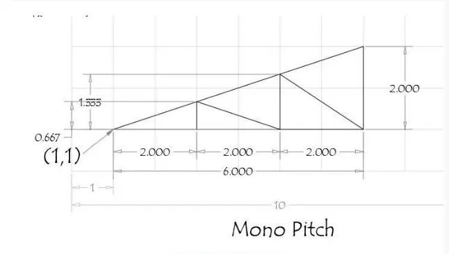
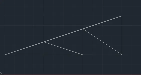
Drawing the Mono pitch using absolute coordinate system method:
Procedure:
- Type L in command box or use line tool from the tool bar or menu bar or any other convenient method.
- Specify the coordinates of first point (1,1)in the command box press enter botton.
- Then specify next point (7,1)in the command box press enter botton.
- Then type next point (7,3)in the command box press enter botton.
- Close the option in the command box.
- Again choose the line tool & specify or type the point(3,1)in the command box & press the enter.
- Then specify next point (3,1.667)in the command box press enter botton.
- Then type next point (5,1)in the command box press enter botton.
- Then type next point (5,2.333)in the command box press enter botton.
- Then type the next point (7,1) in command box & press enter.
Output
Result:
- P1 &P2 are drawn successfully using all the coordinate system method.
- P4 to P10 are drawn succesfully using one of the coordinate system method mensioned above.
- Profile of wood, Queen post truss & mono pitch is drawn by using one coordinate method.
- By following the procedure as mensioned above the output are obtained as shown above.