Week 1 Challenge
1)
1.
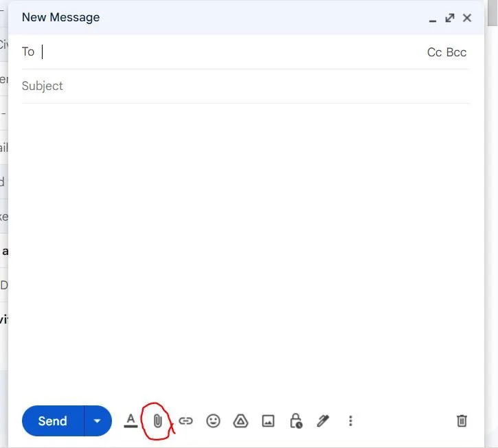
- To upload a staad file via mail, first save the required file in .std format.
- go to mail, compose mail, select 'attach file' option , and select the required file from the PC and send
2.
- With STAAD pro you can model comprehensive steel plate-work, including gusset plates and chute work.
- Produce structural design documentation – You can create the structural design documents along with the necessary plans & elevations being used to convey the design purpose.
- It can be used to design steel, concrete structures, design steel and reinforced concrete buildings in accordance with specific country codes
- It can perform linear elastic (static and dynamic) as well as nonlinear dynamic analysis.
- the different materials like steel , aluminium , concrete can be defined in staad. pro.
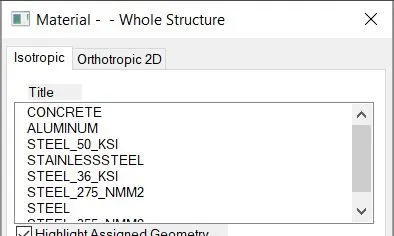
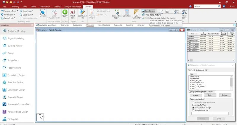
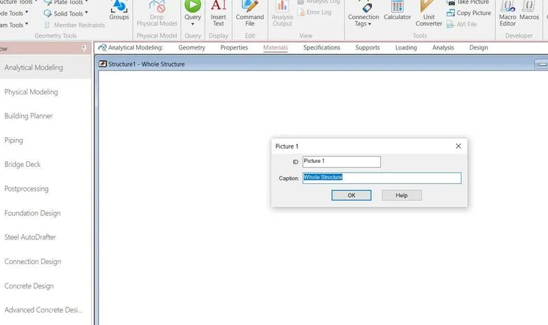
3. To capture images in Staad. Pro. go to utilities, ther eis an option to 'take a picture'. select that option and save the file.
4.
- STAAD.Pro. physical modeler interface
- traditional STAAD.Pro. analytical modelling interface
- using the command file
The physical model is used to draw structural elements as they are physically constructed. The program will then decompose this into an analytical modeling which is passed to the STAAD.Pro analysis and design engine when you run your model.
The analytical model is a finite element model of the structure which is typically processed directly by the analysis and design engine.
The command input file is a text file which contains the data for your structural model. This file consists of simple English language-like commands. This file is created for you behind the scenes for you when you model your structure using either the physical modeler interface or the analytical model interface.
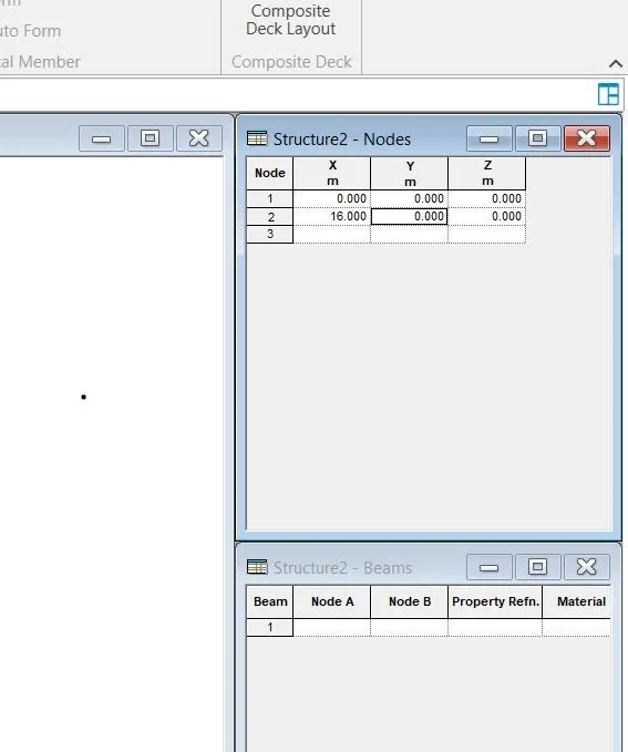
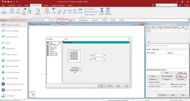
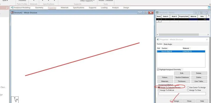
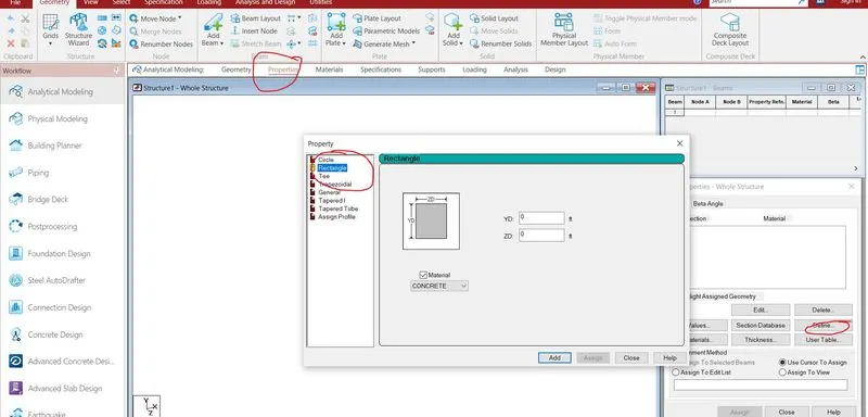
5. The following is the procedure to be followed to assign properties in STAAD.Pro.
go to properties tab, define, and select the shape and material required
2)
1. Any 6 design parameters are :- depth, clear cover ,FC- concrete yeild stress, FyMain -Yield Stress for main reinforcing steel., MaxMain- max main reinforcement bar szie , MinSec- Minimum secondary reinforcement bar size
2.
- arrow cursor
- text pointer
- hand cursor
- hourglass
- help pointer
- object resizing cursor
- pencil cursor
- precision pointer
- white cross cursor
- move cursor
- zoom in /out cursor
- grab cursor
- scroll cursor
- unavailable pointer
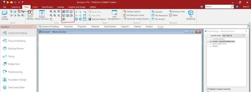
3. go to view tab and there you will see different rectangular boxes which represent a different view of the drawing
the screenshots below represent the different views
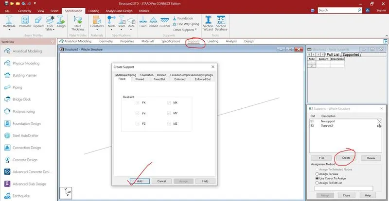
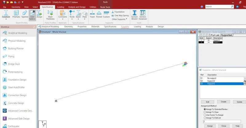
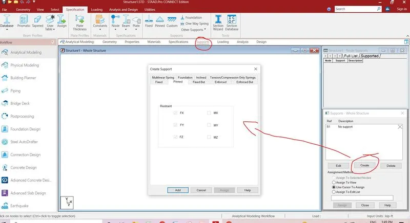
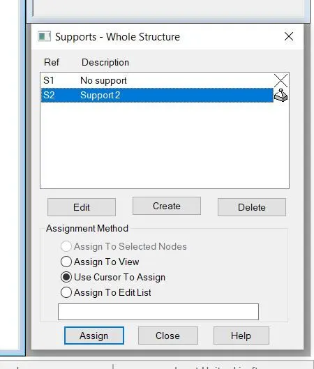
4. to define a simply supported condition in staad pro. draw a beam . then go to supports option and select pinned option and add. then after selecting the support use the options below to assign the support.
5. Five topics to be included in creating a design basis report are :-
- job info
- structural layouts
- loads and combinations
- analysis and design methodology
- failed members table
- appendix
3)
1. The different types of structural systems availaale in staad pro. are nodes, beams ,columns ,slabs etc .
2. STAAD.Pro uses two types of coordinate systems to define the structure geometry and loading patterns. The GLOBAL coordinate system is an arbitrary coordinate system in space which is utilized to specify the overall geometry & loading pattern of the structure. A LOCAL coordinate system is associated with each member (or element) and is utilized in MEMBER END FORCE output or local load specification.
3. DBR is DEsign Basis Report.It is used to specify and compile the data required for analysis and design of structural elemnets of the project. DR clearly depicts the assumptions and specifications that are being used to develop the construction documents for a project. It will also help avoid "scope, creep" that cab dereail the project schedule and lead to budget overruns.
The steps for creating a DR are as follows :-
- Perform an analysis/design on the job for which you want to create a report.
- Select the Report Setup for Printing tool on the Home ribbon tab.The Report Setup dialog opens.
- Select the job for which you want to set up a report.The available report items for the selected job are displayed in the Available list.
- Use the arrow buttons or double click items to have them included in the Selected list.
- (Optional) Change the report look using the Header and Logo tab.
- Click the OK button.
4. the different types of analysis available is staad are as follows
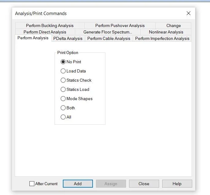
Buckling analysis:- buckling is a mathematical instability, leading to a failure mode before reaching the material strength. Mathematically, this point is also defined as a point of Bifurcation to the solution of the Static equilibrium.
Types of Buckling:
- Flexural Buckling
- Torsional Buckling
- Lateral Torsional Buckling
- Flexural Torsional Buckling
- Local Buckling
Pushover analysis :- Pushover analysis is a static, nonlinear procedure using simplified nonlinear technique to estimate seismic structural deformations. It is an incremental static analysis used to determine the force-displacement relationship, or the capacity curve, for a structure or structural element.
Direct analysis :-The beauty of the Direct Analysis feature in Staad is that, program performs the iterations for both the geometric and material nonlinearity to capture the real effect. Effect of the actual geometric non-linearity is determined by the P-Delta analysis and the material inelasticity by iteration of τb value.
The AISC 360-05 Chapter-C specifies that the stability shall be provided for the structure as a whole and for each of its elements.That means the stability needs to be maintained for the individual members, connections, joints and other building elements as well as the structural system as a whole.The code recommends using any method that ensures the stability of the structure as a whole and for individual building elements and meets with all the following requirements are permitted.
- Flexural, shear and axial member deformations and all other deformations that contribute to displacements of the structure.
- Second-order effects (both P-∆ and P- Ϩ effects)
- Initial geometric imperfections
- Stiffness reduction due to inelasticity
- Uncertainty in stiffness and strength
AISC suggests adopting the Direct Analysis Method (DAM) which satisfies all the aforementioned conditions.
Generate floor spectrum :- Floor Response Spectrum constitutes the input data for the equipment analysis that might be sitting on a framed structure – for example, a piece of machinery sitting on the floor of a building. If the equipment were supported on the ground level, the ground acceleration spectra should have been used to analyse the equipment. However, if the equipment was to rest on any particular floor of a building, the analysis of the equipment would need the response spectra data for that floor, which would be considered as a base excitation data for that equipment. This spectra data is also known as the Floor Response Spectra or the In-structure Response Spectra. This data needs to be provided by the structural engineer.
Non linear analysis :-Non-linear analysis can be used when all of the members, elements and support springs are linear except for cables and/or preloaded truss members. This analysis is based on applying the load in steps with equilibrium iterations to converge at each step. In Staad Pro software, the iteration continues at each step until the change in deformations is small before proceeding to the next step.
Cable analysis :-Used to assign the commands required to perform a non-linear cable analysis on the model. This requires the presence of non-linear cables in the structure.
Imperfection analysis :- Perform Imperfection Analysis tab Used to instruct STAAD.Pro to perform an imperfection analysis, which will reflect the secondary effects only if the camber and/or drift is specified in a using the Define Imperfection command. For combination of load cases, with imperfection, use the Repeat Load specification rather than the Load Combination.
P delta analysis :- A regular STAAD.Pro P-Delta Analysis performs a first order linear analysis and obtains a set of joint forces from member/plates based on the large P-Delta effect. These forces are added to the original load vector. A second analysis is then performed on this updated load vector .
The following options are available in STAAD.Pro when performing a P-Delta analysis:
-
P-Delta analysis with Small & Large Delta effects or Large Delta effects only. With this option the global forces are adjusted with every iteration
- -Delta analysis including stress stiffening effect of the KG matrix. With this option the global stiffness is adjusted with every item
5. Fixed supports are restrained in all six degrees of freedom (TX, TY, TZ, RX, RY, and RZ)
The Fixed But support condition is used to allow the user to define which degrees of freedom of a node are free and which are fixed. In case you want to add a horizontal restraint which does not give vertical restraint, you can define FIXED BUT FY MX MY MZ
PRCATICAL
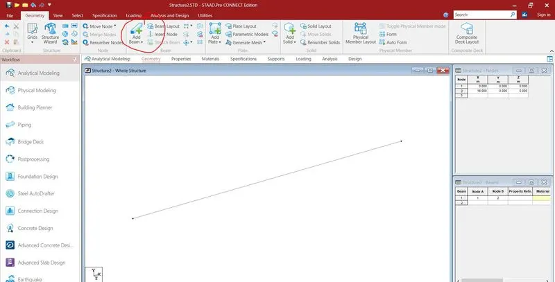
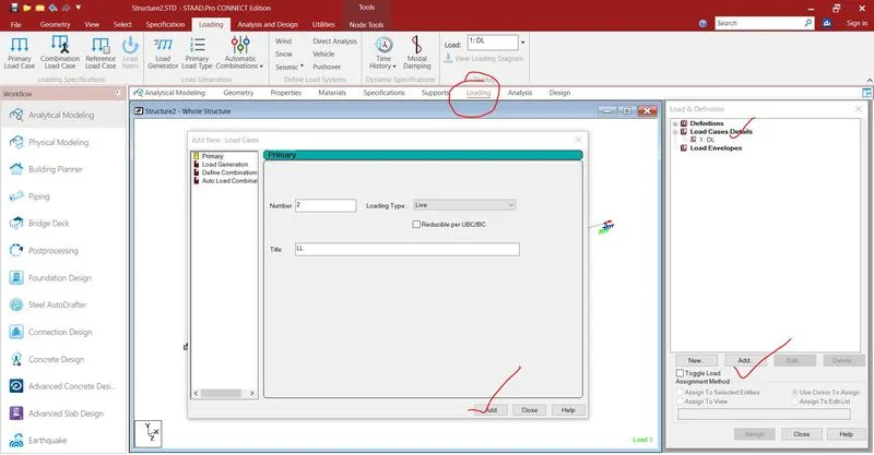
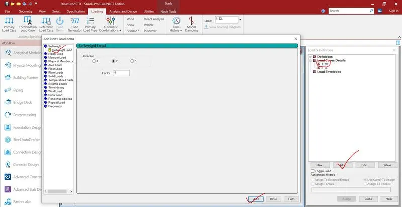
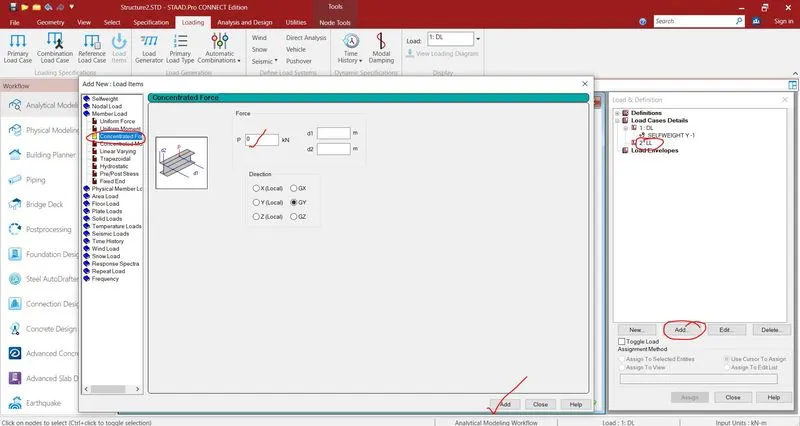
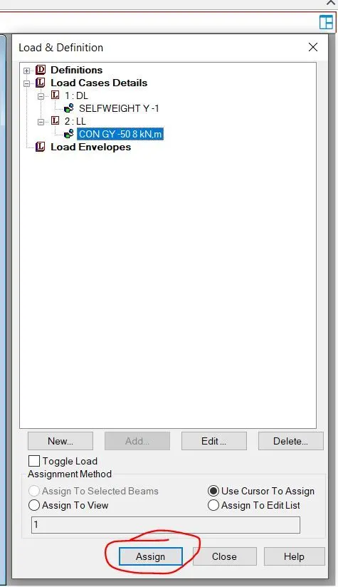
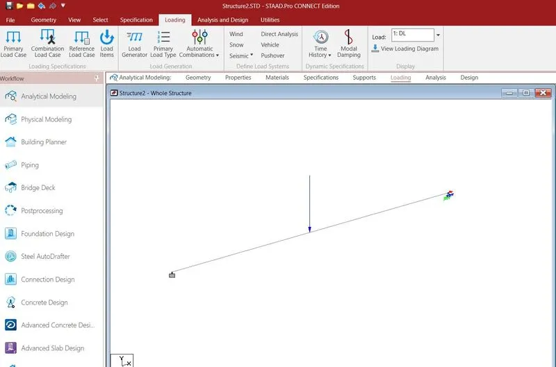
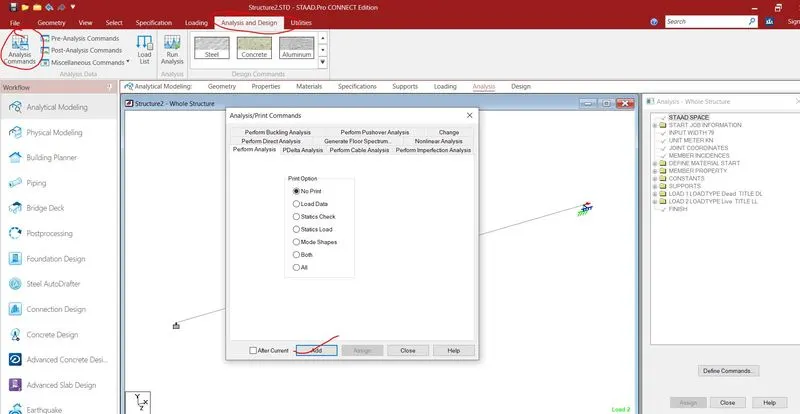
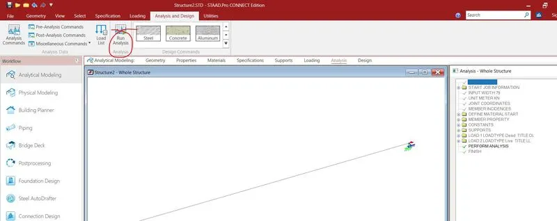
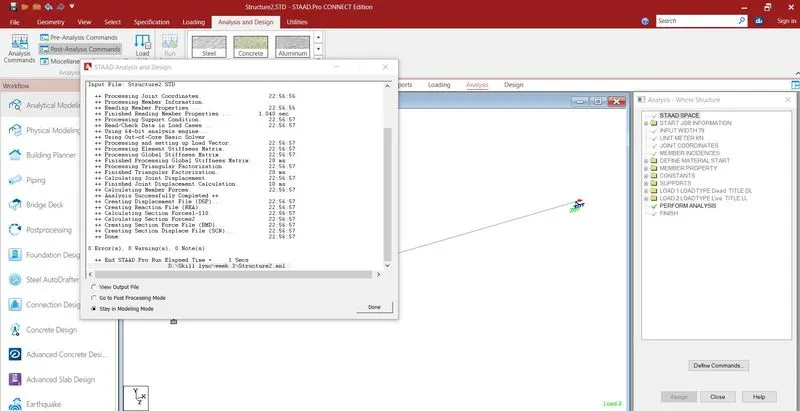
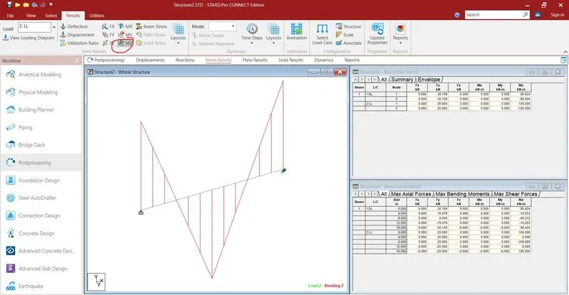
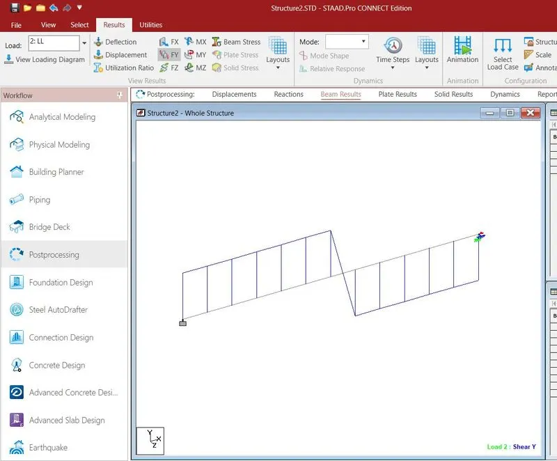
The procedure is as shown in the below screenshots :-