Week 1 Challenge
Q1]
AIM: -
1.Write the steps involved to upload a .std file through web mail
2. Name the different materials that can be designed using STAAD Pro.
3. Is it possible to capture images in STAAD Pro? If yes how?
4. Name the three ways by which you can create a model.
5. Write the steps followed to assign properties in a model.
PROCEDURE:
(1)
Go to your mail.
Compose your mail.
Click on Attach to upload the required file.
Browse your file from where the file is stored.
Attach the file and click onn submit.
(2)
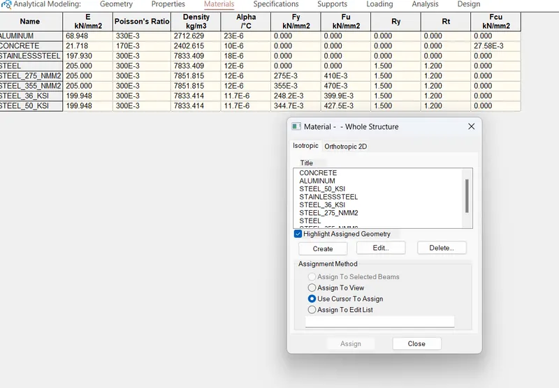
STAAD.Pro includes a set of predefined materials for Concrete, Aluminium, Timber, Steel, Stainless steel and Composite Sections.
Select the Materials page in the Analytical Modelling page control bar.
The Material - Whole Structure dialog and the Materials table open.
(3)
Yes, it is possible to capture images in STAAD Pro.
Click on UTILITIES TAB
Go to Tools Pallette
Select Take Picture option.

(4)
The three ways by which you can create a model:
a). Physical modelling Method
b). Analytical Model Method
c). Building
(5)
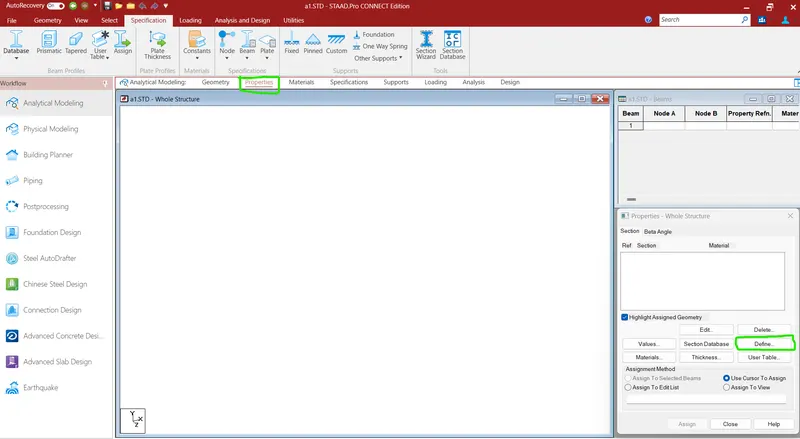
- Add the profile you want to use from the Section Database.
- Select the member property in the Properties dialog.
- Use the cursor to click on members with this property.
RESULT: -
1. Explained how to upload a .std file through web mail.
2. Mentioned the different materials that can be designed using STAAD Pro.
3. Explained how to capture images in STAAD Pro.
4. Mentioned the three ways by which we can create a model.
5. Eplained the steps to follow to assign properties in a model.
Q2]
AIM: -
1. Name any six design parameter involved in RCC design.
2. What are the different cursor types available in STAAD Pro?
3. How will you generate different views for a model? State the steps involved.
4. Explain the procedure to define a “Simply Supported” condition in STAAD Pro
5. Name any five topics that you will include while creating DBR.
6. Describe the term “Multi material design” of STAAD Pro.
PROCEDURE: -
(i)
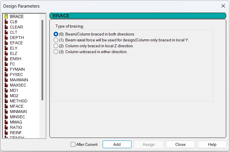
CLB - Clear cover for bottom Reinforcement
CLT - Clear cover for Top Reinforcement
FC - Compressive Strength of Concrete
FYMAIN - Yield Strength of Main Reinforcement
RATIO - Maximum % of Longitudinal Reinforcement allowed
SPSMAIN - Spacing between Main Reinforcement bars.
(ii)
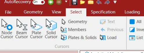
Node Cursor
Beam Cursor
Plate Cursor
Solid Cursor
(iii)
Click on VIEW TAB
Go to Tools Pallette
Choose the icon for:
Isometric View, Top view, Bottom view, Left view, Front view, Right view, and Back view.

(iv)
In the Analytical Modelling space, Click on Geometry
Create two nodes using the Grid / Coordinates option.
The two nodes denote the end of beams.
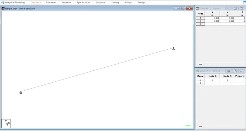
In the Analytical Modelling space, Click on Supports
Select the nodes using Nodes Cursor and go to Supports
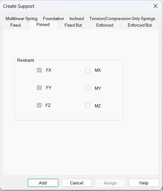
Create Pinned supports for both nodes to make it act like SS beam.
(v)
Structural Layout
Loads and Combinations
Analysis methods
Framing Plans
Load calcultions
Design methodolgy.
(vi)
The combination of different materials can be used to improve components in terms of various requirements.
STAAD. Pro has in-built options and codes to design different material like steel, concrete, Aluminium and Timber
thats why it is reffered as "Multi-Material" design.
RESULT: -
(i). Mentioned six design parameter involved in RCC design.
(ii). Provided List of different Cursors.
(iii). Explained how to generate different views for a model.
(iv). Explained the procedure to define a “Simply Supported” condition in STAAD Pro
(v). Mentioned five topics that we will include while creating DBR.
(vi). Described the term “Multi material design” of STAAD Pro.
Q3]
AIM: -
1. Name the structure systems in STAAD Pro? Explain each system?
2. Explain the coordinate system adopted in STAAD Pro software.
3. Elaborate DBR and its uses
4. Explain the different types of analysis options in STAAD pro.
5. Explain the difference between Fixed and Fixed But condition.
PROCEDURE: -
(i)
A structure can be defined as an assemblage of elements.
STAAD.Pro is capable of analyzing and designing structures consisting of frame, plate/shell, and solid elements.
a) SPACE
A3D framed structure with loads applied in any plane. This structure type is the most general.
b) PLANE
This structure type is bound by a global X-Y coordinate system with loads in the same plane.
- c) TRUSS
- This structure type consists of truss members which can have only axial member forces and no bending in the members.
- d) FLOOR
- A 2D or 3D structure having no horizontal movement of the structure.
- The floor framing of a building is an ideal example of a this type of structure.
- Columns can also be modeled with the floor in a Floor structure as long as the structure has no horizontal loading.
- If there is any horizontal load, it must be analyzed as a Space structure.
(ii)
Co-ordinate Systems
a) Global Co-ordinate System
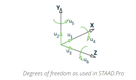
This coordinate system is a rectangular coordinate system (X, Y, Z) which follows the orthogonal "right hand" rule.
This coordinate system may be used to define the joint locations and loading directions.
The translational degrees of freedom are denoted by u1, u2, & u3 and the rotational degrees of freedom are denoted by u4, u5, & u6.
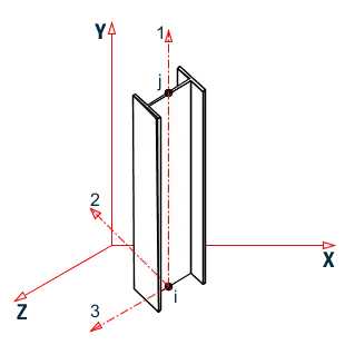
b) Local Co-ordinate System
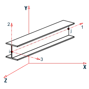
Each member or surface has its own local Cartesian coordinate system which is also oriented using the "right hand" rule.
The longitudinal axis of a member is the first axis, with the positive axis taken from the i to the j ends (i.e, Ni and Nj).
The second axis is the oriented such that the 1-2 plane is then parallel to the global Y axis.
The third axis is then normal to the first and second local axes as defined by the right hand rule.
The local 2 and 3 axes coincide with the two principle moments of inertia of the cross-section.
In the special case of a vertical member (where the local 1 axis is parallel to the global Y axis; i.e., a column), the local 3 axis is then made parallel to the global Z axis and the 2 axis is oriented respectively.
 |
 |
| (A) | (B) |
(iii)
DBR
The purpose of this document is to compile data required for analysis, design and detailing of all structural steel and RCC elements viz - Foundation, Shear walls, Beams, Columns and Slabs.
It is intended to develop a strucural scheme such that the proposed structure is able to satisfy architectural and service requirements and also meet durability, longevity and aesthetic criterias.
It depicts the assumptions and specifications that are being used to develop the documents for a project.
It will also cost help avoid the "Scope Creep" that can affect the project schedule and budget.
(iv)
Types of Analysis options STAAD: -
- Linear Static Analysis
- Second order Analysis (P -△)
- Non-Linear Analysis
- Member imperfection Analysis
- Pushover analysis (Deformation)
(v)
FIXED vs FIXED BUT
When the FIXED support is specified, for those degrees of freedom which are to be treated as fully restrained, STAAD assumes the displacements to be known quantities whose value is zero. Hence, those degrees of freedom are not considered for the stiffness matrix, and their value is not calculated.
For the FIXED BUT support type, if any degrees of freedom are assigned a spring using the KFX thru KMZ terms, those are treated as unknowns and their displacements are calculated.
RESULT: -
1. Explained the structure systems in STAAD Pro
2. Explained the coordinate system adopted in STAAD Pro software.
3. Elaborated DBR and its uses.
4. Explained the different types of analysis options in STAAD pro
5. Explained the difference between Fixed and Fixed But condition.
PRACTICAL
AIM: -
1. Create a STAAD Model with the following Specification
a. A beam of span 16m
b. Support : Fixed on one end and Roller support(Horizontal) on the other end
c. A point load of 50 kN at the mid-point
d. Draw SFD and BMD using software
PROCEDURE: -
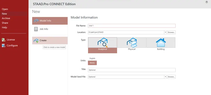
Open STAAD.Pro software.
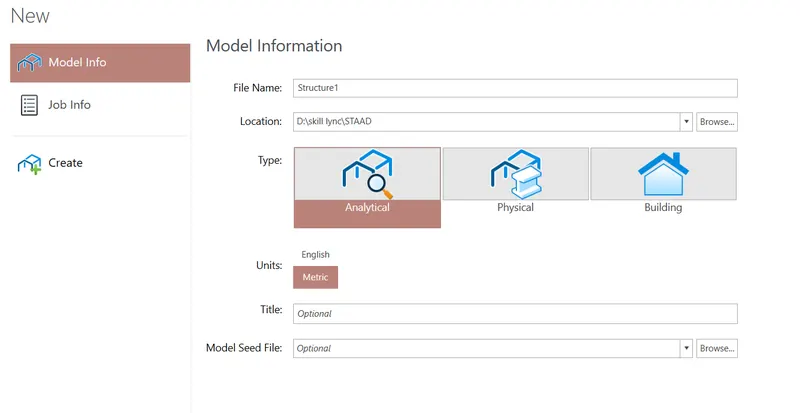
select New < Model Info.
make appropriate File name, Location, Units.
Select Create to go the Workspace and create a STAAD model.
Click on GEOMETRY TAB
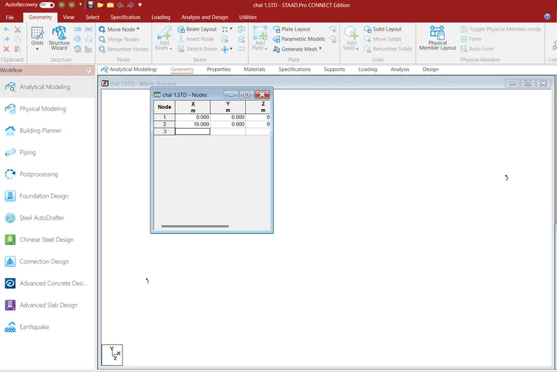
In Structure Pallette,Select Grids and choose Beam Grid
Enter the data to create Nodes in Nodes Column
Node 1 : X=0, Y=0
Node 2: X=16, Y=0
we can see that Two nodes are created at the distance of 16m.
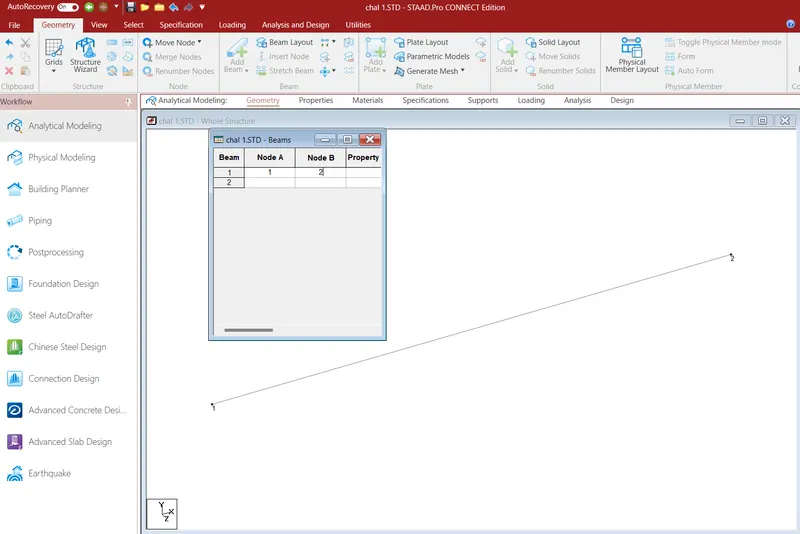
Enter the data to create Beam in Beams Column
Node A: 1 and
Node B: 2
Beam is created of Length 16m.
Click on PROPERTIES
Properties dialogue box opens
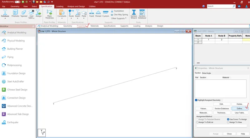
Click on Define
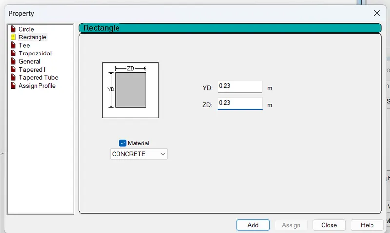
Add the Section here
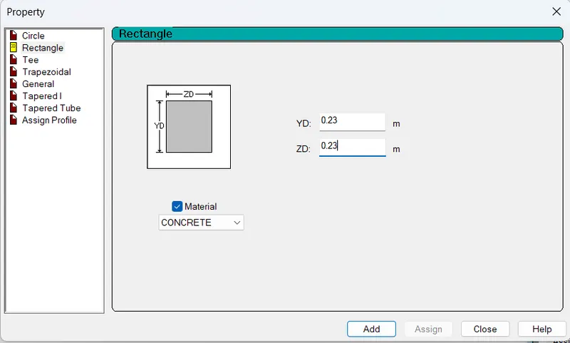
Select Rectangle and fill the data required.
YD= 0.23m, ZD=0.23m, Material = Concrete and
click Add.
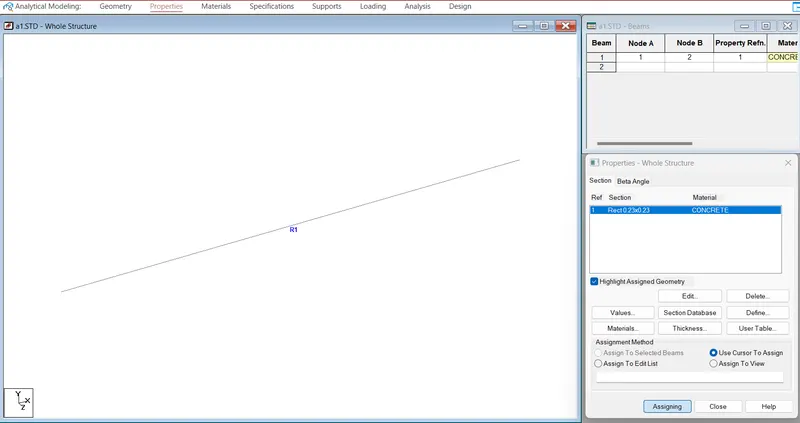
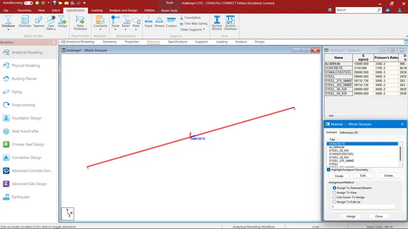
Select Materials, from the Material Tab and assign it to the created beam.
It can be checked by selecting the Concrete Title, then we can see that the created beam lines will be highlighted.
Select SUPPORTS TAB
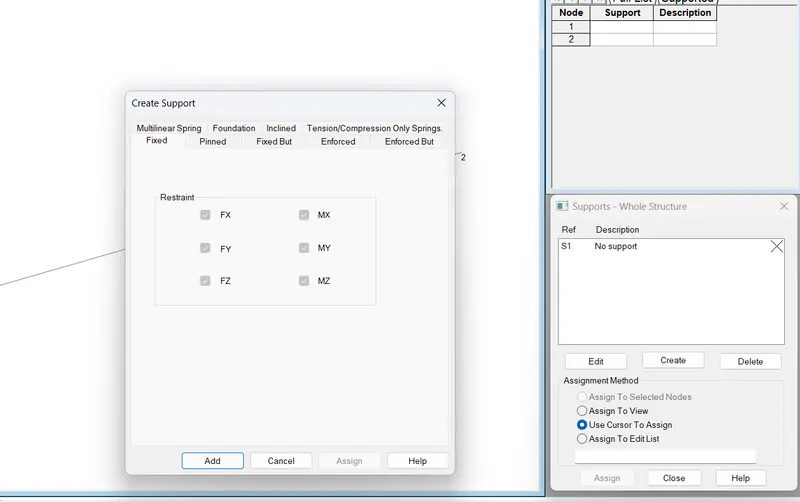
Supports-Whole Structure dialogue box opens
Click on create option
select Fixed and click Add.
For Roller support, click Create
select Fixed But and Release FX and MZ
click Add.
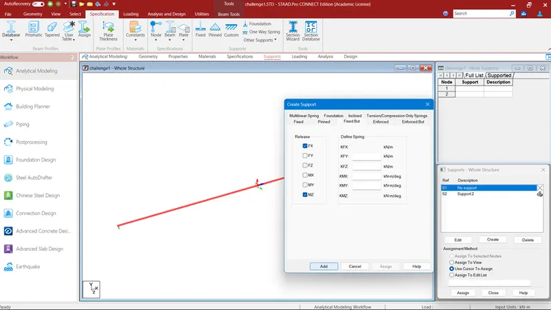
Then to assign Support at the two ends of beam,
Select Use Cursor to Assign option to assign the supports.
Click and select Support 2 (Fixed support) then using appropriate assigning method assign it in the Node 1 point.
Click and select Support 3 (Roller support) then using appropriate assigning method assign it in the Node 2 point.
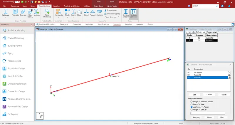
click Load Cases < Add < Add New : Load Cases.
Add New: Load Case dialogue box opens.
select Primary
Number = 1, Loading Type =Dead, Title = DL.
Select Dead Load(DL)
click Add < Selfweight < Selfweight Load < Direction = Y, Factor = -1.
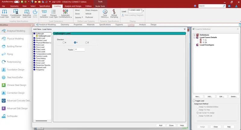
Click on Load & Definition Tab
click Load Cases < Add < Add New : Load Cases.
Add New: Load Case dialogue box opens.
select Primary
Number = 1, Loading Type =Live, Title = LL.
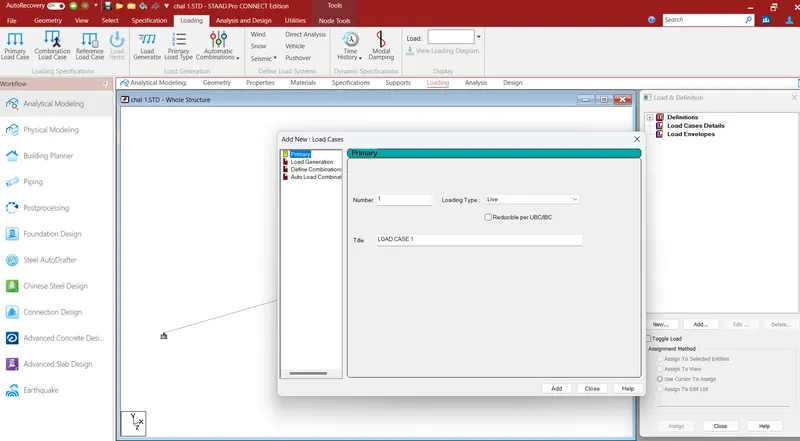
Select Live Load (LL)
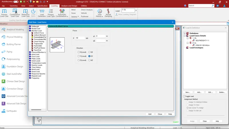
click Add < Member Load < Concentrated Force < P = -50, d1 = 8m, Direction = GY.
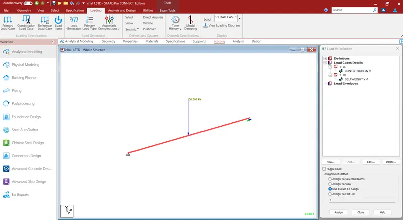
Select Use Cursor to Assign option to assign the Loads.
Select the Load and asssign the load to the beam.
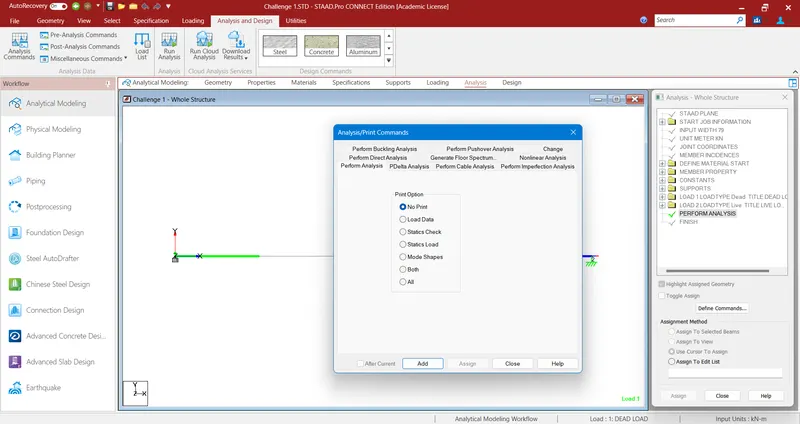
Click on ANALYSIS TAB
Analysis-Whole Structure dialogue box opens
Click on Define Commands
Analysis/Print Commands dialogue box opens
Select Perform Analysis
Print options : No print and
click Add.
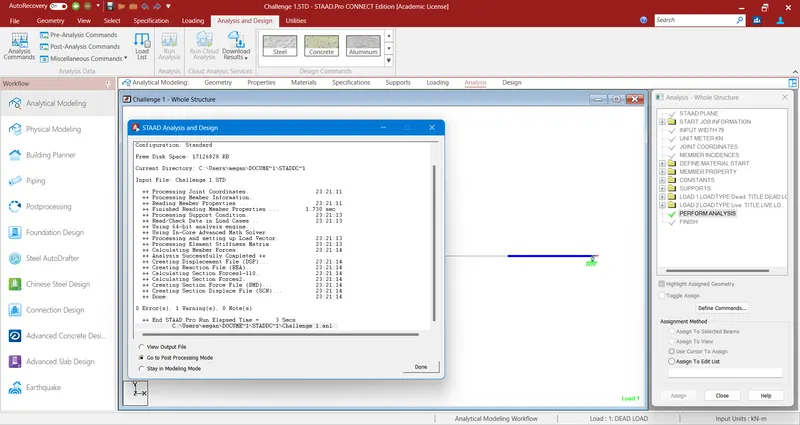
After adding Analysis/print command, click Run analysis.
Then we should get the Analysed model with 0 Errors
select Go to post proccessing Mode and click Done.
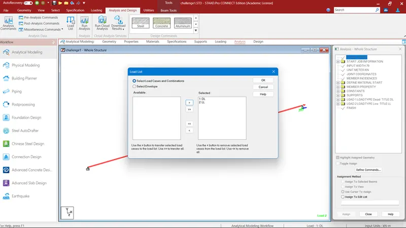
It will ask us to Select Load Cases and Combinations.
Select Created DL and LL,
Click OK to view Displacement of applied Load cases.
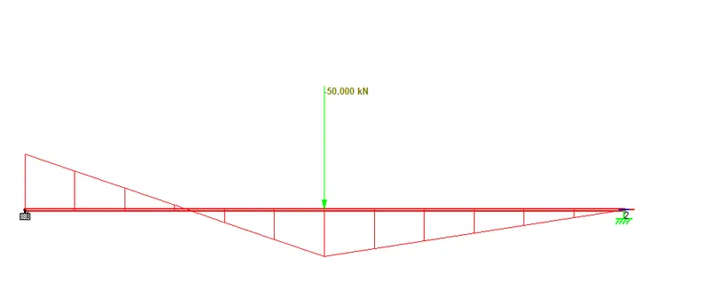
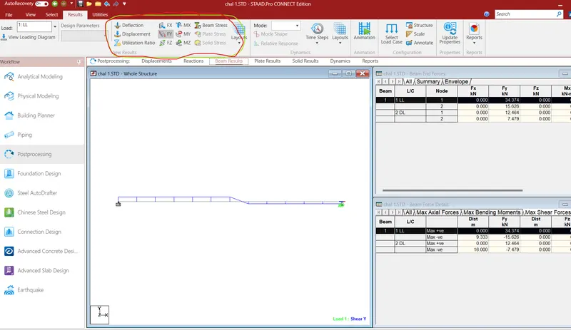
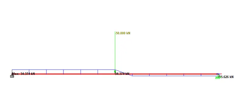
Here we can see the SFD and BMD for the applied load cases on the model.
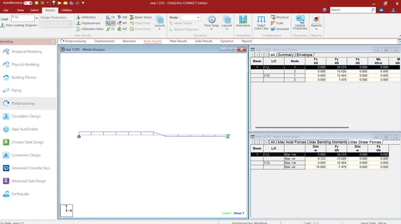
To view SFD of the model select FY icon present at the toolbar.
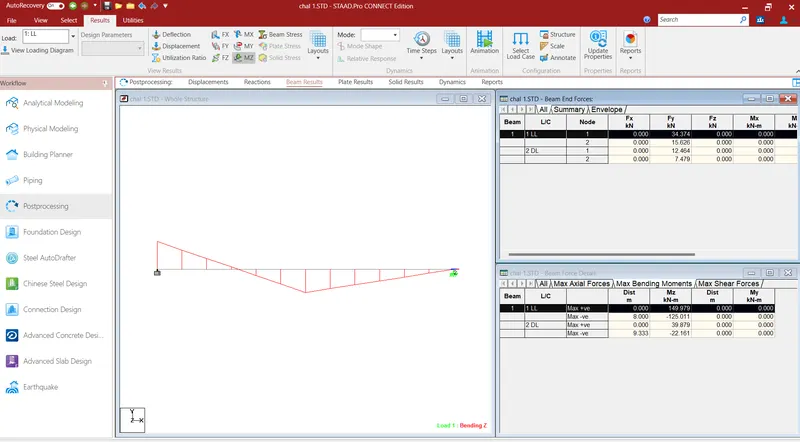
To view SFD of the model select Mz icon present at the toolbar.
RESULT: -
Created a STAAD Model with the mentioned Specification.
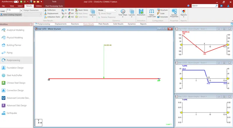
Drawn SFD and BMD using software
S.F.D
B.M.D