Week 1 Challenge
1.
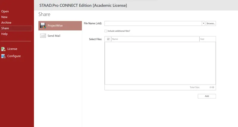
1ans: click on Staad pro software open it and select the share and send mail
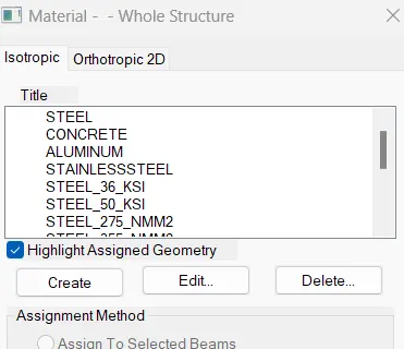
2.. Name the different materials that can be designed using STAAD Pro
concrete
aluminum
steel
stainless steel
3.. Is it possible to capture images in STAAD Pro? If yes how?
Ans. go to post processing and select the take picture
4.Name the three ways by which you can create a model.?
Ans: geometry, prototype, entering coordinate value
5. Write the steps followed to assign properties in a model.?
-select the properties
- define the shape is rectangle-beam
-material is select the concrete add and select the concrete, assign to view and assign.
2.
1.Name any six-design parameter involved in RCC design.
Ans: -compressive strength
-Fy-HYSD steel bars strength
-minumum reinforcement
-maximum reinforcement
-cover top and bottom
-Depth
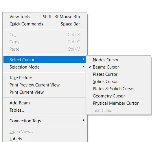
2.What are the different cursor types available in STAAD Pro?
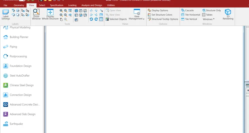
3. How will you generate different views for a model? State the steps involved.
go to view tab create the different views
4. Explain the procedure to define a “Simply Supported” condition in STAAD Pro
go to supports and create support is pined are fixed select the pin and add the supports by using use cursor to assingn,assign at supports.
5.Name any five topics that you will include while creating DBR.
1.structural layout
2.load and load combinations
3.analysis methods
4.design method
5.load calculations
6.Describe the term “Multi material design” of STAAD Pro.
Ans: It is used for 3D model generation, analysis and multi -material design. The STAAD. Pro supports several steel, concrete and timber materials in a separate member. This separate member will coordinate and then form into a structure.
3. 1. Name the structure systems in STAAD Pro? Explain each system?
Ans:
| Systems | geometry | loading | deformation | joints |
| space | 3D | 3D | 3D | Any |
| plane | 2D | 2D | 2D | Any |
| frame | 2D | r to xz | r t xz | Any |
| truss | 3D | 3D | 3D | pinned |
2. Explain the coordinate system adopted in STAAD Pro software.
Global co-ordinate system: global axis in Staad pro is fixed and not variable
Local co-ordinate system: local axis in Staad pro is variable and depends on member orientation.
3.Elaborate DBR and its uses?
ANS: A design basis report or DBR is pretty functional to explain the ins & outs of the ongoing project, it consists of all the major and important structural details related to a project.
For example, if a new party is getting involved in the building project due to some reason, then they can have an exact idea of the structural integrity of the building by reading the design basis report.
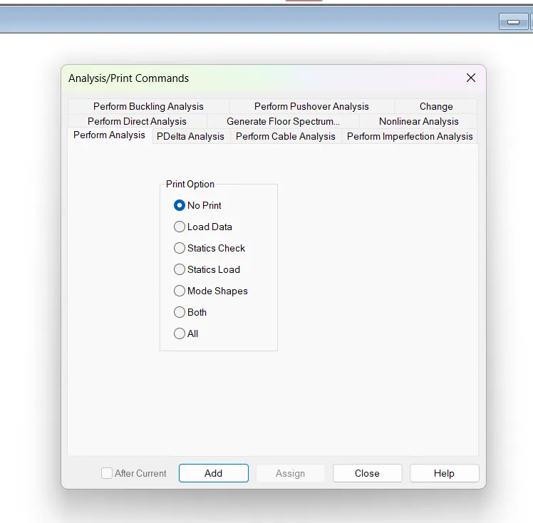
4. Explain the different types of analysis options in STAAD pro.?
Ans: It can make use of various forms of analysis from the traditional static analysis to more recent analysis methods like p-delta analysis, geometric non-linear analysis, Pushover analysis (Static-Non Linear Analysis) or a buckling analysis.
5. Explain the difference between Fixed and Fixed But condition.?
ANS:
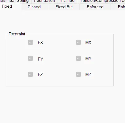
Fixed condition:
- Fixed is the end condition where all degrees of freedom are horizontal, vertical and moment are restricted.
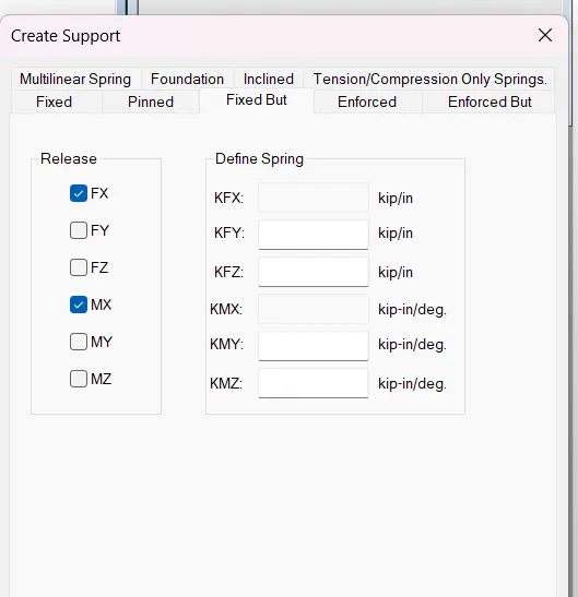
- On the other hand, fixed but customized end conditions where you can release some of the required degrees of freedom. as shown below.
restraint the all forces and moments
BUT fixed: when we create the roller support release the one restraint force Fx and one moment restraint Mx
Practical
1. Create a STAAD Model with the following Specification
a. A beam of span 16m
b. Support: Fixed on one end and Roller support (Horizontal) on the other end
c. A point load of 50 kN at the mid-point
d. Draw SFD and BMD using software
ANS:
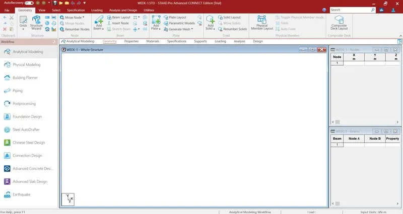
- Open up the software and create a new model.
- The first step is to initiate the project in STAAD.
- The same can be done by clicking on the new option available on the staad inro screen.
- After clicking on the new model, you can feed the project details.
- Also, you will be asked to specify a location within your system.
- Then, click on create to start a new project.
- Model the Beam of Required Span.
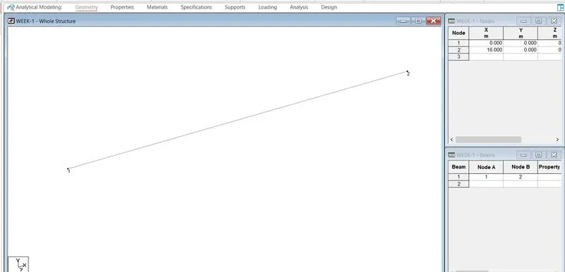
- To model the proposed beam, go to geometry and create the first node at x-0, y-0 & z-0.
- Then, select the created node by switching to the node cursor.
- Press Ctrl+C & Ctrl+V.
- Specify the span length that is 16 m in x-direction & enter.
- Both the ends of the required beams are created now go to add beam > select first node and then second to create a beam of the proposed length.
Nodes and Beams;
- Assign support conditions.
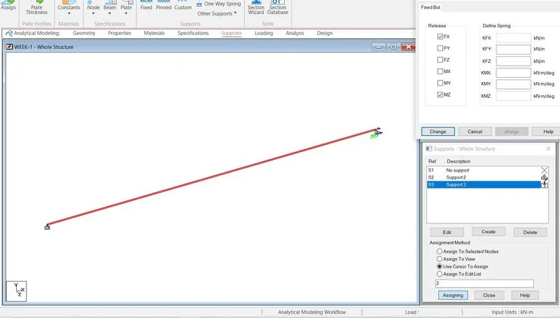
- Go to support > fixed > select one node > assign to selected nodes > enter.
- Similarly, create another node > fixed but >release moments and horizontal restraints > OK > select the other node > assign to selected > OK.
- Assign the proposed load.
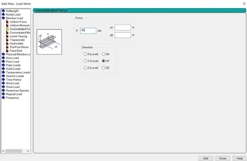
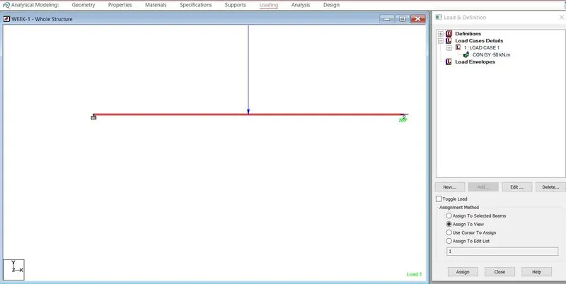
- Go to loads > create > member load > global y > P= -50 KN > OK.
- Now, select the load and beam and check the radio button for assign to selected > apply > ok.
- Assign the section property and Run the analysis.
- To assign a concrete section to the drawn beam, go to properties > define > concrete rectangular > specify the typical dimensions > OK.
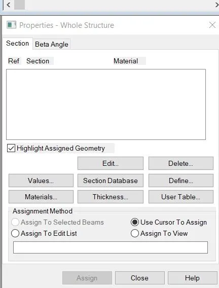
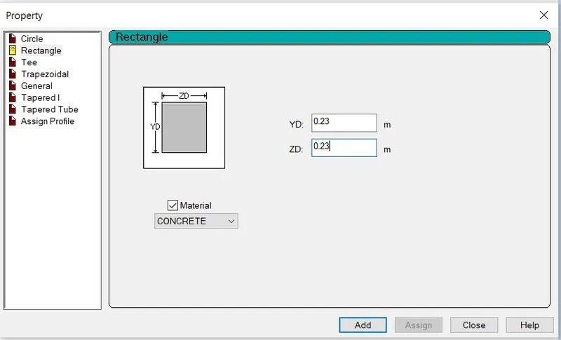
- Now select the beam and assign the section property by checking the radio button.
- After this, select the analysis method that is perform analysis from the design and analysis panel.
- Once you are done with setting up the analysis method ahead and run the analysis from the analysis and design panel.
- Wait some time for the analysis to get complete and look for errors and warnings.
- If there are no errors or warning signs upon completion of the analysis, you’re good to go.
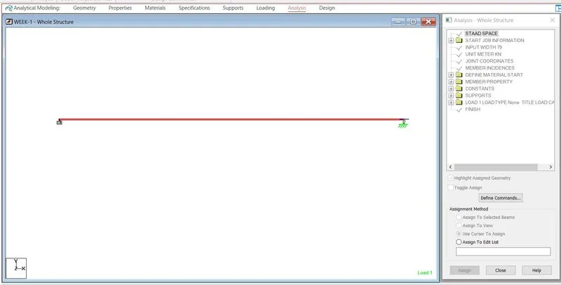
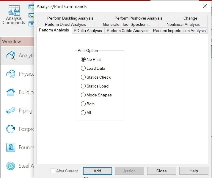
after Run-Analysis
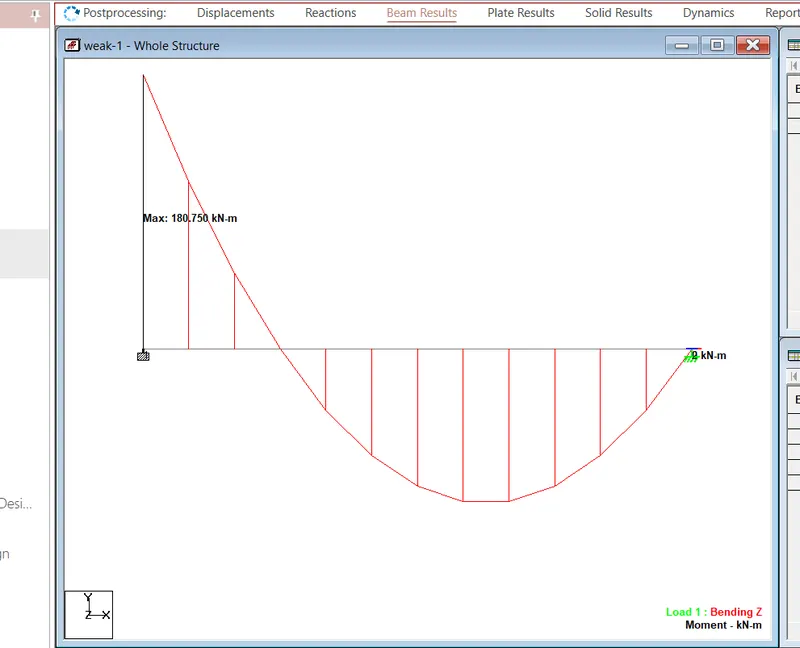
BEAM RESULTS:
bending moment
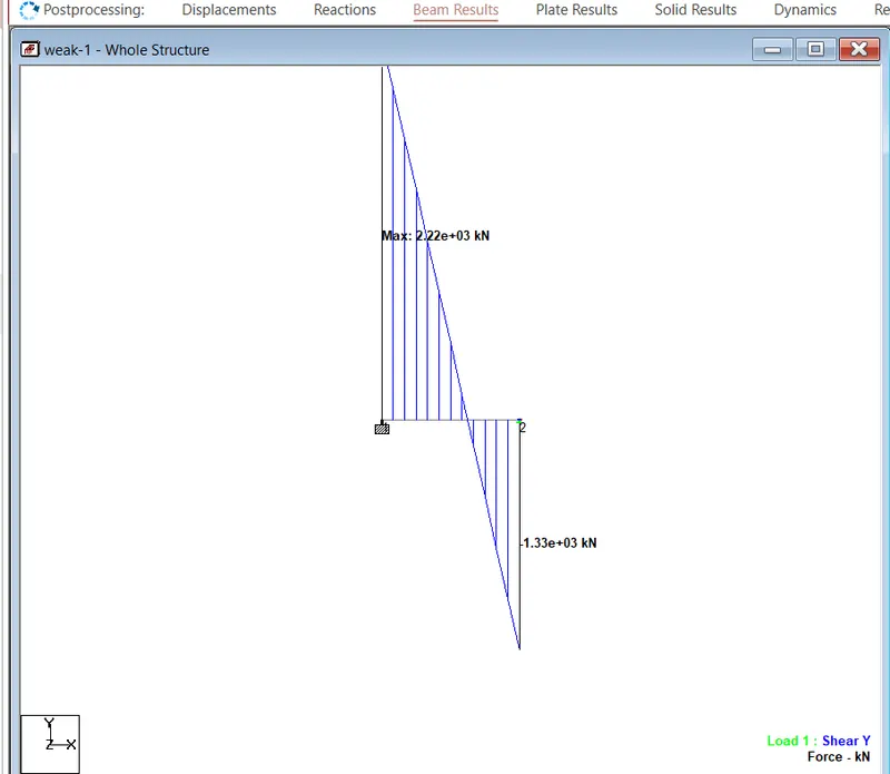
shear force
RESULT:
- Analysis & Design of Beam is created using STAAD Pro software successfully.
- Shear Force Diagram & Bending Moment Diagram is shown.