Week 1 Challenge
Q1.1. Write the steps involved to upload a .std file through web mail?
ANS :
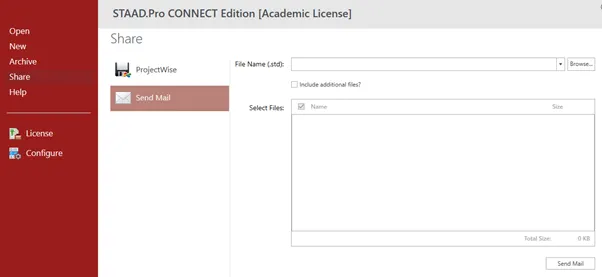
Open the STAAD.Pro software and click on Share which is at the left side of the screen and click on send mail and select the File name by clicking on the browse and select files by name and send the mail the by clicking send mail
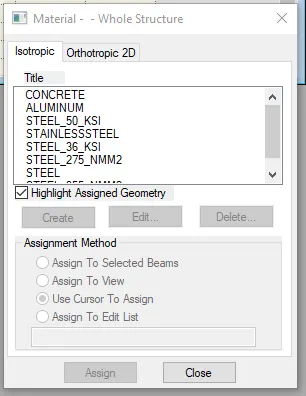
Q1.2. Name the different materials that can be designed using STAAD Pro.
ANS :
Concrete
Steel
Stainless Steel
Aluminium
Q1.3. Is it possible to capture images in STAAD Pro? If yes how?Yes,
ANS :
It is possible to capture images in STAAD.Pro
In utilities tab you will find a take picture option using this option we can capture a image

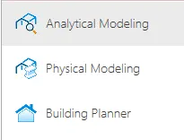
Q1.4. Name the three ways by which you can create a model.
ANS :
Analytical Modeling
Physical Modeling
Building Planner
Q1.5. Write the steps followed to assign properties in a model.
ANS :
Go to properties tab in that select define and define the beam shape and size after defining select the beam and select assign to selected beams and click on assign
Q2.1. Name any six design parameter involved in RCC design.
ANS :
Target Compressive strength, fck
Reinforced steel grade, fy
Cover
Depth
Minimum and maximum reinforcement
Bar diameter
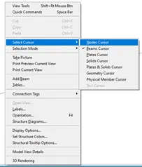
Q2.2. What are the different cursor types available in STAAD Pro?
ANS :
Nodes Cursor
Beams Cursor
Plates Cursor
Solids Cursor
Plates and Solids Cursor
Geometry Cursor
Physical Member Cursor
Text Cursor
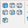
Q2.3. How will you generate different views for a model? State the steps involved.
ANS :
Go to view tab and choose the icon for isometric view, top view, bottom view, left view, front view, right view, back view
Q2.4. Explain the procedure to define a “Simply Supported” condition in STAAD Pro
ANS :
Create nodes and draw a beam then define properties and go to supports select create and choose pinned support for both the nodes to make it act like Simply Support beam
Q2.5. Name any five topics that you will include while creating DBR.
ANS :
Name and Location of the project
Introduction to construction methodology
Structural layout
Quality Assurance and Quality Control
Budget of the project
Q2.6. Describe the term “Multi material design” of STAAD Pro
ANS :
STAAD.Pro has in-built options and codes to design different materials like Steel, Concrete, Aluminium and Timber That’s why it is referred as multi-material design
Q3.1. Name the structure systems in STAAD Pro? Explain each system?
ANS :
Space, Frame, Plane, Truss
|
Structure system |
Geometry |
Loading |
Deformation |
Joints |
|
Space |
3D |
3D |
3D |
Any |
|
Plane |
2D |
2D |
2D |
Any |
|
Frame |
2D |
ɹr to XZ |
ɹr to XZ |
Any |
|
Truss |
3D |
3D |
3D |
Pinned |
Q3.2. Explain the coordinate system adopted in STAAD Pro software.
ANS :
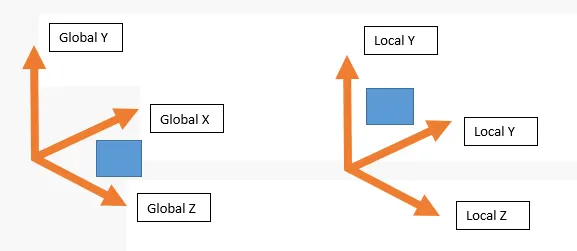
Global axis in STAAD.Pro is fixed and not variable
Local axis is variable and depends on the member orientation
Q3.3. Elaborate DBR and its uses.
ANS :
DBR – Design Basis Report. It is used to specify and compile the data required for analysis and design of structural elements of the project. It depicts the assumptions and specifications that are being used to develop the documents for a project. It will also help to avoid the scope creep that affect the project schedule and budget.
Q3.4. Explain the different types of analysis options in STAAD pro.
ANS :
Linear static analysis
Second order analysis
Non-Linear analysis
Member imperfection analysis
Pushover analysis
Q3.5. Explain the difference between Fixed and Fixed But condition.
ANS :
Fixed condition in the STAAD.Pro software is the condition where all the six degrees of freedom that is Horizontal or Vertical or moment are fixed
Fixed end condition in the STAAD.Pro software can be customized by its end condition accordingly, end conditions can be changed it is not restrained.
Practical
1. Create a STAAD Model with the following Specification
a. A beam of span 16m
b. Support : Fixed on one end and Roller support(Horizontal) on the other end
c. A point load of 50 kN at the mid-point
d. Draw SFD and BMD using software
ANS :
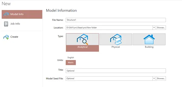
Open the STAAD.Pro Software and give the model information accordingly and click on create
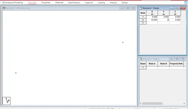
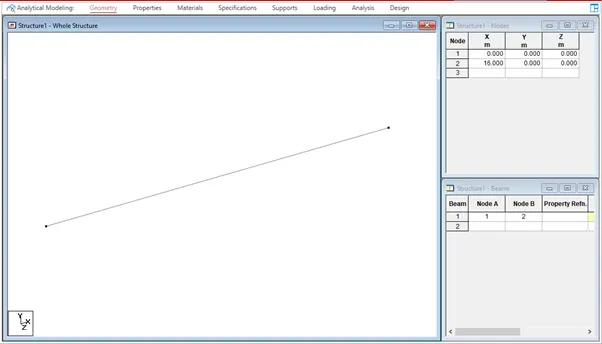
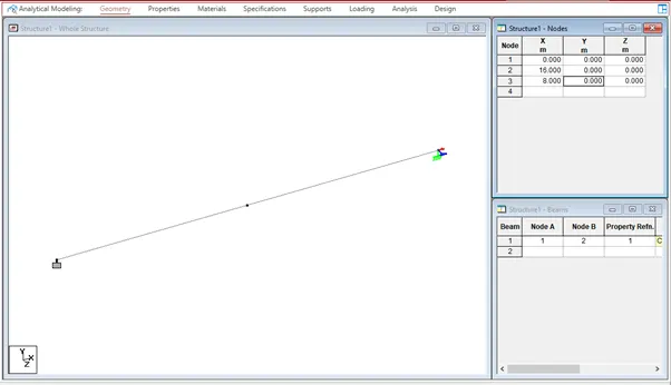
Create nodes by giving the values in the nodes dialogue box in Geometry tab
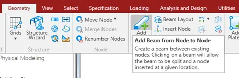
In geometry tab select add beam and draw the beam from one node to another node
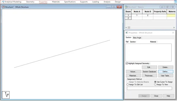
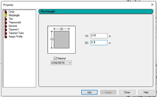
Go to properties tab in that select define and define the beam shape and size after defining select the beam and select assign to selected beams and click on assign
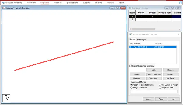
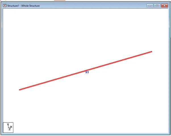
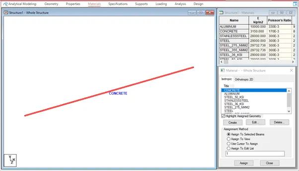
Go to materials tab and assign the concrete material to the beam
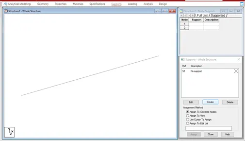
Go to supports tab and click on create and create fixed support and fixed but support and add the support and assign support to the each end
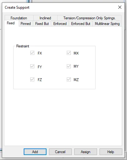
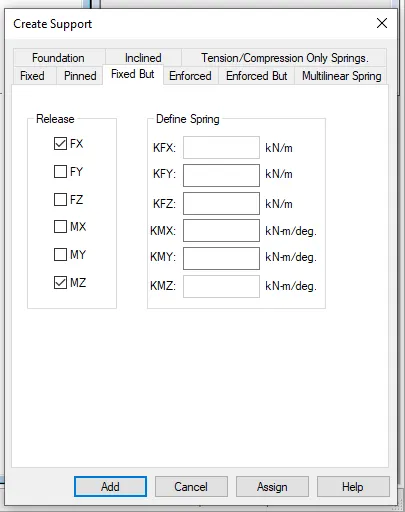
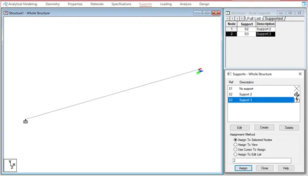
Since in the question the support is acting on the mid support so create a node at the mid span of the beam
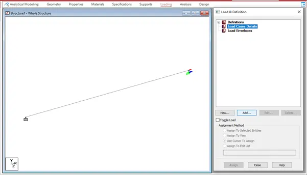
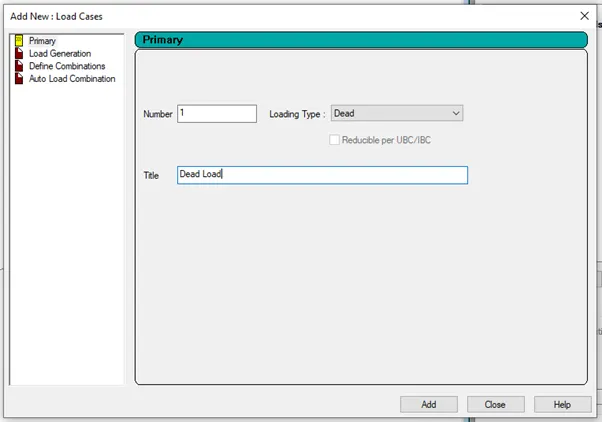
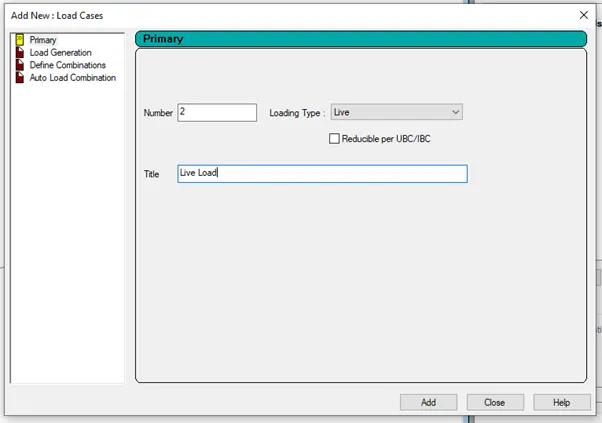
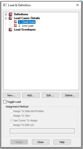
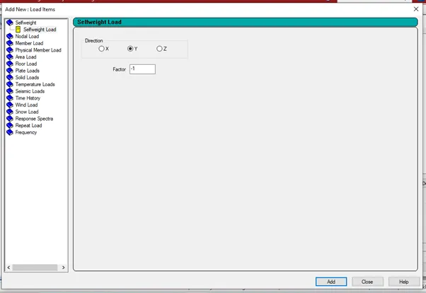
Go to loadings tab go to load cases details and add dead load and live load and assign the nodal load created in the live load at the mode created at the mid span
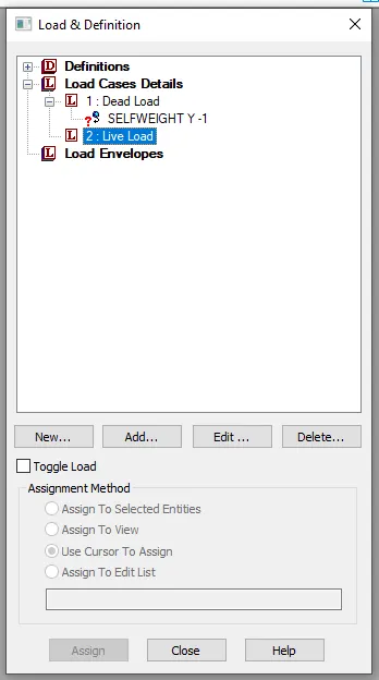
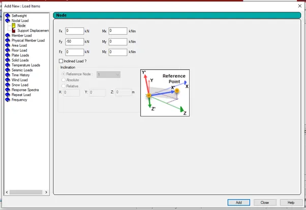
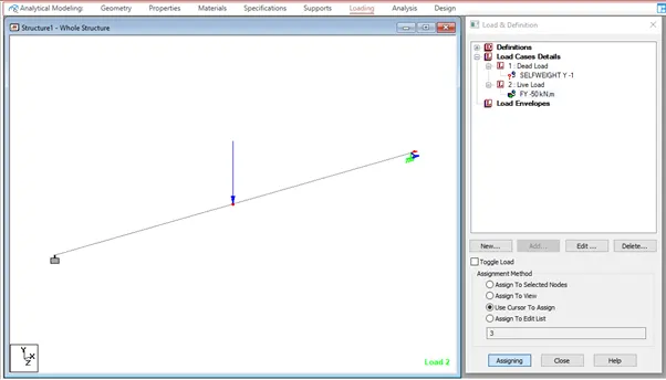
Go to analysis tab and do performance analysis and assign it and then analysis and design tab and run the analysis
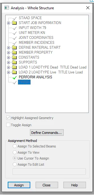

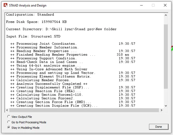
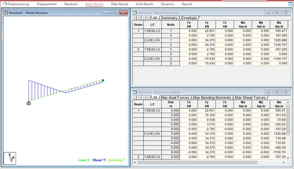
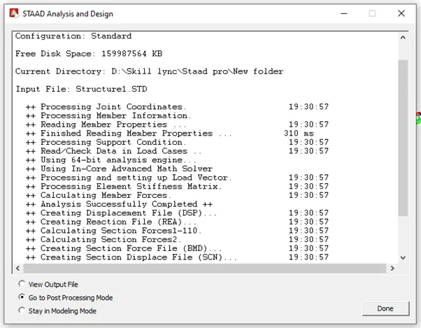
Go to post processing mode and click on done so that you can see Bending moment and shear force diagram
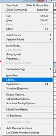
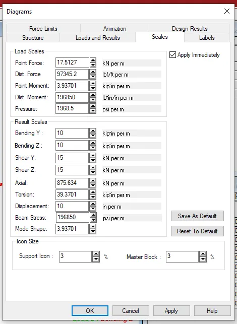
If the diagram is not visible properly right click select labels in that select scales change the scale values and click apply and then ok