Week 1 Challenge
1)1. Uploading a .std file through web mail are as follow:-
- Open software Stadd.Pro Connect edition.
- Select share option.
- Browse .std file and click add.
2. Different materials that can be designed using STAAD Pro. are as follow:-
- Concrete
- Aluminium
- Stainlessn steel
- Steel
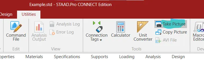
3. Yes, it is possible to capture images in STAAD Pro.
- Go to the Utilities Tab and Click on Take Picture.
4. Three methods to create a model in staad.pro are as follow:-
- Grid/snap node method
- Coordinate method
- Copy paste method
Notes:-By using these three methods a structure of any geometry can be created
Besides all the three method,structure wizard or prototype which is STAAD.Pro library of structure such as frames,trusses etc. is present.
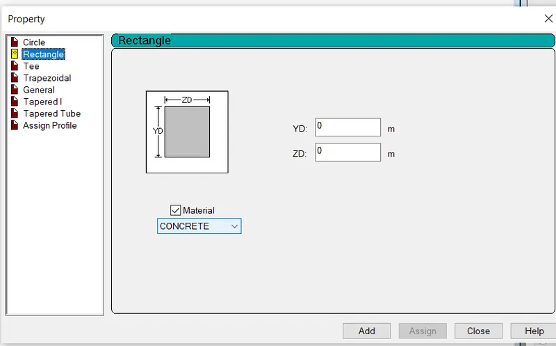
5. The steps followed to assign properties in a model.
- Open Stadd Pro
- Create a new project
- Go to the analytical Modeling
- Click on Properties
- Click on Define
- Select Property
- Give dimension SUCH AS WIDTH,THICKNESS etc.
- Then add and close
- Now assign property to the view
2) 1. The six design parameter involved in RCC design are as follow:-
- Characteristics compressive strength ( Fck ):- denote grade of concrete eg/M25,M30
- Charactersitcs tensile strength of steel (Fy):- denote grade of steel eg/fe415,fe500
- Cover:-resist steel from corrosion in RCC
- Depth
- Min & Max reinforcement
- Bar diameter
2. There are 8 different cursor in staddpro are as follow:
Beam cursor
- Plate cursor
- Solid cursor
- Plate and Solid curosr
- Geometry cursor
- Physical Member cursor
- Text Cursor
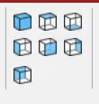
3. To generate different views for a model:-
-open/create a model in analytical modeling window
-Go to the view tab.
-Click on different types of views.
- Isometric View
- Top view
- Bottom view
- Left view
- Right view
- Front view
- Back view
4. Create two nodes using the grid option.now the two nodes denote the end of beams.
Select the nodes using node cursor and go to sup[port-create- pinned aat one node and roller at another node to make it like as SS beam.
5. The topics to create DBR.
- Introduction
- Structural Layout
- Loads and combinations
- Analysis and design Methodology
- Framing plans
- Load calculation
- Appendix
6. Multi material design” of STAAD Pro.:-it has in built option and has codes to design different material like
- Concrete
- Steel
- Aluminium
- Timber
or can create any type of material by providing material property like E value, density, poission ration or design propeties, means various or multi material can be created thats why called Multi material design.
3) 1.Following are the structure systems in STAAD Pro.:
-
There are four structural system in STAAD PRO software and they are as follows :-
STRUCTURE SYSTEM LOADING DEFORM GEOMETRY JOINT Space 3D 3D 3D ANY Plane 2D 2D 2D ANY Frame perpendicular to XZ Perpendicular to XZ 2D ANY Truss 3D 3D 3D PINNED
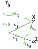
2. Coordinate system adopted in STAAD Pro software.
Global Coordinates System:-it is fixed.
This coordinate system is a rectangular coordinate system (X, Y, Z) which follows the orthogonal "right hand" rule. This coordinate system may be used to define the joint locations and loading directions. The translational degrees of freedom are denoted by u1, u2, & u3 and the rotational degrees of freedom are denoted by u4, u5, & u6.
- Design Based Resport. It is created before project start as a basic reoprt.
- DBR is use to specify and compile the data required for analysis and design of structural element in the project.
- Its represent the assumption and specification that are being used to develop the construction document for the project.
- It help to aviod the "Scope Creep" that can derail the project schedule and lead to budgets overruns.
4. Types of analysis options in STAAD pro.
- Perform analysis:- it is linear static analysis as a first order analysis for small buiding.
- PDelta analysis:- it is second order analysis.
- Non-linear analysis:- it is done in eathquake zone for high rise building.
- Perform Buckling Analysis
- Perform Direct analysis
- Perform Pushover analysis(Deformation)
- Perform Cable analysis
- Perform Imperfection analysis
5. The difference between Fixed and Fixed But condition.
Fixed support:-All six degree of freedom is fully restrained(Fx,Fy,Fz,Mx.My,Mz) assumes the displacement at fixed support ( i.e translational and rotational) to be known quantities and whose value is zero.
Fixed But support:-any degree of freedom are assigned assumes the displacement to be known quantities whose value may or may not be zero as spring constant is defined.
notes:- we can create roller support from fixed but support.
Practical
1. (a)
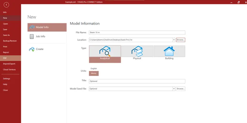
- Open Stadd.pro
- Name the file
- Choose analytical model
- Choose Metric
- Click on create
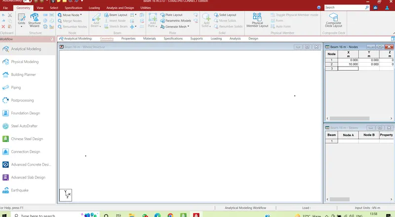
- Go to Geometry.
- Give ditance as 16m in Table
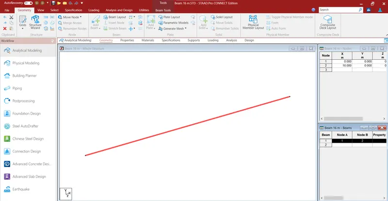
- Add beam and draw from start point to end Point.
- Assign the Property as rectangle (Concrete).
b.)
- Go to the support.
- Create support.
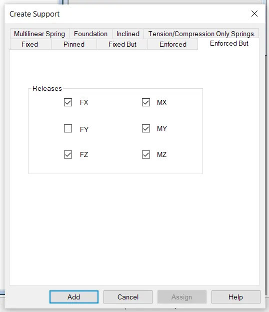
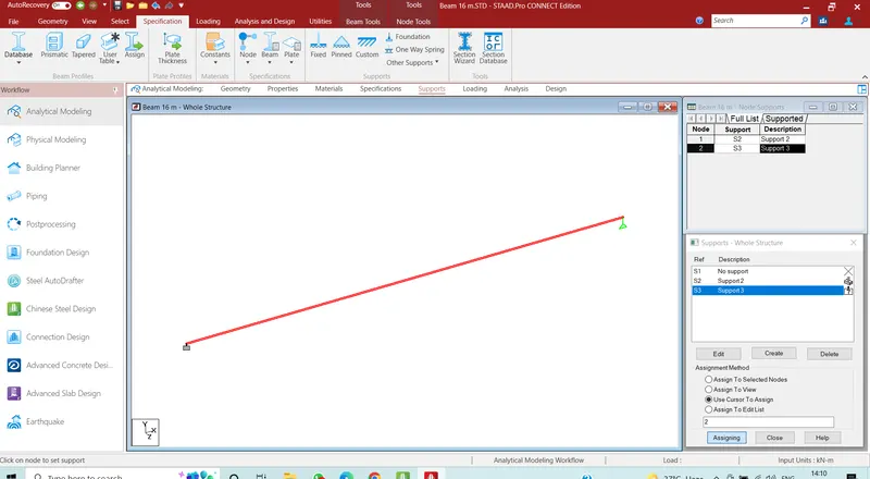
- 1st support is fixed in all ordinates.
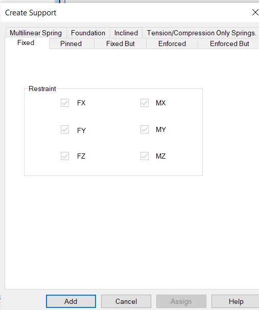
- 2nd Node is fix at only Fx.
- Create support < Go to Enfocrced But < and select only Fx.
- Now Assign the supports.
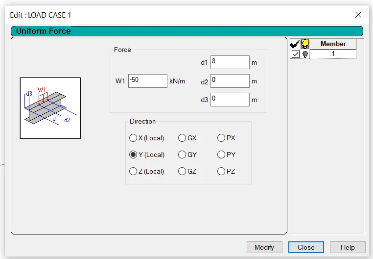
C) A point load of 50 KN at the mid of span
- Go to Load Option.
- Select Load case Details
- Add Load Case
- Click on ADD.
- Add Self Weight
- Agian Click on Add
- Click on Member Laod
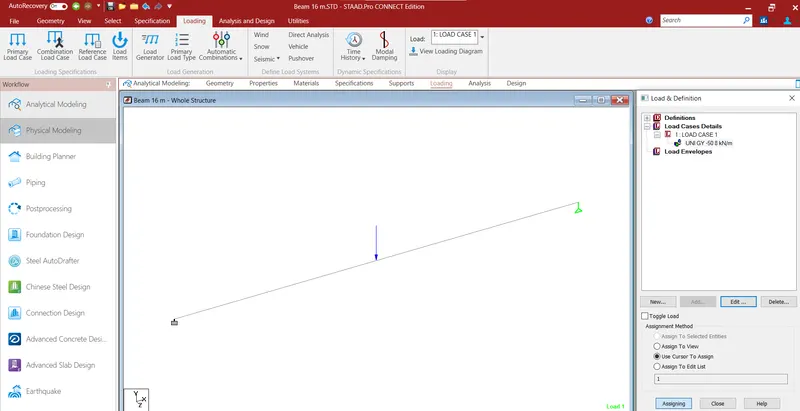
d) Draw SFD and BMD
- Now go to Analysis Tab
- Click on Analysis command
- Go to perform Analysis and ok.
- Run Analysis
- Save the file
- Showing error after analysis
- View Output to check error
- Resolve it in command file.
- Select space as plane
- Now reanalysis
- No error.
- Select the Postprocessing
- Select Displacement,shear force and bending Moment.
- Click on Annotate and tick on Shear and bending and displacement
- Click on scale and scale it as proper view.
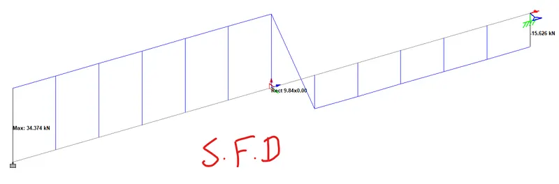
Select Fy
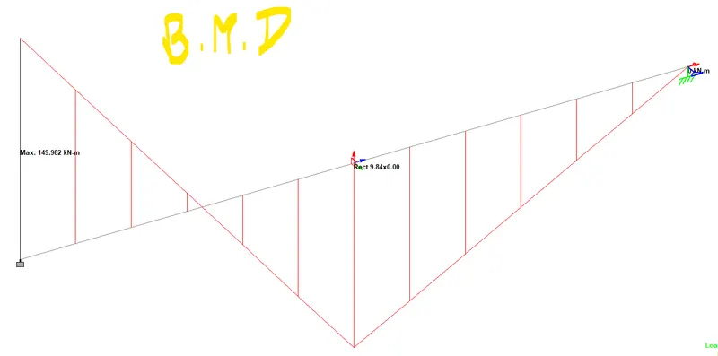
SELECT Mz
RESULT:-
Max. Shear Force = 34.374KN & MIN. S.F= 15.6 KN
Max. Bending = 149.982Kn-m & MIN. B.M=0 KN-m