Drafting of various geometries using Chamfer, Fillet tool in AutoCad
1.
- Aim:
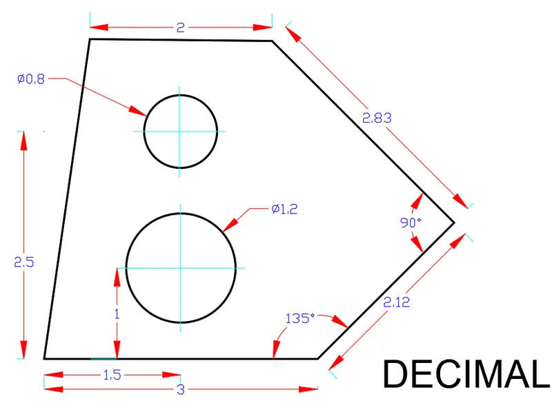
- To draw a drawing using decimal units
- The diagram to be drawn using line tool and circle tool in audocad
- Procedure:
- The value to be draw the drawing is in meters,hence change the units in templetes to meters
- Pick the line tool
- Draw a line for 3m
- Then a line for 2.12m at 45 degree
- Then a line 2.83m at 90 degree to line drawn before
- Draw a line of 2m towards 180 degree
- Now a line to close the drawing to the starting point
- Pick circle set point at 1.5,1m and draw a circle for 1.2m dia
- Again a point of 1.5,2.5 and a circle of .8m dia
- Then desired diagram is obtained
- Result:
- The drawing using decimal unit is drawn
- The drawing contains the dimension values in meter
- The drawing was completed using line tool
- AIM:
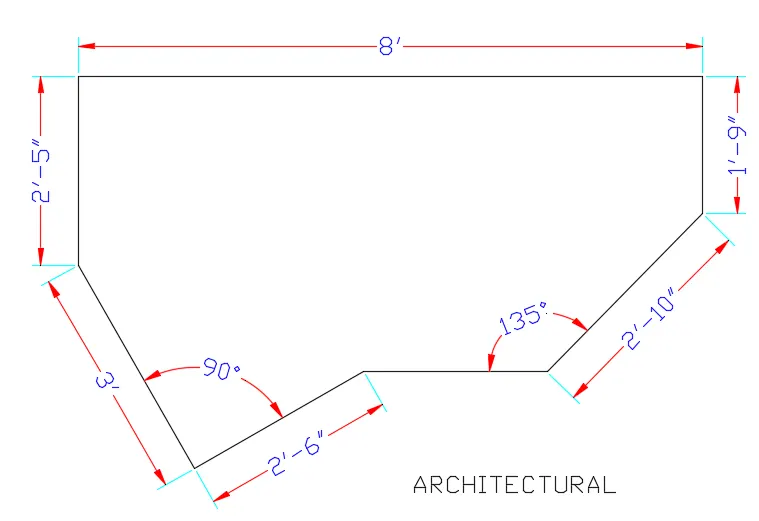
- To draw a drawing using architectural units
- The diagram to be drawn using line tool in autocad
- Procedure
- Pick the line tool
- Draw a line for 8'
- Then a line for 2'5" at 270 degree
- Then a line of 1'9"
- Now separetly draw a right angle having both arm lenth of 3' and 2'6"
- Similarly draw a 135 degree angle having one arm length of 2'10" and other of X line or desired length
- Now finally move all three and join to form given drawing
- Trim unwanted length
- Result
- The drawing using architectural unit is drawn
- The dwaing contains the dimension in feet in inches
3.
- AIM:
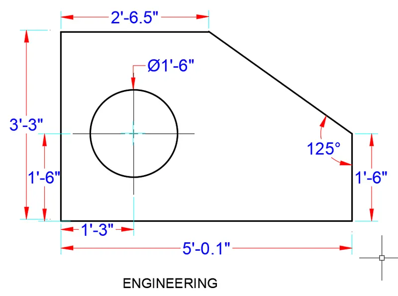
- To draw a drawing using engineering units
- The diagram to be drawn using line tool in autocad software
- Procedure:
- Pick line tool
- Draw a line of 5'.1"
- Then a line of 3'3" at 90 degree
- Then a line 2'6.5" at 0 degree
- Draw a line 2'6.5" at 90 degree to the line drawn before
- Then to end of 5;.1" line and another line of 1'6" at 90 degree
- And finally join the line to the left line before
- Now a circle at 1"3",1'6" of dia 1'6"
- And thus desired diagram is obtained as follow
- Result:
- The drawing unit is engineering
- It contains all dimensions value in feet and inches
- It is completed using line and circle tool
4.
- AIM:
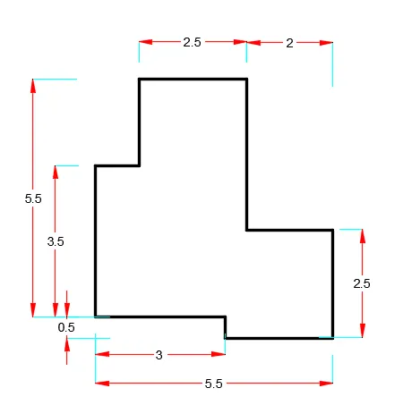
- To draw a drawing using decimal unit type
- The diagram to be drawn using line tool in autocad
- Procedure
- Pick the line tool
- Draw a line for 5.5m
- Then a line of 2.5m at 90 degree
- Then aline of 2m at 180 degree
- Draw a line of 3m at 90 degree to the line drwan before
- Then a another line of 2.5m at 180 and 2m at 270 and 1m at 180 and 3m at 270 and then 3m at 0 degree
- Then finally join it as follow
- Result:
- The drawing using decimal unit is drwan
- All dimension are mention
5.
- AIM:
- To draw a drawing using decimal unit type
- The diagram to be drawn using line tool in autocad software
- Procedure:
- Pick a line tool
- Draw aline for 11.5m
- Then a line of 6m at 90 degree and 11.5m at 180 degree
- Give the close command
- Then offset the line on both sides to 3m inside
- Now take a circle at point 1.5,3
- And draw circle of dia 1m and 2m at same center
- NBow take a circle atb point 5.75,3 of 3m dia
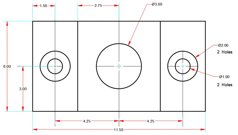
- Result:
- decimal unit is used
- dimension in meters
- line and circle tool is used
- 6.
- AIM:
- To draw a drawing using decimal unit type
- The diagram is drawn using line and offset tool in autocad
- Procedure:
- Pick line tool of line 1.5m at 270 degree
- A line of 2m at 180 degree
- Give close command
- Then offset the line at 90 degreeento .5m
- Now we got top view
- similarly other two are drawn
- we can also take several X- line horizontal ,vertical or inclined at given offset
- Give proper dimension and trim rest one
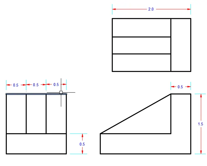
- Result:
- all dimension in meter
- decimal unit system is used
7.
- AIM:
- To draw a drawing using decimal unit
- The diagram to be drawn using line tool in autocad
- Procedure:
- The value to be used to draw the drawing is in meters hence change the unit in templets of autocad
- Pic a line tool
- Draw aline of 210m
- Then a line of 75m at 270 degree
- Then a line of 50m at 180 degree to the line drawn before
- Then to other end of the 210m line
- Draw a line of 100m at 270 degree
- Now aline of 70m at 0 degree
- Now pick the centre of 210m line
- Draw a line of 100m at 270 degree
- Now aline of 70m at 0 degree
- Now pick the centre of 210m line and mark a point 60m below
- And extend line both side
- Draw circle as given in question
- finally obtained as follow
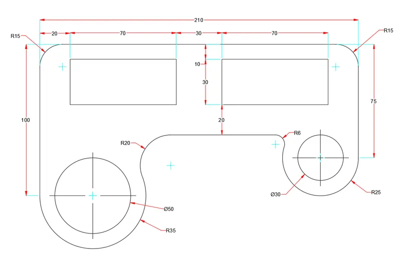
- Result:
- The drawing using decimal is draw
- The drawing contains dimension values
- The drawing was completed using line tool
8.
- AIM:
- To draw a drawing using decimal units
- The diagram to be drawn using line tool in autocad software
- Procedure:
- Pick a line tool and draw a line of 8.55m
- Draw two circle at dia 5 and 4 from same point at centre of line drawn
- Draw two circle of dia 0.9 and radius of 0.9m having centre at end of 1st line drawn to both end
- Now using tangent command and line join end outer and middle outer circle to both sides
- desired shape is obtained as follow
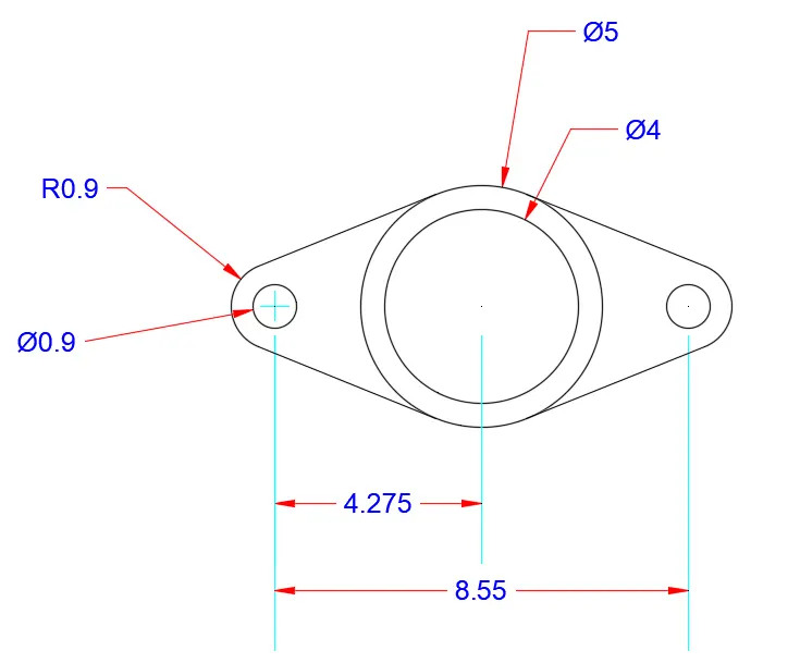
- Result:
- The drawing using decimal is draw
- The drawing contains dimension values
- The drawing was completed using line tool
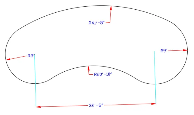
9.
- AIM:
- To draw a drawing using engineering units
- The diagram to be drawn using line tool in autocad software
- Procedure:
- Draw a arbitrary line of fixed length
- Draw circle to both end of line as centre of 8' and 9' radius
- Draw two more circle of radius 41'9" and 20'10" using "two tangent and radius" circle downwad
- Take tangent circle of 8' and 9' radius
- Now trim the rest and obtained drawing is as follow
- Result:
- The drawing using engineering is draw
- The drawing contains dimension values
- The drawing was completed using line tool
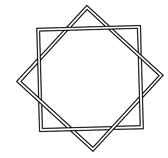
10.
- AIM:
- To draw a drawing using engineering units
- The diagram to be drawn using line tool in autocad software
- Procedure:
- pick rec tool
- Draw arbitary dimensions
- Take offset of 1st rectangle of 1'
- Now copy and rotate the 1st set of rec
- trim the rest as per drawing
- Desired shape is as follow
- Result:
- The drawing using engineering is draw
- The drawing contains dimension values
- The drawing was completed using line tool
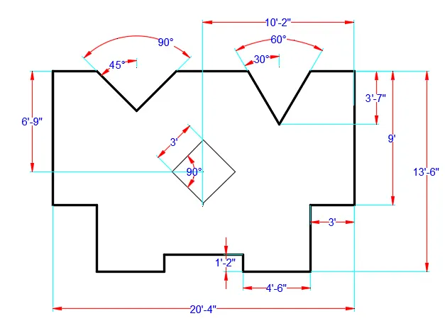
11.
- AIM:
- To draw a drawing using engineering units
- The diagram to be drawn using line tool in autocad software
- Procedure:
- Pick the line tool.
- Draw a line for 6'9" at 90
- Then a line for 20'4" at 0 degree.
- Then a line 3' at 180degree.
- Draw a line of 4'6" 2700degree to the line drwan before.
- Then to the end of 4'6" line at 180 degree.
- Then a line of 1'2" at 90 degrees.
- Then close the line
- Now a draw a V shape at the above line to the centre of the below line
- One V shape of 45 and 2'8"
- Another V shape of 30 degrees of 3'7".
- Now a cube of 3' at the middle of the draiwing.
- And thus desired diagram is got.
- Result:
- The drawing using engineering is draw
- The drawing contains dimension values
- The drawing was completed using line tool
- FINAL report:-
- 1.