Creating a Floor plan, Footing detail and Isometric view using AutoCad
1. Aim:
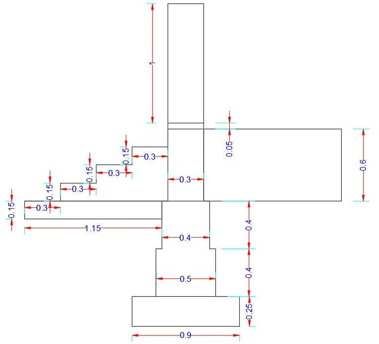
- To draw a cross section of load bearing wall over spread footing
- The diagram to be drawn using line and rectangle tool in autocad software
- Procedure
- The value to be used to drawn the drawing is in meters, hence change the units in the templets in autocad to meters
- First there is a rectangular shape which is PCC to be drawn using rectangle with length 0.9m and breadth 0.25m
- Then a line is drawn from centre of above edge of rectangle for .4m length
- then this line is offseted to .25m on both sides of the line as footing above PCC is 0.5m
- then the center line is extended for .4m for the head of the footing which is 0.4m in width
- for this the center line is drawn is offseted for 0.2m on both the side of line
- then the same center line is extended to 1m for the wall of thickness 0.3m
- where the center line is offseted for .15m on both sides
- then close the wall by connecting the two line at top
- then stair case is drawn
- the staircase is drawn with .15m as riser and 0.3m as thread
- the outcome of above procedure is given below
- Result
- the cross section of load bearing wall has been drafted
- the drawing contains dimension values
- the ddrawing was completed using line tool, rectangle tool,offset
2.
- Aim:
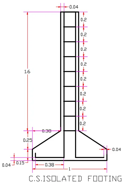
- To draw the cross section of the isolated footing
- the drawing is to be drawn using line tool
- Procedure
- The base of footing is initial drawing using a reectangle tool
- the rectangle of size 1m in length and 0.4m in breadth
- and then the upper cornor of the rectengle are chamfered
- it is done in distance mode by giving input of 0.38m as first point and 0.25m as second point
- hence the above formed edge is made as gap and the cornor of chamfer is connected with lines for a height of 1.6m
- and then line on both side are offseted 0.04m inside aline drawn to connected inner line
- then the line is offseted for a distance of 0.2m for 9 times
- the output of above procedure is given below
- Result
- The cross section of isolated footing has been drafted
- The drawing contains dimension value
- The drawing was completed using line tool
3.
- Aim:
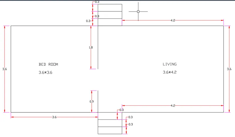
- To sketch the line diagram of a two bedroom building
- To follow dimension as per drawing
- To use line tool
- Procedure
- The line drawn is sketched by line
- Initially the line drawn for 3.6m length and 3.6m breadth completing it as arectangle
- and a 1m gap is provided for stair provision
- and then a rectangle is drawn for 3.6m length and 4.2m breadth
- Then the edge towards left of this rectangle is removed
- and a gap of .9m is made at right edge of the first rectangle at0.9m from below edge
- and the stair is drawn at that 1m gap for 0.3m offset for 3 times
- the above said procedure output is shown below
- Result
- The line drawing of a two bedroom building has been drafted
- The drawing contains the dimension value
- The drawing was completed using line tool
4.
- Aim:
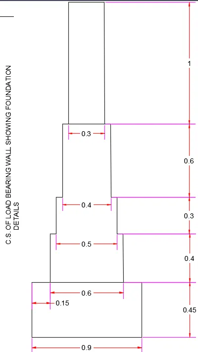
- To draw the cross section of load bearing wall showing foundation details
- The drawing is to be drawn using line tool
- Procedure:
- Initially a rectangle tool is used and a rectangle of 0.9m length and 0.45m breadth oi drawn
- Then a center line is drawn to a height of 0.4m
- And the center line is offseted for 0.3m on both side
- then the same center line is drawn for 0.3m height and offseted for 0.25m on both sides
- then the center line is drawn fuirther for 0.6m height and then offseted for 0.2m on both sides
- and finally the center line is elongated for 1m and offseted 0.15m on both sides
- then close the unjoint line
- and we will have the cross section of load bearing wall showing foundation details
- the output of above procedure ios shown below
- Result:
- The cross section of load bearing wall showing foundation detail has been drafted
- The drawing contains the dimension values
- Tohew drawing was completd using line tool
5.
- Aim:
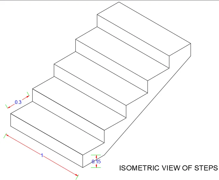
- To draw isometric view of steps
- To use isometric plane to draw the drawing
- Using line tool
- Procedure
- Initially turn the 2D plane to isometric plane
- Choose isometric right plane
- First point is plotted and 0.15m in z- axis is drawn a line of 0.3m in x- axis
- This is continue for 4 more times as there are 5 steps in total
- Then turn the plane isometric left and draw the straight line and now bring the same value 0.15 and 0.3m from top to down till it closes the starting end
- Then close all the paralle pontys
- Then we will have the steps in isometric view
- The output of the above procedure is shown below
- Result:
- The isometric view of the steps has been drawn
- Isometric plane has been used
- The output is attached to the procedure
6.
- Aim:
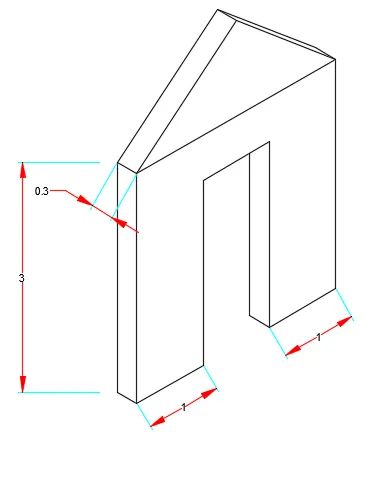
- To draw isometric view of gable wall
- To use isometric plane to draw the drawing
- using line tool
- Procedure:
- Initially turn the 2D plane to isometric plane
- then choose the isometric left plane draw aline 3m towards z direction
- then offset the line 0.3m and join the ends of the lines perpendicularly
- then a line in x direction ,then a center line to the line drawn in x for 1m
- connect the center line to the first created line
- draw the same in other x direction line
- and close the line
- now take the line towards down till the starting pont parallely
- then a 1m opposite x direction and a 2.42m in z axis
- then a 1m in opposite x direction
- then again downwards
- join the line to staring point
- the output of above said procedure ios shown below:
- Result:
- The isometric view of gable wall has been drawn
- Isometric plane has been usewd
- The output is attached to the procedure
- All the units are in meters