Creation of geometries by Coordinate system methods using AutoCad
- Aim:
- To create a geometries from p1 to p2 using all the coordinate systems which are as follows:-
- Absolute coordinate,Relative rectangular coordinate,Relative polar coordinates system
- Introduction
- Click Autocad icon from desktop (here i am using Autocad 2023 version)
- Then, before staring new drawing work, we have to set up some instructions which are follwing:
- click on Application menu
- next,click on NEW
- next,click on Create New,
- here, set the limits and units (imperal templetes ,decimal)
- Dynamic input button should be OFF,ON orthogonal mode
- Procedure
1.p1
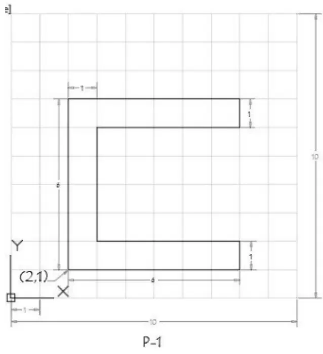
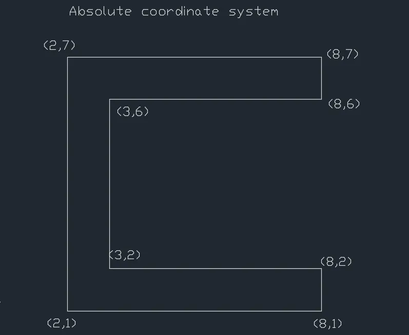
first ,solve drawing using absolute coordinate system:
- In Command bar,type "L" for line tool and press enter key
- specify first point: type 2,1 in command bar and press enter key(as a start point)
- specify next point:8,1 and press enter
- specify next point :8,2 and press enter
- specify next point:3,2 and press enter
- specify next point:3,6 and press enter
- specify next point:8,6 and press enter
- specify next point :8,7 and press enter
- specify next point:2,7 and press enter
- specify next point:2,1 and press enter(closing point will be starting point) or simply press CLOSE option in command bar and press enter
- Drawing
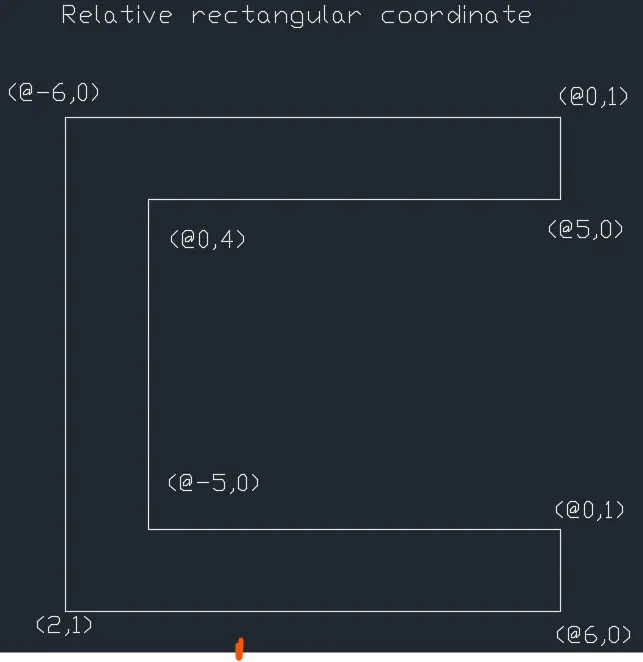
second,solve drawing using relative rectangular coordinate
Enter the line command and press enter key
- specify first point:2,1 and press enter key(start point)
- specify next point:@6,0 and press enter (second point DX=6,DY=0)
- specify next point:@0,1 and press enter
- specify next point:@-5,0 and press enter
- specify next point:@0,4 and press enter
- specify next point:@5,0 and press enter
- specify next point:@0,1 and press enter
- specify next point:@-6,0 and press enter
- specify next point:@0,-6 and press enter key or Close option and press enter key
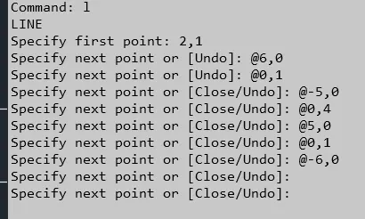
- Drawing
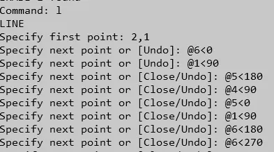
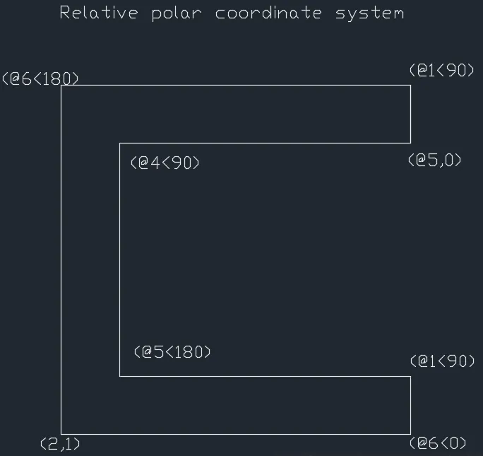
third,solve drawing using polar coordinate system
Enter line command and press enter key
- specify first point:2,1 and press enter
- specify next point:@6<0 and press enter
- specify next point:@1<90 and press enter
- specify next point:@5<180 and press enter
- specify next point:@4<90 and press enter
- specify next point:@5<0 and press enter
- specify next point:@1<90 and press enter
- specify next point:@6<180 and press enter
- specify next point:@6<270 and press enter or Close option and press enter key
- Drawing
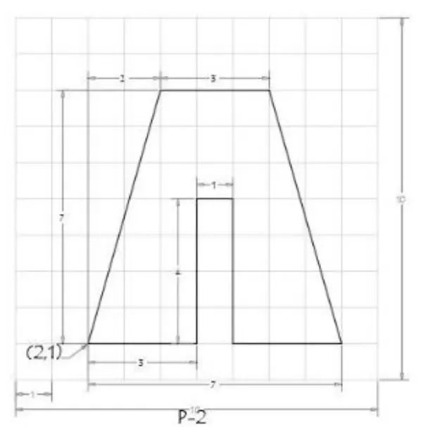
2.p2
- Drawing
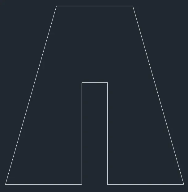
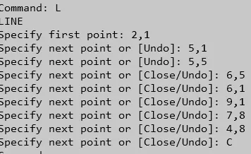
using absolute coordinate system:
Enter line command
- specify first point:2,1 and press enter
- specify next point:5,1 and press enter
- specify next point:5,5 and press enter
- specify next point:6,5 and press enter
- specify next point:6,1 and press enter
- specify next point:9,1 and press enter
- specify next point:7,8 and press enter
- specify next point:4,8 and press enter
- specify next point:select close option and press enter
using relative rectangular coordinate system
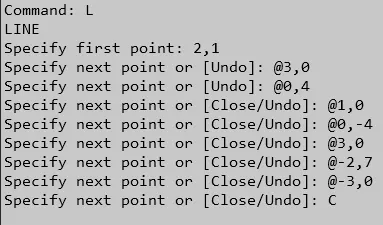
Enter line command
- specify first point:2,1 and press enter
- specify next point:@3,0 and press enter
- specify next point:@0,4 and press enter
- specify next point:@1,0 and press enter
- specify next point:@0,-4 and press enter
- specify next point:@3,0 and press enter
- specify next point:@-2,7 and press enter
- specify next point:@-3,0 and press enter
- specify next point:select Close option and press enter
using relative polar coordinate system
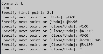
Enter line command
- specify first point:2,1 and press enter
- specify next point:@3<0 and press enter
- specify next point:@4<90 and press enter
- specify next point:@1<0 and press enter
- specify next point:@4<270 and press enter
- specify next point:@3<0 and press enter
- specify next point:@7<105.945 and press enter [tan-1(2/7)=15.945 since angle is measured from +X axis or east as a base i.e 15.945+90=105.945 degree]
- specify next point:@3<180 and press enter
- specify next point:select Close option and press enter
- Result:
- The given drawing was drawn with all coordinate system
- The line tool is used
- The imperial templates with units in feets and inches and angle base is east with decimal system is used
- The drawing was successfully obtained in all coordinate system
3.p4
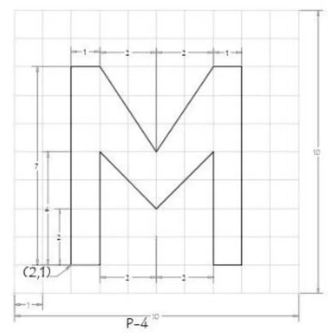
- Drawing

using absolute coordinate system:
Enter line command,
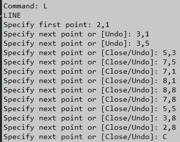
- specify first point:2,1 and press enter
- specify next point:3,1 and press enter
- specify next point:3,5 and press enter
- specify next point:5,3 and press enter
- specify next point:7,5 and press enter
- specify next point:7,1 and press enter
- specify next point:8,1 and press enter
- specify next point:8,8 and press enter
- specify next point:7,8 and press enter
- specify next point:5,5 and press enter
- specify next point:3,8 and press enter
- specify next point:2,8 and press enter
- specify next point:select Close option and press enter
4.p5
- Drawing
using absolute coordinate system
Enter line command
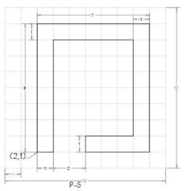
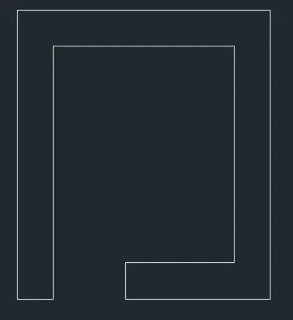
- specify the first point:2,1 and press enter
- specify next point:3,1 and press enter
- specify next point:3,8 and press enter
- specify next point:8,8 and press enter
- specify next point:8,2 and press enter
- specify next point:5,2 and press enter
- specify next point:5,1 and press enter
- specify next point :9,1 and press enter
- specify next point :9,9 and press enter
- specify next point:2,9 and press enter
- specify next point:select Close option and press enter
5.p7
- Drawing
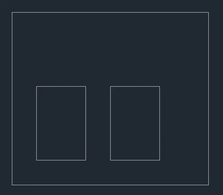
using relative rectangular coordinate system
Enter line command
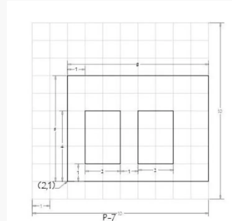
- specify first point:2,1 and press enter
- specify next point:@8,0 and press enter
- specify next point:@0,7 and press enter
- specify next point:@-8,0 and press enter
- specify the next point:select Close option and press enter
- here,1st outer drawing is closed
- As it has two other drawing inside it so select 1st point for both as absolute point and rest will be same
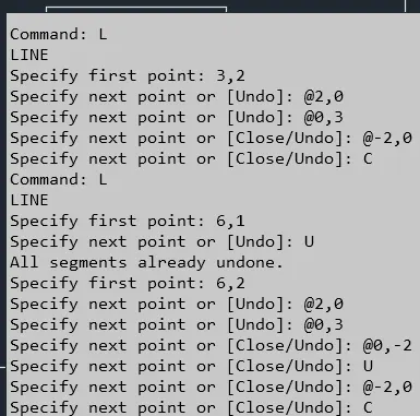
- enter line command
- specify first point:3,2 and press enter
- specify next point:@2,0 and press enter
- specify next point:@0,3 and press enter
- specify next point:@-2,0 and press enter
- specify next point: select close option and press enter
- for 2nd inside drawing, set first absolute coordinate and rest will same
- enter line command
- specify first point:6,2 and press enter
- specify next point:@2,0 and press enter
- specify next point:@0,3 and press enter
- specify next point:@-2,0 and press enter
- specify next point:select Close option and press enter
6.p8
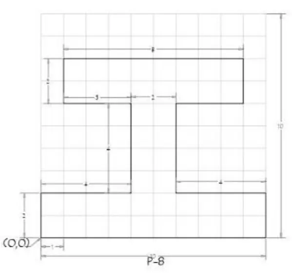
- Drawing
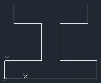
using relative polar coordinate system
Enter line command
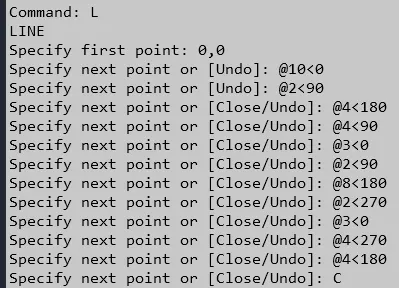
- specify first point:0,0 and press enter
- specify next point:@10<0 and press enter
- specify next point:@2<90 and press enter
- specify next point:@4<180 and press enter
- specify next point:@4<90 and press enter
- specify next point:@3<0 and press enter
- specify next point:@2<90 and press enter
- specify next point:@8<180 and press enter
- specify next point:@2<270 and press enter
- specify next point:@3<0 and press enter
- specify next point:@4<270 and press enter
- specify next point:@4<180 and press ente
- specify next point:select close option and press enter
7.p9
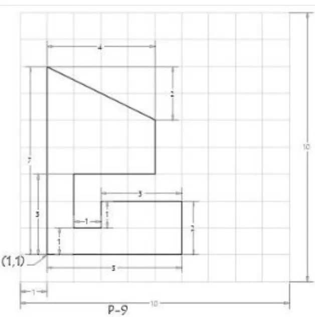
- Drawing
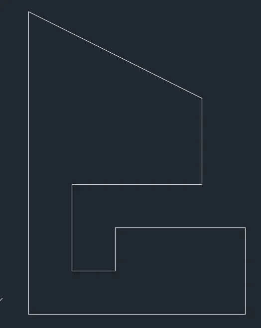
using relative rectangular coordinate system
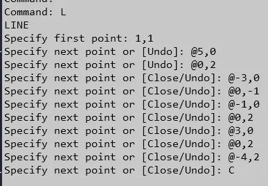
Enter line command
- specify first point:1,1 and press enter
- specify next point:@5,0 and press enter
- specify next point:@0,2 and press enter
- specify next point:@-3,0 and press enter
- specify next point:@0,-1and press enter
- specify next point:@-1,0and press enter
- specify next point:@0,2 and press enter
- specify next point:@3,0 and press enter
- specify next point:@0,2 and press enter
- specify next point:@-4,2 and press enter
- specify next point:select Close option and press enter
8.p10
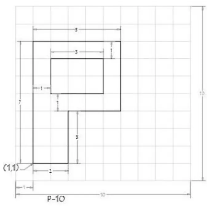
- Drawing
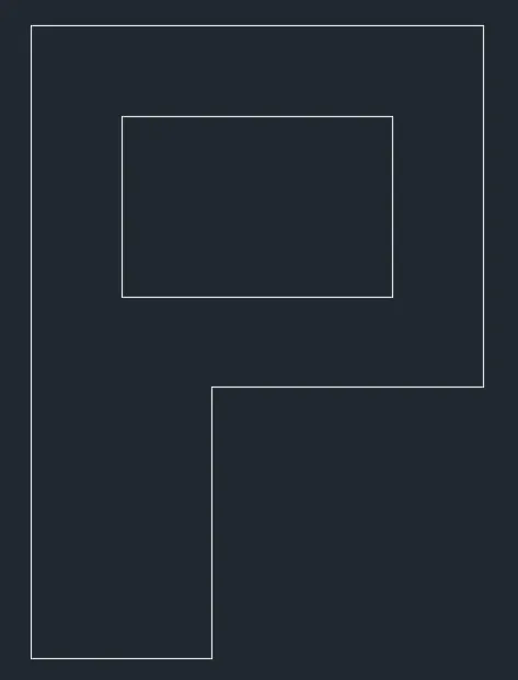
using relative polar coordinate system
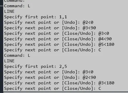
Enter line command
- specify first point:1,1 and press enter
- specify point:@2<0 and press enter
- specify point:@3<90 and press enter
- specify point:@3<0 and press enter
- specify point:@4<90 and press enter
- specify point:@5<180 and press enter
- specify point:select close option and press enter
- here,1st outer drawing is completed
- for inside drawing , fix 1st absolute point and rest will same
- specify first point:2,5 and press enter
- specify point:@3<0 and press enter
- specify point:@2<90 and press enter
- specify point:@3<180 and press enter
- specify point:@2<270 and press enter
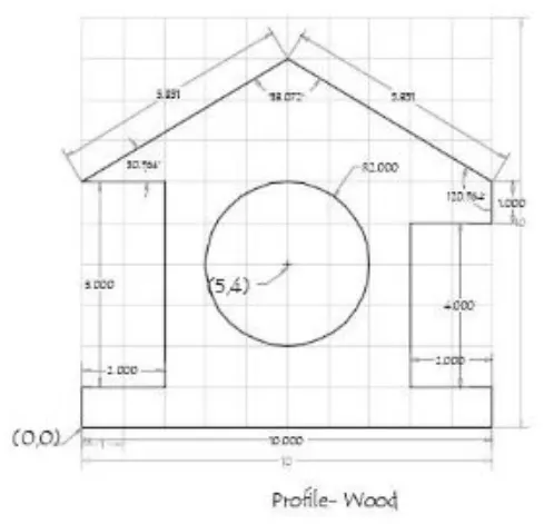
9. Wood truss structure
- Drawing

- Aim:
- To create a geometrical shape(profile-wood truss) using Relative polar coordinate system in Autocad software
- To create geometries using line tool and circle tool
- Procedure:
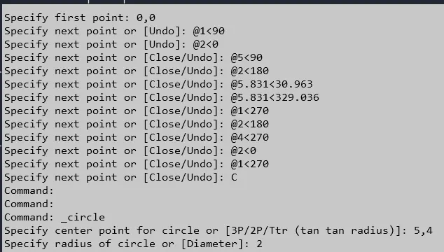
- specify first point:0,0 and press enter
- specify next point:@1<90 and press enter
- specify next point:@2<0 and press enter
- specify next point:@5<90 and press enter
- specify next point:@2<180 and press enter
- specify next point:@5.831<30.963 and press enter
- specify next point:@5.831<329.036 and press enter
- specify next point:@1<270 and press enter
- specify next point:@2<180 and press enter
- specify next point:@4<270 and press enter
- specify next point:@2<0 and press enter
- specify next point:@1<270 and press enter
- specify next point:select close option and press enter
- now, there is circle inside it having center's absolute coordinate (5,4) and radius as 2 unit
- enter circle command
- select circle and radius tool
- specify center point:5,4 and press enter,radius=2 and press enter key
- Result:
- The given drawing is drawn with relative polar coordinate system
- The line tool as well as circle tool is used
- The imperial templets with unit in inches and feet is used
- The drawing is successfully obtained in relative polar coordinate system
10.Queen truss
- Drawing
- Aim:
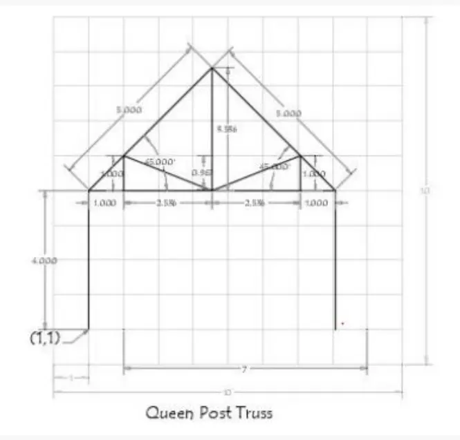
- To create a geometric shape (queen truss)using relative rectangular coordinate system in Autocad software
- To create geometry using line tool
- Procedure:
- we need to consider 4 origin
- 1st origin 1(1,1) for outer to outer face of str.
- 2nd origin 2(1,5) for horizontal straight line carrying truss
- 3rd origin 3(2,5) for truss member which are in zig - zag way above horizontal member
- 4th origin 4(4.535,5) for vetical line
- now proceed one by one as follow:
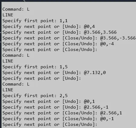
- specify first origin:1,1 and press enter
- specify next point: @0,4 and press enter
- specify next point:@3.566,3.566 and press enter
- specify next point:@3.566,-3.566 and press enter
- specify next point:@0,-4 and press enter and again enter
- enter line command
- specify second origin:1,5 and press enter
- specify next point:@7.132,0 and press enter and again press enter
- enter line command
- specify third origin:2,5 and press enter
- specify next point:@0,1 and press enter
- specify next point:@2.566,-1 and press enter
- specify next point:@2.566,1 and press enter
- specify next point:@0,-1 and press enter and again press enter
- enter line command
- specify fourth origin:4.566,5 and press enter
- specify next point:@0,3.566 and press enter
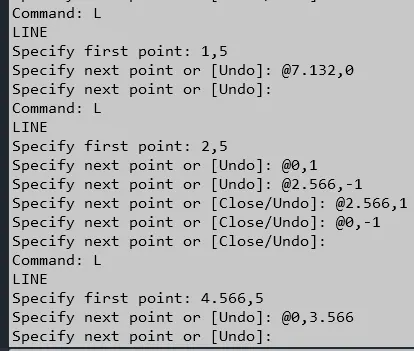
- Result:
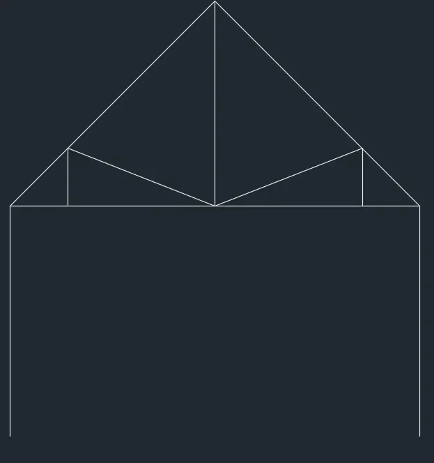
- The given drawing is drwan as per relative rectangular coordinate system
- The line tool is used
- The imperial templetes with units in feet and inches
- The drawing is successfull obtained
11.Mono pitch
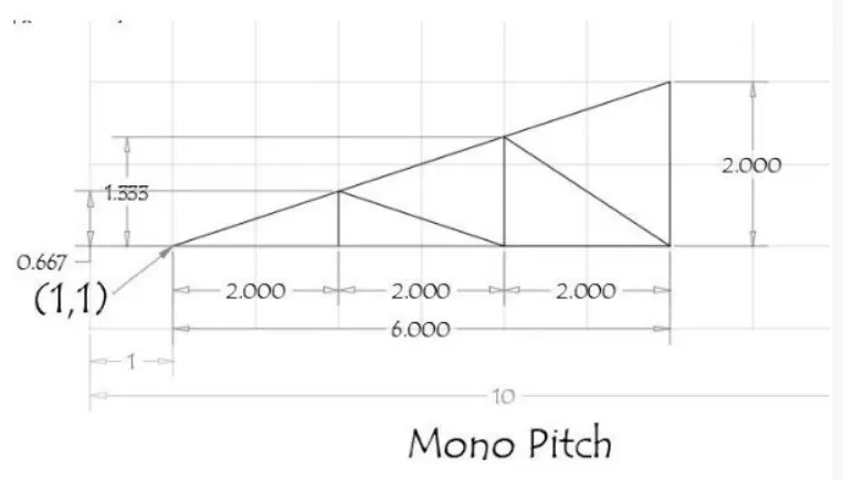
- Drawing
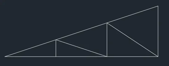
- Aim
- To create a geometric shape using relative rectangular coordinate system in Autocad
- To create geometry using line tool
- Procedure:
- Use relative rectangular system
- here ,two origin will be set to draw whole str.
- 1st origin 1(1,1) and 2nd will be (3,1) for outer and inner member of truss drawing respectively
- specify first origin:1,1 and press enter
- specify next point:@6,0 and press enter
- specify next point:@0,2 and press enter
- specify next point:select close option and press enter
- enter line command
- specify next point : select Close option and press enter
- specify 2nd origin point:3,1 and press enter
- specify next point:@0,0.667 and press enter
- specify next point:@2,-0.667 and press enter
- specify next point:@0,1.333 and press enter
- specify next point :@2,-1.333 and press enter
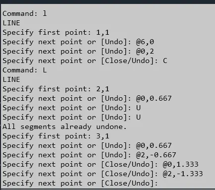
- Result:
- The given drawing is drawn as per relative rectangular coordinate system
- The line tool is used
- The imperial templetes with units in inches and feets
- The drawing is successfully obtained