Week 1 Challenge
I
1) Write the steps involved to upload a .STD file through webmail.
- Open the STAAD software and locate the share option available on the intro screen.
- After clicking on the share button, select send mail option.
- Then, browse for the. STD file on your machine and hit send.
2) Name the different materials that can be designed using STAAD Pro.
STAAD Pro can design the following different materials:
- Concrete
- Steel
- Aluminium
- Timber
- Composite Sections
3) Is it possible to capture images in STAAD Pro? If yes how?
It is possible to capture images in STAAD Pro. We can take pictures of models and structural results in STAAD pro using the take picture command.
4) Name the three ways by which you can create a model.
STAAD Pro allows to create three primary types of models to work on that are listed as follows:
- Analytical Model
- Physical Model
- Building Planner Model
5) Write the steps followed to assign properties in a model.
- Go to the properties panel.
- Click on materials.
- Select a desired material from the list (concrete/steel/aluminium/stainless steel)
- Then check the assignment method based on your preference like using cursor/assign to view.
- After checking the radio button, assign the material property to the model.
II
1) Name any six design parameters involved in RCC design.
- E - Modulus of elasticity
- Poisson's ratio
- Density
- Thermal coefficient
- Fy
- Fu
2) What are the different cursor types available in STAAD Pro?
- Nodes cursor
- Beams cursor
- Plates cursor
- Surface cursor
- Solids cursor
- Geometry cursor
- Loads edit cursor
- Support edit cursor
- Member release edit cursor
3) How will you generate different views for a model? State the steps involved.
In the top tool panel in the software, there are several cubes with one of their side colour filled. These are view cubes to generate the view of your choice be it 3D, top view, side view, front view, etc.
4) Explain the procedure to define a “Simply Supported” condition in STAAD Pro
- Go to the supports.
- Click on the create button.
- Select the pinned option from the list.
- Thus, a simply supported end condition has been created and now it can be assigned to the desired nodes.
5) Name any five topics that you will include while creating DBR.
- Name and location of the project.
- Structural layout.
- Loads and Load Combinations.
- Method of analysis and codes referred.
- Quality Assurance and Quality Control (QA/QC).
6) Describe the term "Multi-material design" of STAAD Pro.
STAAD. Pro has in-built options and codes to design different materials like steel, concrete, Aluminium and Timber that's why it is referred to as a "Multi-Material" design. The term multi-material design is typically used to define the structure that is designed by implementing more than one structural material.
III
1) Name the structure systems in STAAD Pro. Explain each system.
STAAD Pro has the following structure systems. They are explained below.
Space Frames
A space structure, which is a three-dimensional framed structure with loads applied in any plane, is the most general. Space frames are designed to carry loads for longer spans without intermediate supports.
Plane Frames
A plane structure is bound by a global X-Y coordinate system with loads in the same plane. Plane frames are the typical RCC or steel frame systems adopted for building construction.
Floor System
A floor structure is a two or three-dimensional structure having no horizontal (global X or Z) movement of the structure [FX, FZ & MY are restrained at every joint]. The floor framing (in the global X-Z plane) of a building is an ideal example of a FLOOR structure. Columns can also be modelled with the floor in a floor structure as long as the structure
Trusses
A truss structure consists of truss members which can have only axial member forces and no bending in the members. Trusses are constructed by arranging the structural elements in triangular formats to take up both tension and compression.
2) Explain the coordinate system adopted in STAAD Pro software.
STAAD Pro Physical Modeller uses a conventional Cartesian coordinate system, with the global Y axis assumed as vertical (i.e., "Y up", or the height of the structure is parallel to the global Y axis).
Global Coordinate System
This coordinate system is a rectangular coordinate system (X, Y, and Z) which follows the orthogonal "right hand" rule. This coordinate system may be used to define the joint locations and loading directions. The translational degrees of freedom are denoted by u1, u2, & u3 and the rotational degrees of freedom are denoted by u4, u5, & u6.
Local Coordinates
Each member or surface has its own local Cartesian coordinate system which is also oriented using the "right hand" rule.
The longitudinal axis of a member is the first axis, with the positive axis taken from the i to the j ends (i.e., Ni and Nj). The second axis is oriented such that the 1-2 plane is then parallel to the global Y axis. The third axis is then normalized to the first and second local axes as defined by the right-hand rule. The local 2 and 3 axes coincide with the two principal moments of inertia of the cross-section. In the special case of a vertical member (where the local 1 axis is parallel to the global Y axis; i.e., a column), the local 3 axis is then made parallel to the global Z axis and the 2 axis is oriented respectively.
3) Elaborate DBR and its uses.
A design basis report or DBR explains the ins and outs of the ongoing project. It consists of all the major structural details related to a project. It is used to specify and compile the data required for the analysis and design of structural elements of the project. It depicts the assumptions and specifications that are being used to develop the documents for a project. It will also cost help avoid the "Scope Creep" that can affect the project schedule and budget.
4) Explain the different types of analysis options in STAAD pro.
a. Linear elastic analysis
A linear static analysis is an analysis where a linear relation holds between applied forces and displacements. In practice, this applies to structural problems where stresses remain in the linear elastic range of the used material. In linear static analysis, the model's stiffness matrix is constant, and the solving process is relatively short compared to a nonlinear analysis on the same model. Therefore, for a first estimate, linear static analysis is often used before performing a full nonlinear analysis.
b. Direct analysis
This method can be applied to any type of structural member. It provides accurate results for the design of structural members like beams. It includes the required strength and available strength calculations. The direct analysis method includes the stability consideration for the structures. This stability in this method is provided for the whole structure and individually to all elements. It follows the following procedure:
- Analysis of the structure is performed at the strength level.
- The notional loads are applied on each floor level. These loads act as lateral loads which have less value.
- Stiffness for all the members which provides stability to the structure in the lateral direction is to be modified. The resistance offered by the members to the upcoming forces shows the stiffness of members.
c. Nonlinear analysis
A nonlinear analysis is an analysis where a nonlinear relation holds between applied forces and displacements. Nonlinear effects can originate from geometrical nonlinearity (i.e. large deformations), material nonlinearity (i.e. elasto-plastic material), and contact. These effects result in a stiffness matrix which is not constant during the load application. This is opposed to the linear static analysis, where the stiffness matrix remained constant. As a result, a different solving strategy is required for the nonlinear analysis
d. Nonlinear cable analysis
When all of the members, elements and support springs are linear except for cable and/or preloaded truss members, then this analysis type may be used. This analysis is based on applying the load in steps with equilibrium iterations to convergence at each step. The step sizes start small and gradually increase (15-20 steps are the default). Iteration continues at each step until the change in deformations is small before proceeding to the next step. If not converged, then the solution is stopped. You can then select more steps or modify the structure and rerun. Structures can be artificially stabilized during the first few load steps in case the structure is initially unstable (in the linear, small displacement, static theory sense).
The user has control of the number of steps, the maximum number of iterations per step, the convergence tolerance, the artificial stabilizing stiffness, and the minimum amount of stiffness remaining after a cable sags.
e. Imperfection analysis
Structures subjected to vertical and lateral loads often experience secondary forces due to curvature imperfections in the columns and beams. This secondary effect is similar to the P-Delta effect. In STAAD Pro the procedure consists of the following steps:
- First, the deflections and the axial forces in the selected imperfect members are calculated based on the provided external loading.
- The axial forces and the input imperfections are then used to compute an additional loading on the selected imperfect members that are in compression. These additional loads are combined with the originally applied loading.
- The static analysis is performed with the combined loading to obtain the final result.
The section moment due to tension and the section displacements due to shear/bending are added to the moment diagram if a small delta is selected. This is no iteration performed for this step.
f. Buckling analysis
Two procedures have been adopted to incorporate the calculation of the Buckling Factor for a load case. The buckling factor is the amount by which all of the loadings in a load case must be factored to cause global buckling of the structure.
g. Pushover analysis
Pushover analysis is a static, nonlinear procedure using a simplified nonlinear technique to estimate seismic structural deformations. It is an incremental static analysis used to determine the force-displacement relationship, or the capacity curve, for a structure or structural element.
h. P-Delta analysis/ Second order Analysis
The P-Delta analysis is a type of Geometric nonlinearity, which accounts for secondary structural behaviour when axial and transverse loads are simultaneously applied to beam or wall elements. The P-Delta effect is more profound in tall building structures where high vertical axial forces act upon the laterally displaced structures caused by high lateral forces.
5) Explain the difference between Fixed and Fixed But conditions.
FIXED support is specified as support whose degrees of freedom are to be treated as fully restrained, STAAD assumes the displacements to be known quantities whose value is zero. Hence, those degrees of freedom are not considered for the stiffness matrix, and their value is not calculated.
For the FIXED BUT support type, if any degrees of freedom is assigned a spring using the KFX to KMZ terms, those are treated as unknowns and their displacements are calculated.
IV Practical
1) Create a STAAD Model with the following Specification
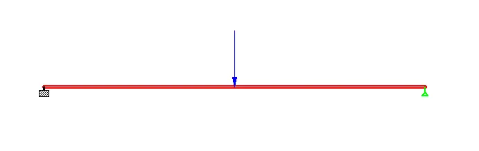
a. A beam of span 16m
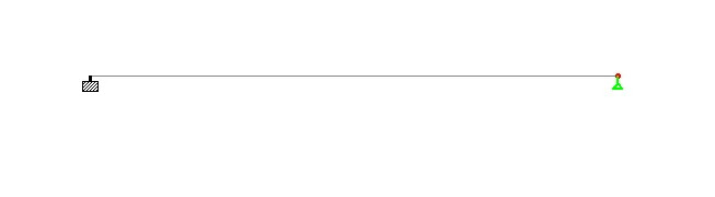
b. Support: Fixed on one end and Roller support (Horizontal) on the other end
c. A point load of 50kN at the mid-point
d. Draw SFD and BMD using software
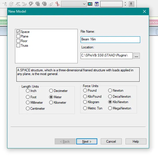
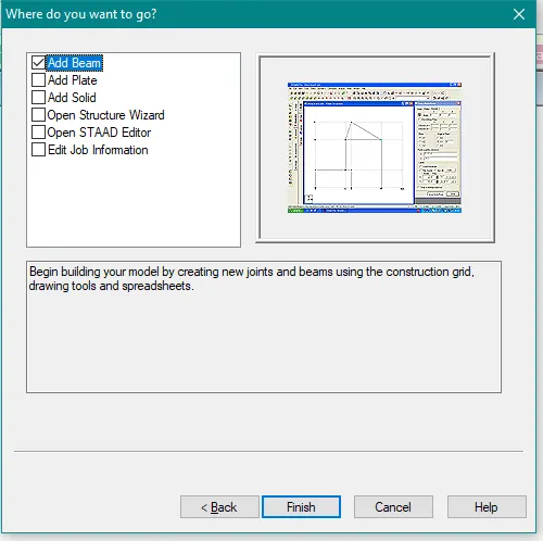
Open STAAD> Create a New Model
Go to geometry and create the first node at X-0, Y-0, and Z-0.
Then, select the node with the node cursor.
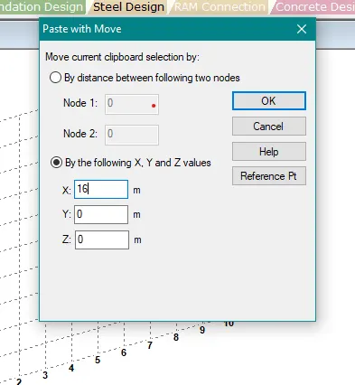
Copy and paste the node at 16 meters in the X-direction
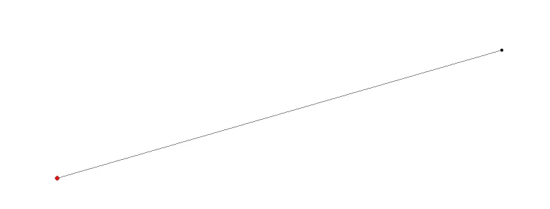
Go to add beam> select first node then second to create a beam of the proposed length.
Beam
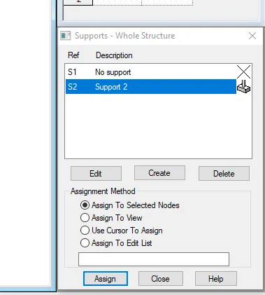
Go to Support> Add> Fixed> Select One Node> Assign To Selected Nodes.
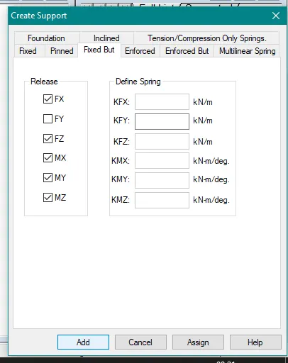
Similarly, create another Support> Fixed But> Release Moments and Horizontal Restraints>
Select The Other Node>Assign to selected.
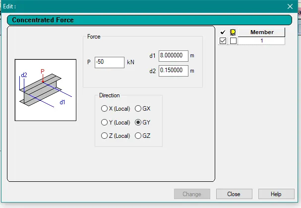
Go to Loads> Create> Member Load> Global Y> -50KN> D1-5, D2-5.
Now, select the load and beam and check the radio button to assign the load.
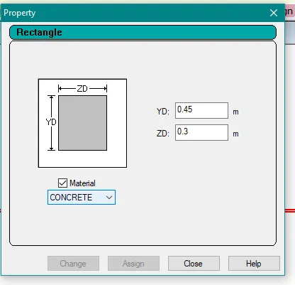
Go to Properties>Define>Concrete Rectangular>Specify Dimensions
Now select the beam and assign the section property.
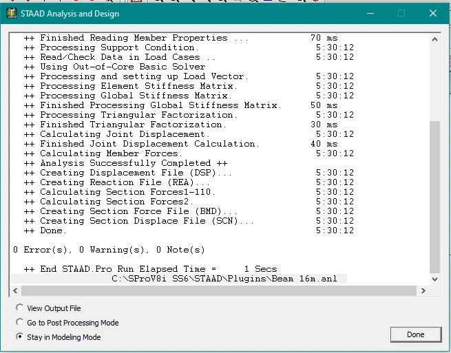
Select the analysis method that is performed analysis from the design and analysis panel.
Run analysis.
RESULTS
Draw SFD and BMD
Go to the Post-Processing Mode>Right click> Structure Diagrams
Then, all the analysis results will be automatically visible on your STAAD screen.
Select Mz for bending moment> Fy for shear force diagram.
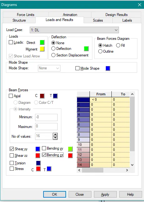
Shear Force Diagram
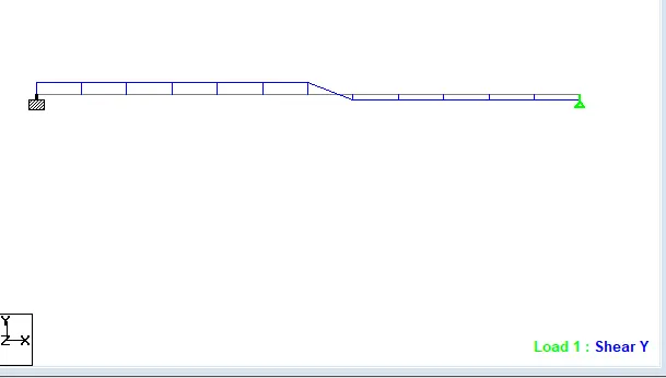
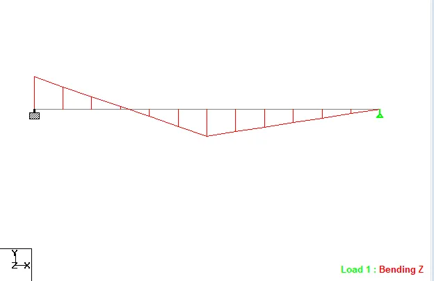
Bending Moment Diagram