Week 1 Challenge
ANS.1
1.1
a.Open Staad pro software in the landing page.
b.Click on share option.
c.Click on send mail.
d.Browse the file we want to share.
e.Click on send mail while ensuring we are signed in.
1.2
Materials that can be designed using STAAD PRO software are as follows :-
a.Aluminium
b.Concrete
c.Steel
d.Stainless steel
1.3
Yes , it is possible to take pictures by using the command utilities.
1.4
Three ways by which we can create a model in STAAD PRO are as follows :-
1. Analytical model
2.Physical model
3.Building model
1.5
Steps followed to assign properties in a model are as follows :-
1. First open property in geometry.
2.Then go to Define material.
3.Then select Rectangle.
4.Mention the dimensions and Material type will be concrete
5.Then assign the property to the material.
ANS.2.
2.1
Six design parameter involved in RCC design are as follows :-
1.Clear cover
2.Compressive strength of concrete
3.Tensile strength of steel
4.Maximum & Minimum diameter of bar
5.Code of practice
6.End concrete design
2.2
The different cursor types available in STAAD Pro are as follows :-
a.Right click and select cursor option are available
b.Node cursor
c.Beam cursor
d.Plate cursor
e.Surface cursor
f.Solid cursor
g.Plate and solid cursor
h.Geometric cursor
i.Physical membrane
2.3
To generate different views for a model , go to view option in the ribbon where we get the options like
Top view
Isometric view
Front view
Left view
Right view
Bottom view
Back view
2.4
First ,go to the support command in the tool pallet command
Then click on create support command
And there we can get option like fixed support, pin support, fixed but , enforced but , cable support, inclined support .
2.5
Five topics that will be included while creating DBR are as follows :-
1.Design Data
2.List of codes
3.Load Parameters
4.Description of Structures and sub-structures
5.List of Drawings
2.6
Multimaterial design is used for 3D model generation, analysis and multi material design for the model.Staad pro supports several steel, concrete and timber material in a separate member.This separate member will coordinate and then formed in to a structure
ANS.3.
3.1
There are four structural system in STAAD PRO software and they are as follows :-
| STRUCTURE SYSTEM LOADING | DEFORM | GEOMETRY | JOINT |
| Space 3D | 3D | 3D | ANY |
| Plane 2D | 2D | 2D | ANY |
| Frame perpendicular to XZ | Perpendicular to XZ | 2D | ANY |
| Truss 3D | 3D | 3D | PINNED |
3.2
There are two coordinate systems adapted in STAAD PRO software and they are :-
a.Global Axis:
Global Axis is fixed in the coordinate system
b.Local Axis:
Local Axis is variable and is used for the orientation of beam with the load variable
3.3
a.DBR has its fullform as Design basis report
b.It is needed to take up a project from the scratch to the end.
c.Also to specify the data, compile the data recieved , analysis and design of structural element
d.It contains the assumption and specification to develop the project.
e.DBR will help to avoid the scope and the creep that can lead to budget overness
f. It generally contains the general column drawing.
g.Also contains the project planning
3.4
The different types of analysis options in STAAD pro are as follows :-
1.Perform imperfection analysis
2.Perform Buckling analysis
3.Perform Pushover analysis
4.Change
5.Perform direct analysis
6.Generate floor spectrum
7.Perfrom Analysis
8.P Delta analysis.
9.Perform Cable analysis.
3.5
FIXED SUPPORT
Fixed supports can resist vertical and horizontal forces as well as a moment. Since they restrain both rotation and translation, they are also known as rigid supports. This means that a structure only needs one fixed support in order to be stable. All three equations of equilibrium can be satisfied.
FIXED BUT CONDITION
The Fixed But support condition is used to allow the user to define which degrees of freedom of a node are free and which are fixed. In this the user is free to assign the desired support condition as Fixed or Free.
PRACTICAL
ANS.
Open Staad pro and go to Geometry then grids then Beam grids
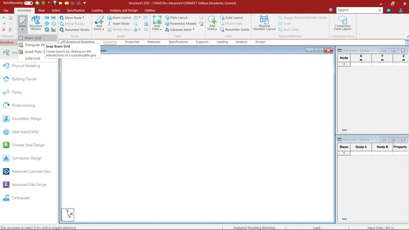
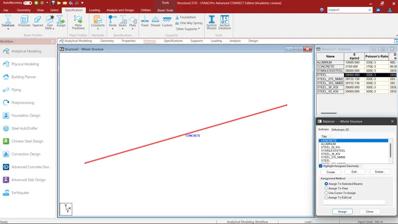
Then assign the material
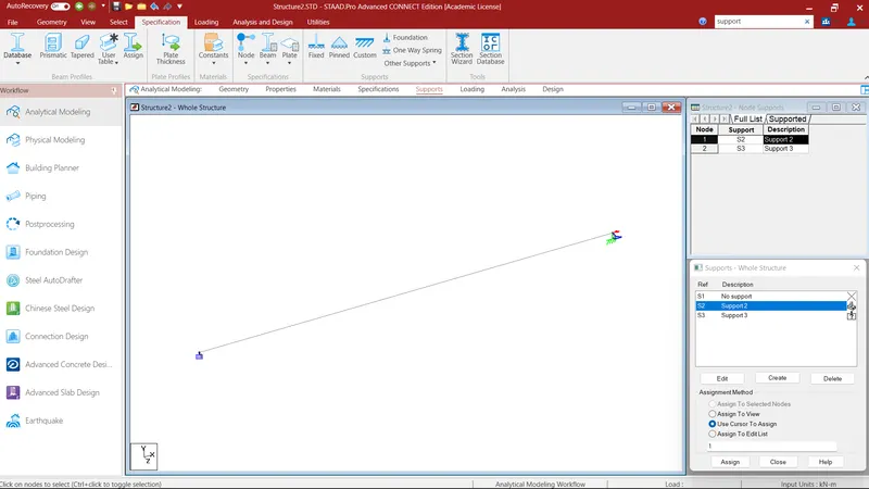
Then go to supports and assign the two supports as one end as Fixed and other as Roller
For roller support, select the Fixed but and realease the Fx and My
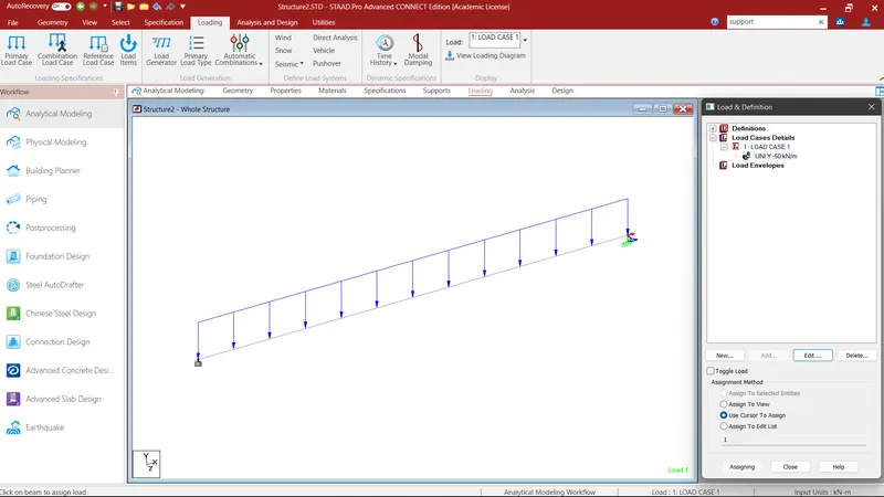
Now assign the load cases as 50Kn point load
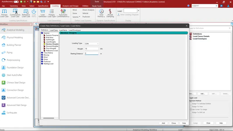
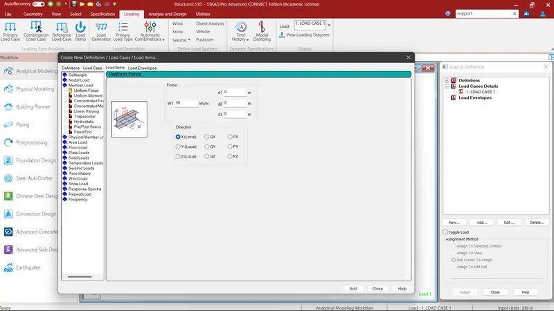
Loads have been assigned
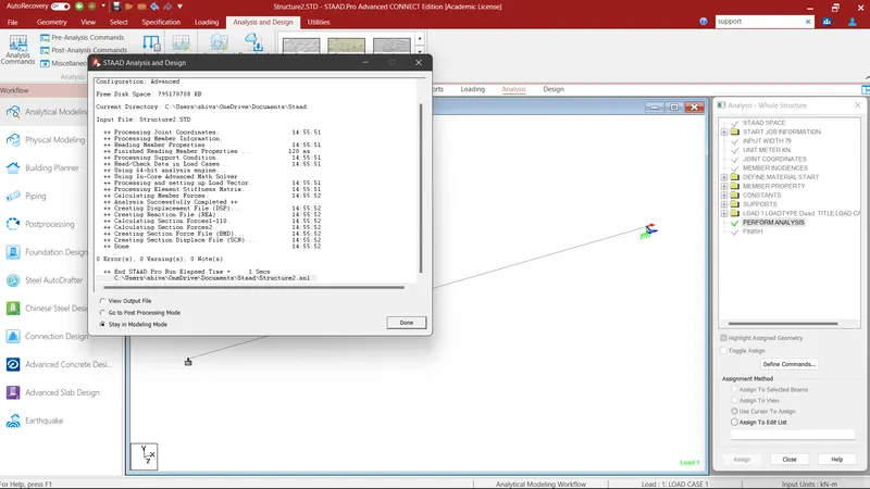
Then run the analysis
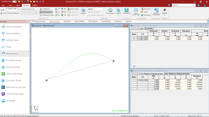
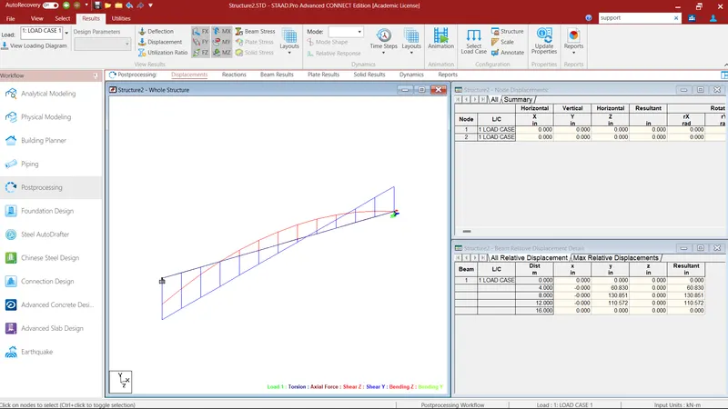
After that Go to post processing mode and select the Applied load case
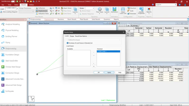
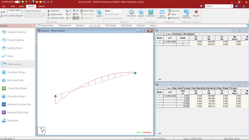
Drawing of SFD and BMD using the software.