Week 1 Challenge
1. Summarize the user interface in TSD with the for the following items: -
ANSWER
Project Workspace – How to access and usage
- To open the new File on TEKLA software.
- Then automatically we get the project workspace and we can access it.
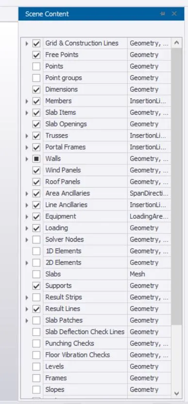
Scene Content – Demonstrate the use of scene content
- we get the project space, on the screen we can able see that scene content at right side.
- It can be used to filter the different components of the model.
Create two scene views
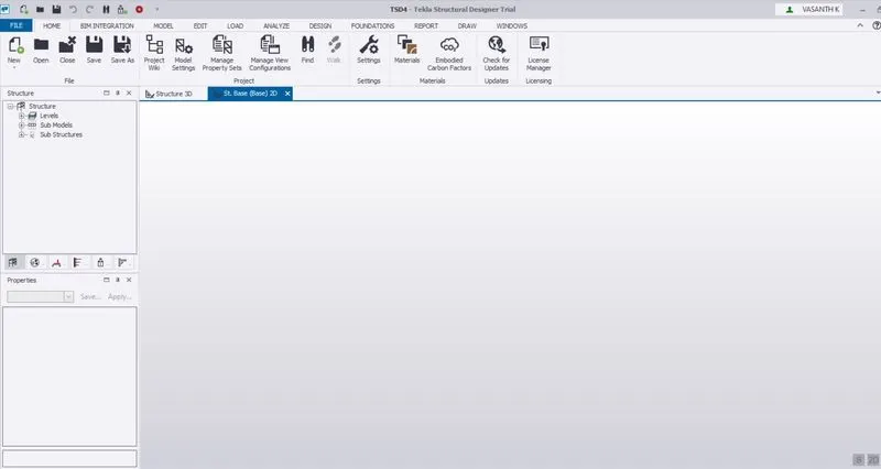
- we create a file, now we can able to see about Base 2D and Structure 3D For top of the tab.
- To obtain 2d view, Click to use.

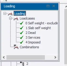
Loading drop list- How to access
- Obviously we get the project interface , for also obtain the loading Drop list.
- It can shows all variety of different loading and combination of loads for applied to the structure.
Properties windows – how to access and usage
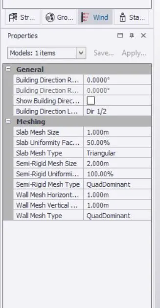
- On project workspace, left side window to show properties about all particulars.
2. Create a new file in TSD and set up the settings for a steel building to have member grade FE410 and concrete grade of M30 as per IS codes. The covers for the members to be as per the following input: -
|
MEMBERS |
IN CONTACT WITH GROUND |
ABOVE GROUND |
|
Column |
50mm |
40mm |
|
Slab |
30mm |
25mm |
|
Pile cap |
75mm |
|
|
Foundation |
50mm |
ANSWER
- After we create a new file.
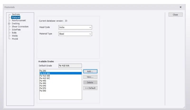
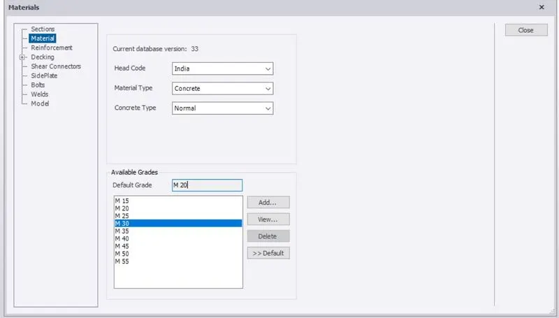
- The main purpose of proccess of design to Add the materials of steel and concrete
- Here we select the materials of Steel is Fe410 and Concrete is M30.
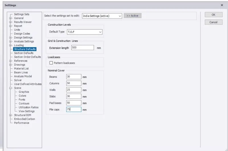
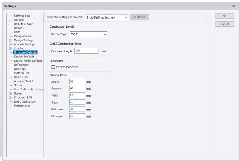
- The same we want change the Nominal cover of components.
- Go to setting > select structure Default > after we change the cover.
Nominal cover of Above ground
Nominal cover of Below the Ground.
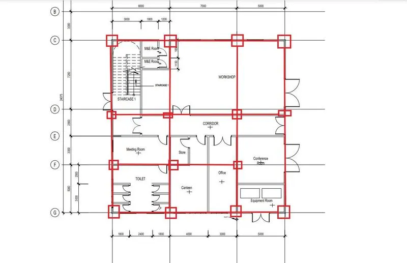
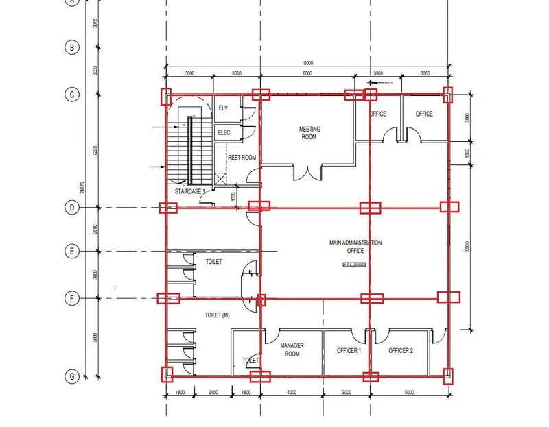
3. With reference to the input drawing as per Attachment 1, 1.1, and 1.2 and study the steel building plan and summarize your understanding of the plan. Based on your study assume and explain the location of columns and beam and develop a hand sketch for each plan.
ANSWER
- For here we need to add the Column and Beam format @ Given layout for analyzing and checking the Grids alignment.
- To provide the column, especially its consider to Symmetric as well uniform alignment, because it will reduce the failure of the structure.
- And also beam providing after checking codes provision of withstanding the failure of the structure.
- here, we provide the column @ all corners and all intersection point along the Grids.
- The main factors of all the beams and columns are connected appropriately.
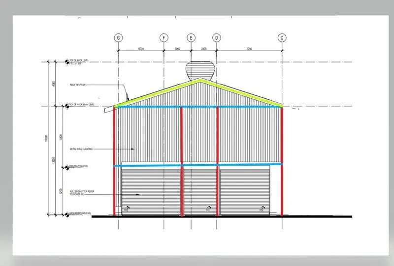
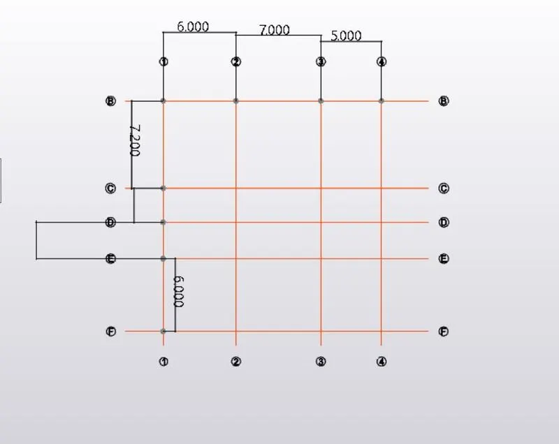
4. Model grid lines and construction levels as per Attachment 1. 1.1 and 1.2. All dimensions are in mm
- The base level to be 500mm below ground level.
ANSWER
- Grids are formed for Given model of attachment 1, 1.1 and 1.2.
- we check the Dimension and choose the Grids
- To draw the primary Grids.
- And the similarly , to draw the Grids for choosing parallel grids option with a proper dimension at Given.
- The same we considered for perpendicular Grids.
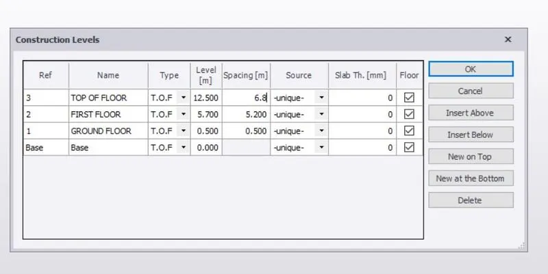
- Go to model > choose construction line > to draw a level of floors.
- Here we take Base to Ground floor level at 500mm.