Usage of Collaborate tool in REVIT
Usage of Collaborate tool in REVIT
1) Open an architectural template. Using the Manage tab set project base point and project shared coordinates for the project.
AIM: To open an architectural template and using the Manage Tab to Set project base point and project shared Co-ordinates for the project.
Introduction: The procedure of how to set project base point and project shared coordinates is explained in detail and the final result is given.
PROCEDURE:
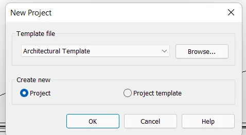
- In the new project dialog box,Select the Architectural template from the drop down list.
- Create new> project>Ok.
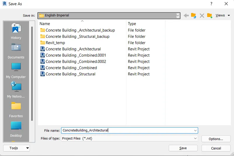
- Click on File tab> Save as option >Project.
- Specify the location where you want to save the file.
- Enter the file name Concrete Building_Architectural>Save.
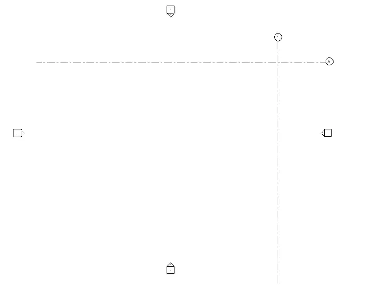
- Go to Architecture tab> Datum panel> Grid.
- Draw a Vertical and Horizontal grid at the extreme right side of the project Screen.
- Rename the Horizontal grid as A-A and vertical grid as 1-1.
- Go to manage tab>Project location panel>Coordinates.
- Select the Specify Coordinates at point from the dropdown list.
- Selct the grid line A-A.
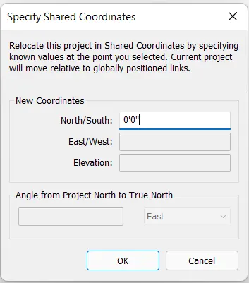
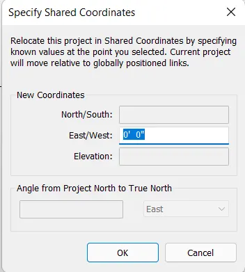
- In the Specify shared Coordinates dialog box, enter North/South Coordinates as 0'0">Ok.
- Again go to project location panel>Coordinates.
- Select the Specify Coordinates at point from the dropdown list.
- Select the grid line 1-1.
- In the Specify shared Coordinates dialog box,Enter East/West Coordinates as 0'0">Ok.
- Save the project file.
- To Set the project base point,Enter VG.
- In the Visibility/Graphics dialog box, Expand Site option and turn on the project base point.
- Click Apply>Ok.
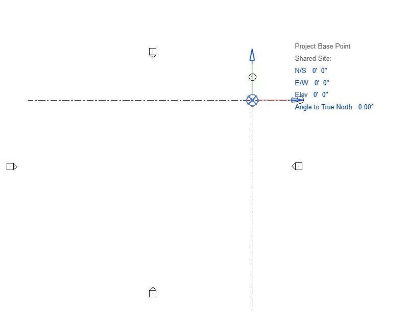
- Move the project base point to previously set project Coordinates.
- When we Click on the project base point icon, the location details are displayed.
- To hide the project base point icon we again go to the Visibility/Graphics dialog box and uncheck the project base point option and click apply>Ok.
RESULT:
The project base point and the project shared Coordinate have been Set using the Manage tab in Revit.
-------------------------------------------------------------------------------------------------------------------------------------------
2) Open another new file but with a structural template. Using the manage tab set project parameters the same as the architectural model. Copy the parameters from the architectural model to the structural template or enter the parameters manually into the structural model.
AIM: To open an Structural template and using the Manage Tab to Set project Parameters same as architectural model.
Introduction: The procedure of how to set project base point and project shared coordinates is explained in detail and the final result is given.
PROCEDURE:
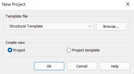
- In the new project dialog box,Select the Structural template from the drop down list.
- Create new> project>Ok.
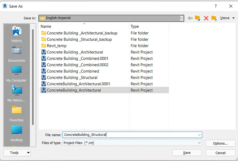
- Click on File tab> Save as option >Project.
- Specify the location where you want to save the file.
- Enter the file name Concrete Building_Structural>Save.
- Go to Architecture tab> Datum panel> Grid.
- Draw a Vertical and Horizontal grid at the extreme right side of the project Screen.
- Rename the Horizontal grid as A-A and vertical grid as 1-1.
- Go to manage tab>Project location panel>Coordinates.
- Select the Specify Coordinates at point from the dropdown list.
- Selct the grid line A-A.
- In the Specify shared Coordinates dialog box, enter North/South Coordinates as 0'0">Ok.
- Again go to project location panel>Coordinates.
- Select the Specify Coordinates at point from the dropdown list.
- Select the grid line 1-1.
- In the Specify shared Coordinates dialog box,Enter East/West Coordinates as 0'0">Ok.
- Save the project file.
- To Set the project base point,Enter VG.
- In the Visibility/Graphics dialog box, Expand Site option and turn on the project base point.
- Click Apply>Ok.
- Move the project base point to previously set project Coordinates.
- When we Click on the project base point icon, the location details are displayed.
- To hide the project base point icon we again go to the Visibility/Graphics dialog box and uncheck the project base point option and click apply>Ok.
RESULT:
The project parameter have been manually set in the Structural model.
-------------------------------------------------------------------------------------------------------------------------------------------
3) Re-open the architectural model. Using the tools under the Collaborate tab make the architectural model a central model (enabling simultaneous working on the model).
AIM: To make architectural model as Central Model.
Introduction: The procedure of how to make the Architectural Model as Central Model is explained in detail and final result is given.
PROCEDURE:
- Select and open the previously created project file ConcreteBuilding_Architectural.
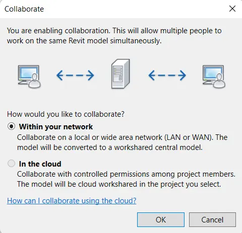
- Go to Collaborate tab> Manage Collaboration panel> Collaborate.
- In the Collaborate dialog Box Select the option within your Network>Ok>Save the File.
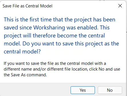
- In the save file as Central Model dialog box,Click Yes.
RESULT:
The Collaboration of the Architectural model is Done and the file is Saved as Central Model.
-------------------------------------------------------------------------------------------------------------------------------------------
4) Create the Grids Longitudinal and Transverse pattern for the project similar to the task done in Week 2.
AIM: To Create the Longitudnal and transverse grid pattern for the project as done in Week 2.
Introduction: The procedure of Create longitudnal and transverse grid pattern is explained in detail and the final result is given.
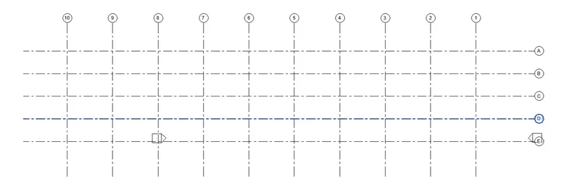
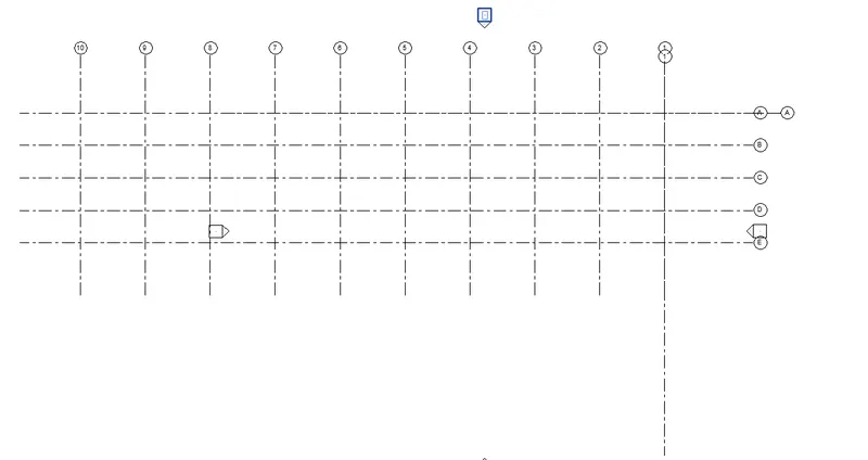
Grids Transverse Grids A,B,C,D,E @ 10' Spacing.
Longitudnal Grids from 1 to 10 @ 20' Spacing.
PROCEDURE:
- Select and open the previously created project file ConcreteBuilding_Architectural.
- Check Create New Local>Open.
- A Local File of the Central Model is Opened.
- Select the Grid 1-1 Created.
- From the Modify Panel Select the Copy Option.
- Specify basepoint and Copy the gridline 9 times towards the left with spacing of 20'.
- Select the Grid A-A Created.
- From the Modify Panel Select the Copy Option.
- Specify the Base Point and copy the grid line 4 times downward with the Spacing of 10'.
RESULT:
The Longitudnal and transverse grid pattern is created similar to that done in Week 2.
-------------------------------------------------------------------------------------------------------------------------------------------
5) Synchronize the changes from the local copy to the central file of the architectural model.
AIM: To Synchronize the changes from the local copy to the central file of the architectural model .
Introduction: The procedure of how to Synchronize the Changes from the local Copy to the Central file of the Architectural Model is explained in detail and the final result is given.
PROCEDURE:
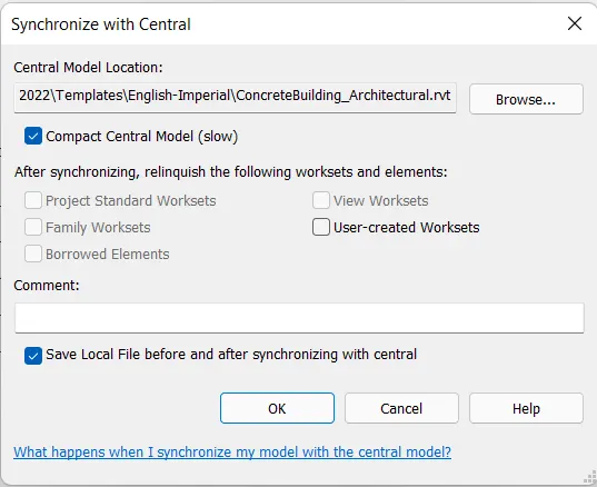
- Go to Collaborate tab >Synchronize panel> Synchronize with Central.
- Select the Synchronize and Modify settings option from the Drop Down list.
- In the Synchronize with Central Dialog box Check the Compact Central model>Ok.
RESULT:
The Local Copy of the Architectural model is Synchronized to the Central File.
-------------------------------------------------------------------------------------------------------------------------------------------
6) Open the structural model and use the collaborate tools to save the model as a central file.
AIM: To open the Structural model and use the Collaborate tools to Save the model as a Central File .
Introduction: The procedure of how to open the Structural model and use the Collaborate tools to Save the model as a Central File is Explained in Detail and the Final Result is given.
PROCEDURE:
- Select and open the previously created project file ConcreteBuilding_Structural.
- Go to Collaborate tab> Manage Collaboration panel> Collaborate.
- In the Collaborate dialog Box Select the option within your Network>Ok>Save the File.
- In the save file as Central Model dialog box,Click Yes.
RESULT:
The Structural model File is Saved as Central File.
-------------------------------------------------------------------------------------------------------------------------------------------
7) Under the Collaborate tab, select the grids and levels from the architectural model, and using Copy Monitor try to copy the grids to the structural model. See what happens when the copy monitored grid is moved around in the structural model.
AIM: To Copy the grids from the Architectural Model to the Structural model Using Copy Moniter Option .
Introduction: The procedure of how to Copy the Grids from the Architectural model to the Structural model using Copy moniter option is Explained in Detail and the Final Result is given.
PROCEDURE:
- Select and open the previously created project file ConcreteBuilding_Structural.
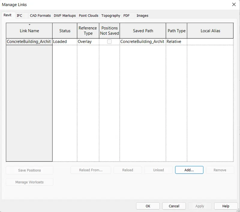
- Go to Manage tab>Manage Links.
- In the Manage Link Dialog box Click on add.
- From the Import dialog Box, Select the Architectural File>Open>Ok.
- Go to Collaborate>Copy Moniter>Select Link.
- Select the Architectural link inserted in the drawing.
- In the Modify Panel Click on Copy Option.
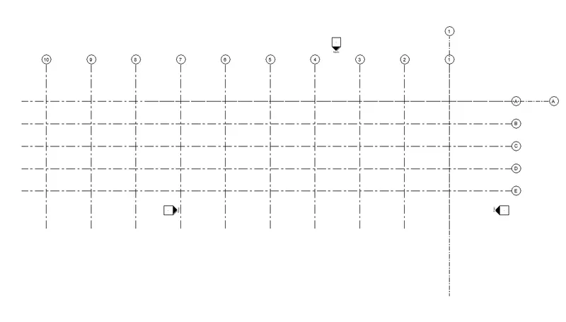
- Select all the Grids linked From the Architectural Model>Finish.
RESULT:
The grids have been Copied to the Structural model .
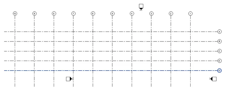
We Can go to Visibility Graphics>Revit Links and Uncheck the Linked File and Click ok , Then we get the Following display of the grids.
-------------------------------------------------------------------------------------------------------------------------------------------
8) Create another new file with a construction template. Save the new file as a central model. This file will include both architectural and structural model. Under the manage tab, Click manage links to link both architectural and structural files. Save the file and close all the files.
AIM: To Create another new file with a Construction template and save the new file as a Central model. Also to link both Structural and Architectural model to the new file.
Introduction: The procedure of how to Create another new file with a Construction template , Save the new file as a central model, and to link both the Structural and architectural model to the new file is explained in detail and the final result is given.
PROCEDURE:
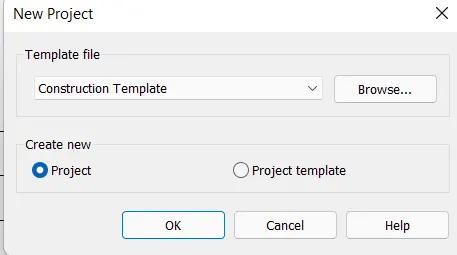
- In the New project dialog box, Select the Construction template from the Drop down list.
- Create>New Project>Ok.
- Next Click on the File Tab.
- Click on Save as Option>Project.
- Specify the Location where you want to save the File.
- Enter File name Building_Combined>Save.
- Go to Collaborate Tab > Manage Collaboration panel> Collaborate.
- In the Collaborate dialog box Select the option Within your Network>Ok.
- Save the File.
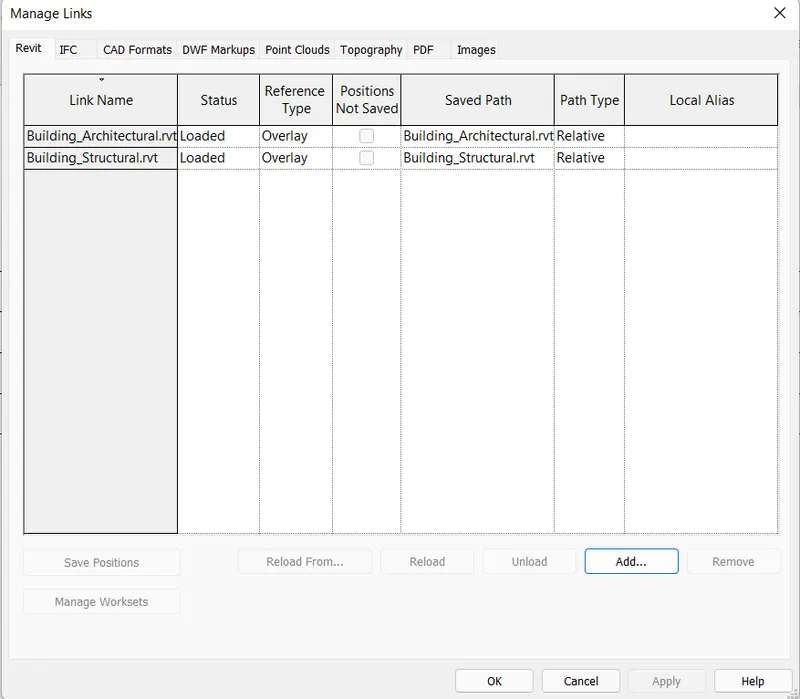
- Go to MAnage tab >Manage Links.
- In the Manage Links Dialog box Click on Add.
- From the Import Dialog Box , Select the Architectural File>Open.
- Similarly Select and add Structural File to the Combined Model.
- In the Manage Link Dialog Box Click ok.
- Save the newly Created File.
RESULT:
The New file has been Created with the Construction template.The File is saved as Central model File,and the Architectural and Structural models have been linked to this new File.
-------------------------------------------------------------------------------------------------------------------------------------------
9) Are the grids from structural and architectural model matching in the construction template created? If yes the model is set up for project 2. If not work on the shared parameters and linking options under Manage links
( Hint: origin to origin, by shared coordinates or by project base point to base point ) to link the models in an appropriate manner.
ANSWER: Yes, the grids from the Structural and architectural models are matching in the Construction template Created.Therefore,the model is set for Project 2.
-------------------------------------------------------------------------------------------------------------------------------------------
10) List a flow chart of a project tree set up in terms of Construction model, Architecture & Structure model, in this exercise and understand how many people can work on the same project using Revit simultaneously.
ANSWER: A Construction Project Comprises of both Structural and Architectural models of the Building.
Construction Model
Architectural Structural
Modelling Doors Modelling Foundation
Modelling Windows Modelling Beam
Modelling Walls Modelling Column
Modelling Openings Modelling Floor
Modelling material Modelling Connections
Modelling StairCase Modelling Roof/Truss.