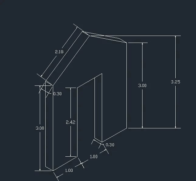
Creating a Floor plan, Footing detail and Isometric view using AutoCad
- AIM: To Create a Floor plan, Footing detail and Isometric view using AutoCad.
Introduction:
Cross Section:
- It is a typical or representative sample ofa larger group.
- It is a surface or shape exposed by making a straight cut through something, especially at right angles to an axis.
- In geometry,a Cross section is the non-empty intersection of a solid body in three-dimensional space with a plane, or the analog in higher-dimensional spaces.
- Cutting an object into slices creates many parallel cross-sections.
Isometric View:
- A 2D isometric view is a flat representation of a 3D isometric projection.
- This method of drawing provides a fast way to create an isometric view of a simple design.
- Distances measured along an isometric axis are correct to scale, but because we are drawing in 2D, we cannot expect to extract other 3D distances and areas, display objects from different viewpoints, or remove hidden lines automatically.
PROCEDURE:
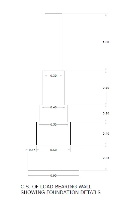
i)
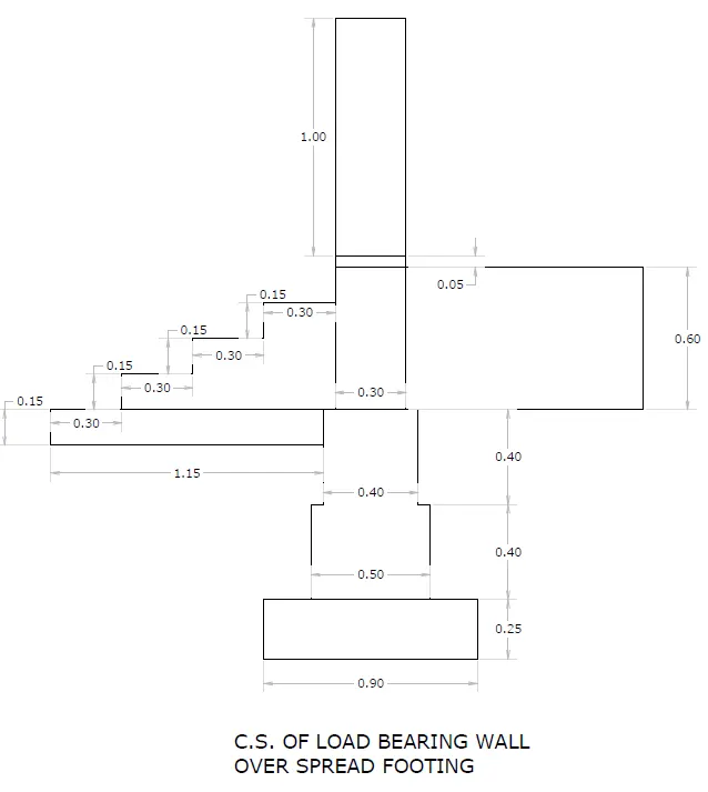
- To open the new sheet and type "U" in command bar to change the units into meters.
- Type "L" to give the line command and to give the dimensions to the command, the line was drawn. Indicate the direction of the line by line keeping ortho is ON.
- To check the all given dimension, then we need to decide the command to draw the perfect diagram.
- Type "C" for close the every particular dimensional objects in a perfect.
- Type "DT" command to write the text at any part of the footing.
- Type "DLI" command for to give the dimensions of each particular part, after finishing the drawing work.
- To save the file, go to the autocad application to choose the save option.
RESULTS:
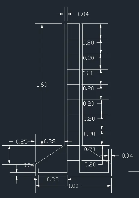
ii)
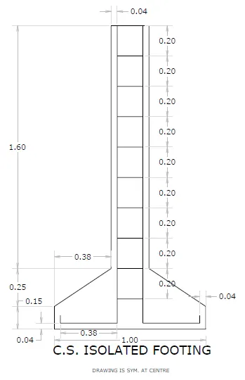
- To open the new sheet and type "U" in command bar to change the units into meters.
- Type "L" to give the line command and to give the dimensions to the command, the line was drawn. Indicate the direction of the line by line keeping ortho is ON.
- Type "O" for the offset command and type the dimension 0.20m, then check inside , where parallel line is required.
- Type "Tr" for trim command, to trim extra lines.
- To check the all given dimension, then we need to decide the command to draw the perfect diagram.
- Type "C" for close the every particular dimensional objects in a perfect.
- Type "DT" command to write the text at any part of the footing.
- Type "DLI" command for to give the dimensions of each particular part, after finishing the drawing work.
- Finally,adopting the above all commands are drawn with dimension with a text.
- The size of the dimensions and the size of the arrows can be changed by typing the "DDIM" in Command bar.
- To save the file, go to the autocad application to choose the save option.
RESULTS:
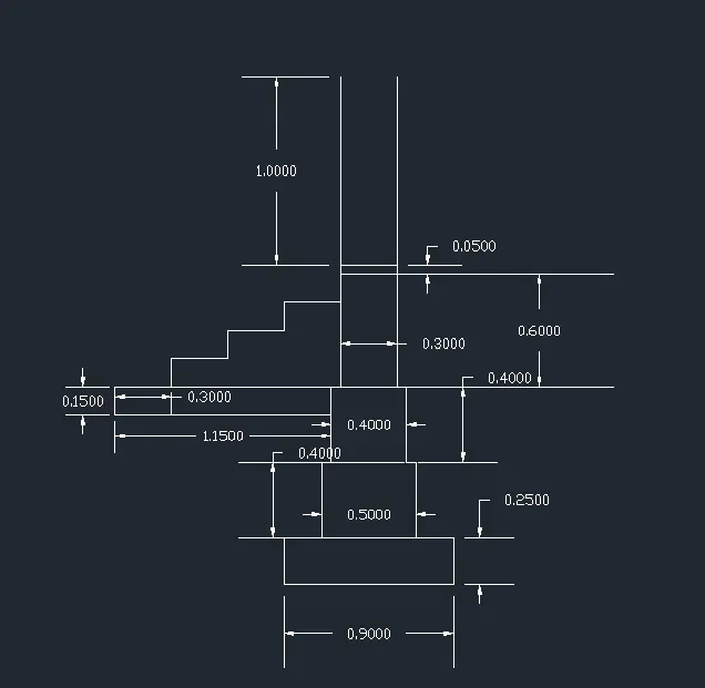
iii)
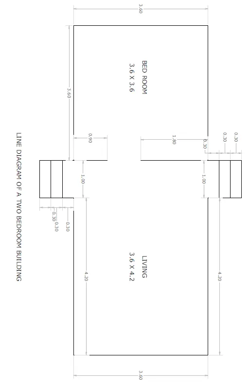
- To open the new sheet and type "U" in command bar to change the units into meters.
- Type "L" to give the line command and to give the dimensions to the command, the line was drawn. Indicate the direction of the line by line keeping ortho is ON.
- Type "O" for the offset command and type the dimension 0.30m, then check inside , where parallel line is required.
- To check the all given dimension, then we need to decide the command to draw the perfect diagram.
- Type "C" for close the every particular dimensional objects in a perfect.
- Type "DT" command to write the text at any part of the footing.
- Type "DLI" command for to give the dimensions of each particular part, after finishing the drawing work.
- Finally,adopting the above all commands are drawn with dimension with a text.
- The size of the dimensions and the size of the arrows can be changed by typing the "DDIM" in Command bar.
- To save the file, go to the autocad application to choose the save option.
RESULTS:
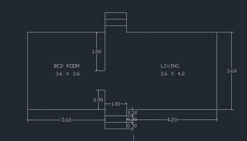
iv)
- To open the new sheet and type "U" in command bar to change the units into meters.
- Type "L" to give the line command and to give the dimensions to the command, the line was drawn. Indicate the direction of the line by line keeping ortho is ON.
- To check the all given dimension, then we need to decide the command to draw the perfect diagram.
- Type "C" for close the every particular dimensional objects in a perfect.
- Type "DT" command to write the text at any part of the footing.
- Type "DLI" command for to give the dimensions of each particular part, after finishing the drawing work.
- Finally,adopting the above all commands are drawn with dimension with a text.
- The size of the dimensions and the size of the arrows can be changed by typing the "DDIM" in Command bar.
- To save the file, go to the autocad application to choose the save option.
RESULTS:
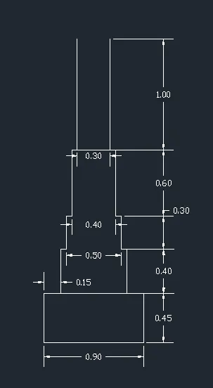
v)
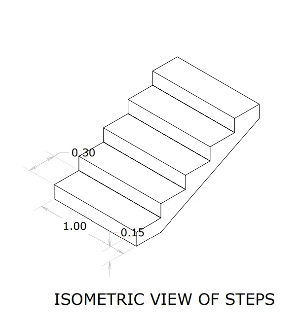
- To open the new sheet and type "U" in command bar to change the units into meters.
- Type "ISOMETRIC" options to change cursor in isometric plane.
- To change the isometric plane 3 options are isoplane right, left , top.
- Type "L" to give the line command and to give the dimensions to the command, the line was drawn. Indicate the direction of the line by line keeping ortho is ON.
- To check the all given dimension, then we need to decide the command to draw the perfect diagram.
- Type "C" for close the every particular dimensional objects in a perfect.
- Type "DT" command to write the text at any part of the footing.
- Type "DLI" command for to give the dimensions of each particular part, after finishing the drawing work.
- Finally,adopting the above all commands are drawn with dimension with a text.
- The size of the dimensions and the size of the arrows can be changed by typing the "DDIM" in Command bar.
- To save the file, go to the autocad application to choose the save option.
RESULTS:
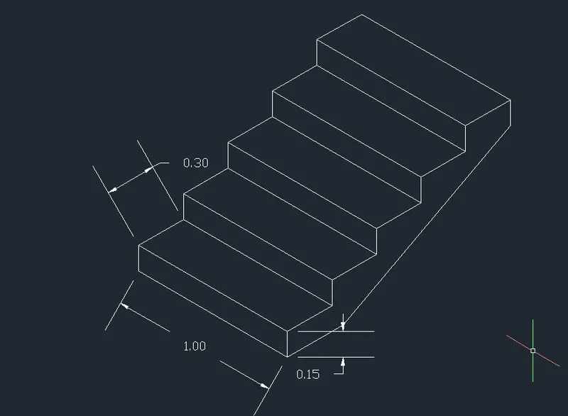
vi)
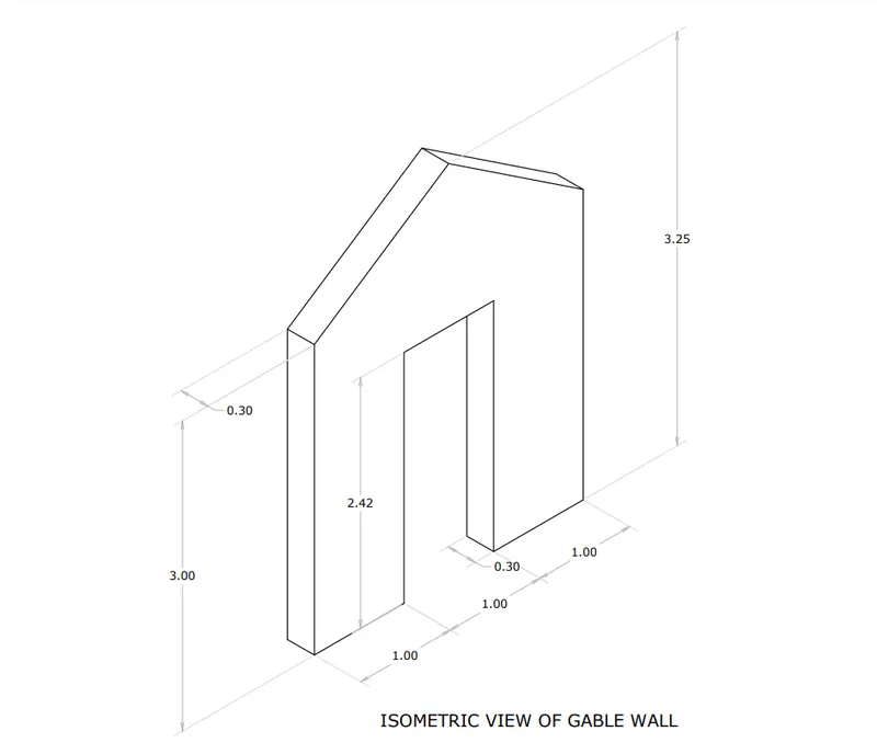
- To open the new sheet and type "U" in command bar to change the units into meters.
- Type "ISOMETRIC" options to change cursor in isometric plane.
- To change the isometric plane 3 options are isoplane right, left , top.
- Type "L" to give the line command and to give the dimensions to the command, the line was drawn. Indicate the direction of the line by line keeping ortho is ON.
- To check the all given dimension, then we need to decide the command to draw the perfect diagram.
- Type "C" for close the every particular dimensional objects in a perfect.
- Type "DT" command to write the text at any part of the footing.
- Type "DLI" command for to give the dimensions of each particular part, after finishing the drawing work.
- Finally,adopting the above all commands are drawn with dimension with a text.
- The size of the dimensions and the size of the arrows can be changed by typing the "DDIM" in Command bar.
- To save the file, go to the autocad application to choose the save option.
RESULTS: