Two-Quadrant Chopper Modelling in Simulink
OBJECTIVE:
1.
- A. To explain the MATLAB demo model named ‘Speed control of a DC motor using BJT H-bridge’.
- B. To comment on the armature current shoot-up from the scope results.
- C. To refer to the help section of ‘The Four-Quadrant Chopper DC Drive (DC7) block’ and compare it with the H-bridge model.
- To develop a 2-quadrant chopper using Simulink & explain the working of the same with the relevant results. (Refer to article – Multi-quadrant operation of motor).
- Explain in a brief about operation of BLDC motor.
SOLUTIONS:
Solution to Objective 1:
A.)
- Important Terminologies involved:
- H-Bridge: It is a circuit that allows voltages to be applied to a load/loads in both forward and backward direction. An H-Bridge is a circuit built to change the direction of the voltage and thus the current flowing to a load/loads.
An H-Bridge is made up of four switches: two in series, and two in parallel, with the load placed in between the switches. In this configuration the circuit takes an “H” shape.

Basic H-Bridge circuit diagram
In the above diagram, ‘M’ represents the DC motor. In order to change the direction of the voltage supplied, the H-Bridge controls the switches that deliver power to the load (S1). Looking at the diagram, if we close S1 and S4 while leaving the rest open, the voltage will be applied from left to right (left connected to positive terminal and right connected to negative terminal) across the motor which will cause the DC Motor to rotate in clockwise direction (forward direction). If S2 and S3 are closed instead and the others open, the voltage will be applied from right to left (left connected to negative terminal and right connected to positive terminal) which will cause the DC Motor to rotate in anti-clockwise direction (backward direction).
- Diode: Any device which freely allows electric current in one direction but does not allow it in the opposite direction is called diode.
A semiconductor diode is basically a p-n junction diode with metallic contacts provided at the ends for the application of an external voltage. It is a 2-terminal device. The symbol for a p-n junction diode is shown below:
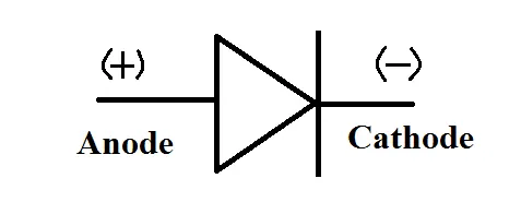
p-n Junction Diode Symbol
- J.T. (Bipolar Junction Transistor): A transistor is obtained by adding another junction to a p-n junction diode. A transistor can control the flow of majority of charge carriers.
It consists of two p-n junction back to back which is obtained by sandwiching either p-type or n-type semiconductor between a pair of opposite type of semiconductors.
It is obtained by sandwiching either p-type or n-type semiconductor between a pair of opposite type of semiconductors. While the central slice is called base, the left and right crystals are called emitter and the collector respectively.
In general there are 2 types of Transistors (Bi-Polar) namely n-p-n transistor and p-n-p type transistor.
- n-p-n transistor consists of thin slice of p-type semiconductor sandwiched between two much thicker n-type semiconductors.
The thin slice of p-type semiconductor is called base. The left hand block of n-type semiconductor is called emitter. The right hand block of n-type semiconductor is called the collector.
The symbol of n-p-n transistor is shown below. The direction of the arrow represents the direction of flow of current. It may be noted that it is opposite to the direction of motion of electrons.

n-p-n Transistor Symbol
- p-n-p transistor consists of a thin slice of a few microns (10-6 m) of n-type semiconductor sandwiched between two much thicker p-type semiconductors.
The thin slice of n-type semiconductor is called the base. The left hand block of p-type semiconductor is called the emitter. The right hand block of p-type semiconductor is called the collector.
Symbol of p-n-p transistor is shown below. The direction of arrow represents the direction of current. It is same as the direction of holes. In p-n-p transistor, the charge carriers are mainly holes.

p-n-p Transisitor Symbol
In the given MATLAB demo model “Speed control of a DC motor using BJT H-bridge”, an H-bridge circuit has been used for controlling the speed/RPM of the DC motor in order to generate the required speed and torque of the DC Motor. This H-bridge Circuit consists of four BJT-diode pairs. For a positive voltage to be applied to the DC motor, the switches Q1 and Q4 are closed and the switches Q2 and Q3 are switched off. The diodes D2-D3 act as free-wheeling diodes when switches Q1 and Q4 are switched off. Similarly for a negative voltage to be applied to the DC motor, the switches Q2 and Q3 are closed and Q1 and Q4 are switched off. The diodes D1-D4 act as free-wheeling diodes when switches Q2 and Q3 are switched off.
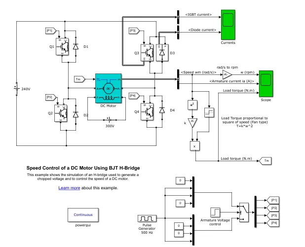
Picture of the "Speed Control of a DC Motor using BJT H-Bridge" Model
For Power-switching applications, BJT operates as IGBT (Insulated Gate Bipolar Transistor) because for such applications, BJT operates in the saturated region and a forward voltage develops between the emitter and collector of the Transistor. Hence IGBT Blocks have been used to model the BJT devices.
The IGBT Blocks doesn’t simulate gate current controlling the IGBT or the BJT. The switches are controlled by a Simulink Signal (1/0).
The DC motor used in the model has a rated power, rated voltage and rated speed of 5 Hp, 24 V, 1750 rpm respectively. The armature voltage of the DC motor can be varied from 0 to 240 Volts when the duty cycle signals fed using the Pulse generator block can be varied from 0% to 100%.
For running/simulating the model, the default duty cycle (Pulse Generator Block) is set to 75% and the mean DC Voltage is set to 180 V.
The Simulation time is set to t=1 second.
On running the model, the motor rotates in the clockwise (forward direction) direction which indicates that a positive voltage has been applied to the DC motor. However at t=0.5 seconds the polarity of the armature voltage of the DC Motor reverses (indicates that now a negative voltage has been applied to the motor) and the motor starts rotating in the counter-clockwise direction and remains in this state till the end of simulation time.
The justification of the above statements can be verified through the following images which shows the simulation results in the form of a plots for various parameters:
Current flowing through IGBT Switch 3(Q3) and Diode 3(D3) of the model
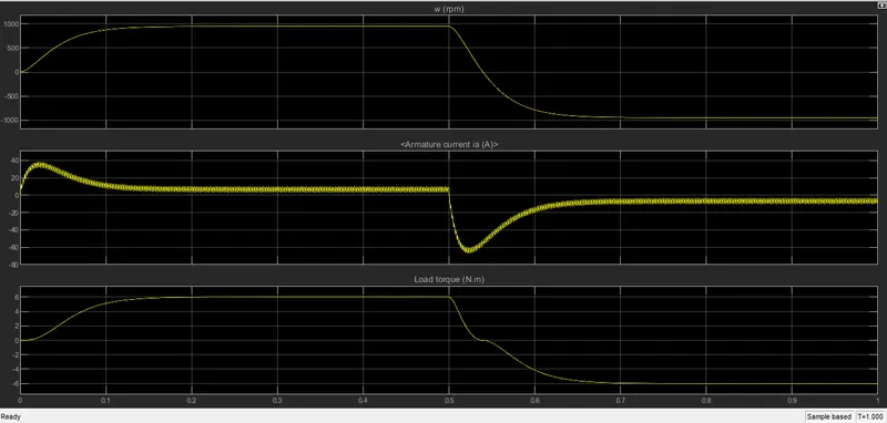
Plots for Load Torque, Armature Current and Rotor Speed for the DC machine obtained after simulation
B.)
Parameters for the DC motor Voltage and the Duty Cycle before running/simulating the model has been given below:
Pulse Width or Duty Cycle for the DC motor: 75%
DC Motor Voltage: 300 Volts
Simulation results for the DC motor obtained:

Current Plot for Pulse Width=75% and the DC Motor Voltage=300 Volts
It can be seen that on reversing the polarity of the applied voltage, the armature current direction changes and its magnitude shoots up drastically. This sudden drastic shoot-up of armature current can be extremely hazardous due to the huge amount of heat generated due to this huge current build-up.
When the motor was running normally and steadily, the applied voltage to the DC motor is opposed by the resistive armature voltage and the induced emf which gets generated due to the rotation of the rotor or due to the armature windings through the local magnetic field.
When the polarity of the applied DC Voltage is reversed suddenly, the armature current in the DC motor also reverses suddenly and the induced emf which was previously opposing the applied voltage, now aids the current flow instead of opposing it, hence the big surge in current.
This sudden current surge can be rectified/controlled by bringing suitable changes to the DC motor voltage and/or to the duty cycle.
However according to the simulation results, there isn’t any significant drop in the current surge when the DC Motor Voltage is increased. In order to bring about a significant decrease in the current surge on the basis of DC Motor Voltage only, we have to consequently increase the DC motor voltage to a very high value, which gets somewhat difficult practically.

Armature Current Plot for Applied Voltage=1000 Volts and Pulse Width=75%
However decreasing the duty cycle has shown a significant impact on decreasing the current surge when the polarity of the DC motor is reversed. The simulation results (in the form of plots) for various duty cycles are shown below:

Armature Current Plot for Applied Voltage=300 Volts and Pulse Width=60%

Armature Current Plot for Applied Voltage=300 Volts and Pulse Width=45%

Armature Current Plot for Applied Voltage=300 Volts and Pulse Width=30%
C.)
The Differences between the 4-quadrant DC(DC7) Motor Drive and BJT H-Bridge DC motor Drive are as follows:
BJT DC Motor Model
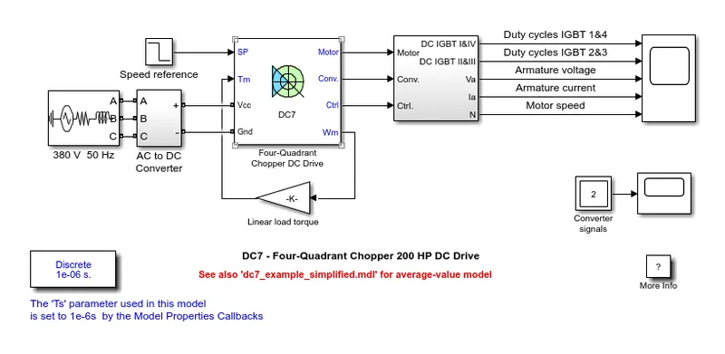
4-Quadrant DC Motor Drive
|
4-Quadrant DC(DC7) Motor Drive |
BJT H-Bridge DC Motor Drive |
|
As the name suggests, the 4-Quadrant DC(DC7) Motor Drive can operate in all 4 quadrants i.e. -> Forward Motoring, Reverse Motoring, Reverse Braking and Forward Braking zones. |
The BJT H-Bridge DC Motor Drive used for controlling the torque and speed of the DC motor, although having 4 switches, operates in 2 quadrants ->Forward Motoring zone and Reverse Motoring zone as seen from the plots obtained after simulation. |
|
Separate duty cycles for each mode of operation gives the motor more versatility in terms of torque and power output range. |
Only a single duty cycle at a time is fed to the motor. Hence the range of Torque and Power output is less compared to the 4-Quadrant DC Motor Drive. |
|
To prevent the overshoot/surge of armature current on reversing the polarity of the applied voltage, there is speed regulator and current regulator. The speed reference change rate follows acceleration and deceleration ramps in order to avoid sudden reference changes that could cause armature over-current and destabilize the system. |
There is no in-built system to prevent the sudden surge of current when the polarity of the applied voltage is reversed. If suitable changes are not applied to the duty cycle and/or the applied voltage, then there is a high chance of a fire hazard which occurs due to the extreme amount of heat due to the sudden current shoot-up. |
Solution to Objective 2:
Two-Quadrant Chopper: This is a type of chopper circuit where the average voltage always remains positive but the average load current may be positive or negative. A 2-quadrant Chopper circuit diagram is shown below:
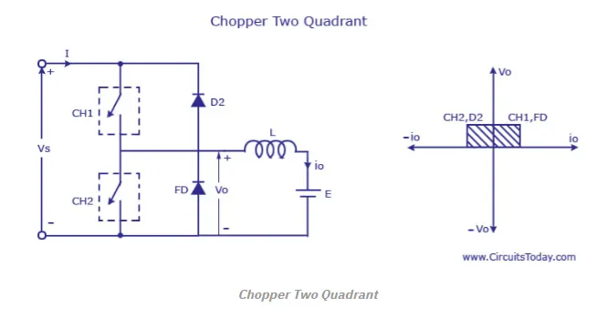
2-Quadrant Chopper Circuit Diagram
The output voltage will always be positive as the Diode FD in the diagram is connected across the load. When the switch CH1 is turned on, it can be said that the chopper is on freewheeling Diode (FD) starts conducting and the output Vo=Vs. The direction of the current flowing through the load is reversed. The current i0 will be flowing towards the source and it will be positive regardless the chopper is on or the FD conducts. The load current will be negative if the chopper is or the diode D2 conducts.
It should be noted that the two choppers should not be turned on simultaneously as the combined action of current flowing through both the choppers may result in a short circuit in the supply lines.
The average voltage will be always positive but the average load current might be positive or negative
This type of chopper configuration is generally used for regenerative braking and motoring.
Modelling of 2-Quadrant Chopper using Simulink:
For modelling my 2-Quadrant Chopper circuit, I have used the Pulse Generator block to feed the Duty Cycle into the model. The pulse width or the Duty Cycle has been set to 50%. I have used two MOSFET blocks as choppers (switches) and a DC Machine has been used as load. The DC machine voltage has been set to 120 V and the applied Voltage to the circuit has been set to 240 Volts. The pulse amplitude has been set to 10 Volts. The picture of my model has been attached below:
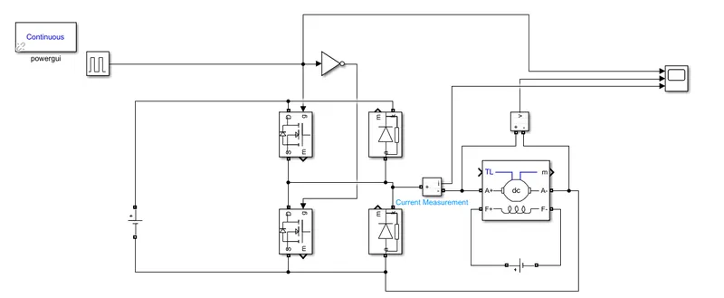
My 2-Quadrant Chopper Circuit
The output plots after simulation are shown below:
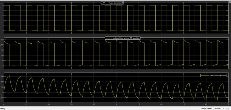
Plots obtained for the Voltage Drop across he Dc Machine and the Current flowing across the DC machine
The Voltage across the DC machine is always positive. However it can be seen that that current is in the positive region as well as in the negative region.
Solution to Objective 3:
Brushless DC Motor: In the last 25 years, DC Motors have been developed by combining a small motor much like a permanent magnetic stepper motor with a rotor position sensor and a solid-state electronic switching circuit. These motors are called brushless DC motors because they run from a DC Power source but don’t have commutators and brushes. The rotor of a brushless DC motor is similar to a permanent magnet stepper motor, except that it is non-salient. The stator can have 3 or more phases.
The basic components of a Brushless DC motor are:
- A permanent magnet rotor.
- A stator with a three-, four- or more phase winding.
- A rotor position sensor.
- An electronic circuit to control the phases of the rotor winding.
A brushless DC motor functions by energizing one stator coil at a time with a constant DC voltage. When a coil is turned on, it produces a stator magnetic field Bs and a torque is produced on the rotor is given by:
τind = k*Br X Bs
The torque tends to align with the stator magnetic field.
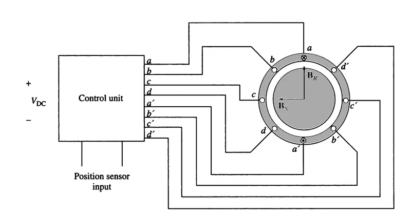
A Brushless DC Motor and it's associated Control Unit. The inputs to the control unit consist of a DC Power Source and a signal proportional to the current Rotor Position
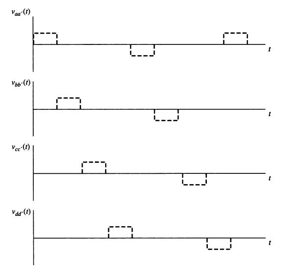
The Voltages applied to the Stator Coils
If coil ‘a’ remains energized all the time, the rotor would turn until the 2 magnetic fields were aligned, and then it would stop, just like the stepper motor. The key to operation of a brushless DC motor is that includes a position sensor, so that the control circuit will know when the rotor is almost aligned with the stator magnetic field. At that time coil ‘a’ will be turned off and coil ‘b’ will be turned on causing the rotor to again experience a counterclockwise torque, and to continue rotating. This process continues indefinitely with the coils turned on in the order a, b, c, d,-a,-b,-c,-d,…. So that the motor turns continuously.
The electronics of the control circuit can be used to control both the speed and the direction of the motor.
Thus the net effect of this design is a motor that runs from a DC power source, with full control over the speed and direction of rotation.
REFERENCES: