Tuning a compensator using a Bode plot graphical Tuning
AIM: To use bode diagram to tune a compensator for DC motor, explain some terms and explain S- plane
OBJECTIVE:
1. a.) Explain the following terms and note down their mathematical formulae.
- Rise time
- Settling time
- Peak overshoot
- Steady-state error
b.) Tune a compensator for DC Motor Using Bode Diagram Graphical Tuning. The transfer function is given as-
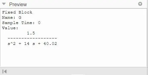
`G = (1.5)/(s^2 +14s +40.02`
Meet the following specifications - Rise time less than 0.5 seconds, Steady-state error of less than 5%, Overshoot of less than 10%, Gain margin greater than 20 dB, Phase margin greater than 40 degrees.
2. Can a system with a pole on the right half of the s-plane be stable? Justify your answer with an example.
3. Use the following link of Synchronous Buck Converter to solve the following questions:
a.) Simulate the default values and comment on the results concerning the stability of the system.
b.) Change the reference voltage and comment on whether it is tracking the reference voltage or not.
c.) Change the PI gain values and comment on the stability of the system w.r.t. new values.
d.) Change the switching frequency and comment on the stability of the system w.r.t. new values.
OBJECTIVE 1 -
a.) Explain the following terms and note down their mathematical formulae.
- Rise time
- Settling time
- Peak overshoot
- Steady-state error
1. Rise time
Rise time is defined as the time for the waveform to go from o.1 to 0.9 of its final value. Rise time is found for the difference in time at c(t) = 0.9 and c(t) = 0.1
`:. t_r = (pi - θ)/ω_d`
2. Settling Time
Settling Time is the time required for the response to reach the steady-state and stay within the specified tolerance bands around the final value. In general, the tolerance bands are 2% and 5%. The settling time is denoted as ().
The settling time for the 5% tolerance band is:
`:. t_s = 3 / ( δ . ω_n) = 3r`
The settling time for the 2% tolerance band is:
`:. t_s = 4 / ( δ . ω_n) = 4r`
3. Peak Overshoot
Peak Time is the time required for the response to reach peak value for the first time. It is denoted by (tp">tptp). At t=tp">t=tpt=tp the first derivative of the response is zero.
`:. t_p = pi/ ω_d`
Peak Overshoot (M_p) is defined as the deviation of the response at the peak time from the final value of the response it is also called the maximum overshoot. We can write it as
`:. M_p = c(t_p) - c( ∞)`
4. Steady-State Error
A Steady-State error is defined as the difference between the desired value and the actual value of a system when the response has reached the steady state. We can calculate the steady-state error of the system using a final value theorem.
`:. e_ ∞ = lim_( t->0) e(t) = lim_(s-> 0) E(s) = lim s/(1+G(s)) R(s)`
b)Tune a compensator for DC Motor Using Bode Diagram Graphical Tuning. The transfer function is given as-
`G = (1.5)/(s^2 +14s +40.02`
Meet the following specifications - Rise time less than 0.5 seconds, Steady-state error of less than 5%, Overshoot of less than 10%, Gain margin greater than 20 dB, Phase margin greater than 40 degrees.
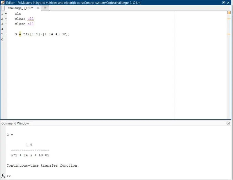
By seeing the transfer function, one can understand it is a second-order LTI system. The Poles and zeros determine the characteristics of the system. To find poles of the system, the roots of the characteristic equation must be equated to zero.
`s^2 + 14s + 40.02 =0`
`(s + 10)(s + 4) = 0`
`s = - 10, s = - 4`
The poles are at -10 and -4 on the left side of the s-plane. There is no Zero, The system is a stable second-order system.
Open the Control System Designer window for the defined transfer function by using the control system designer command.
The Control system designer window displays the BODE plot editor and Root locus editor alongside Step response. One must tune the compensator to satisfy the condition of design requirements.
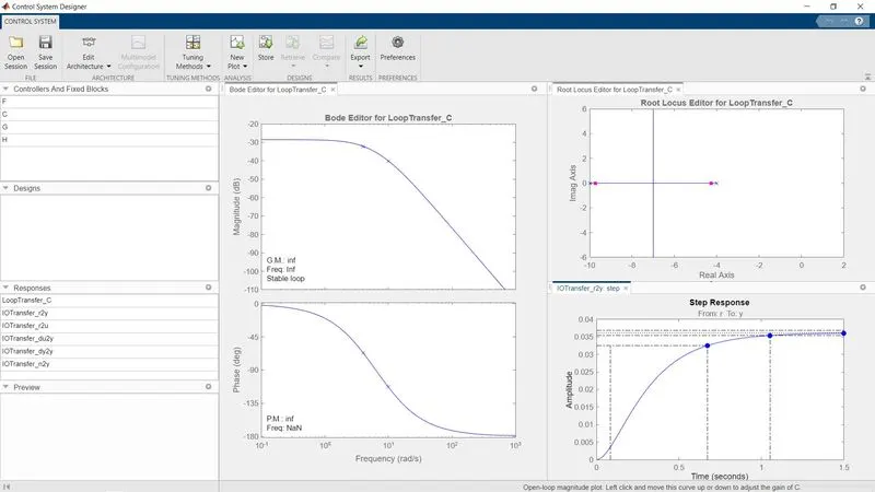
- To achieve rise time < 0.5sec and overshoot < 10%, the Proportional gain (Kp) is adjusted at first.
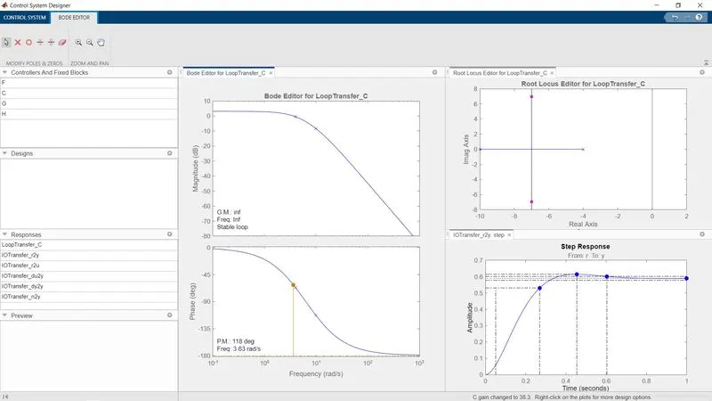
- Kp can be thought of as the powerful motor, powerful battery & ultracapacitor to achieve peak acceleration, top speed, and high power density-related parameters. However, adjusting just the gain doesn't allow to achieve steady-state error < 5% as the step response can get to a maximum of about 0.8, whereas at least 0.95 is needed to satisfy conditions. So although increasing Kp allows reducing rise time and overshoot, it is insufficient to meet other conditions
- The Rise time and Overshoot have got satisfied now. To achieve 5% of steady-state error, the integrator must get added by right-clicking the Magnitude plot of the Bode plot editor as shown below.
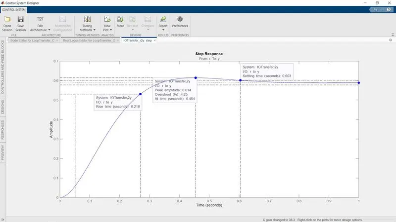
- This is where an Integral controller (Ki) comes in. Ki can be thought of as the optimizer which will allow the use of the power sources as effectively as possible to achieve high energy density along with high power density to achieve final output. Adding an integrator eliminates the steady-state error and the step response converges at 1. However, at this point, while every other condition is met, the rise time goes beyond 0.5 seconds.
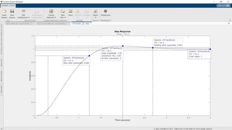
- This is where a lead compensator comes in.
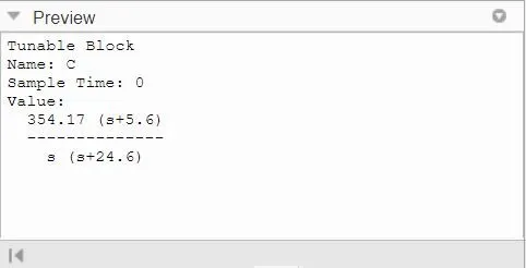
- A lead compensator is a combination of a pole and zeroes added to the already existing poles and zeroes. Although this procedure involves trial and error for the placements of the pole and zero, the point is to make the added pole a larger negative number than the added zero to shift the entire root locus to the left, as that improves the stability and the system's response speed (i.e. rise time).
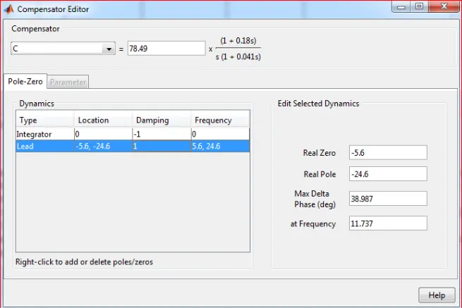
- There isn't just one combination that works here, but placing the zero at -5.6 and the pole at -24.6 was enough to meet all the requirements, as can be seen in the figure below.
- A 'Proportional-Integral' or 'PI' controller was used here along with a phase lead compensator to meet the requirements. The 'D' or 'Derivative' controller, part of 'PID', was unnecessary here since no fluctuations or vibrations needed damping effects.
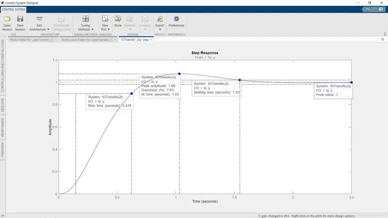
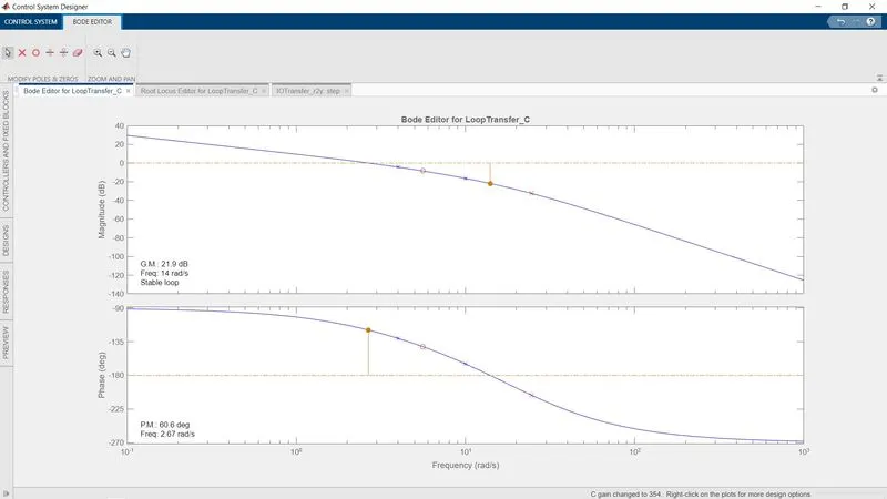
hence all the required specifications for tunning of PID have been met.
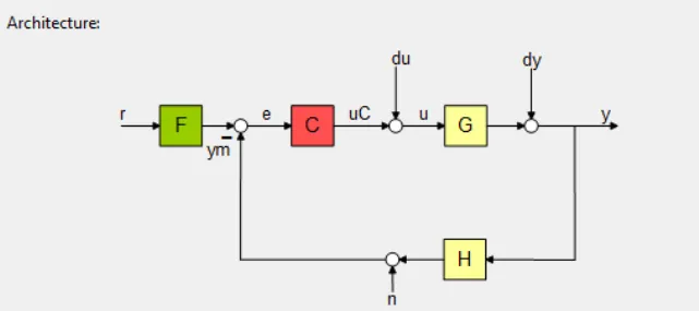
- This is typically how the closed-loop feedback system for this kind of problem would look like. As is seen below, the 'C' or the 'Compensator' block has an added integrator along with a lead compensator (pole and zero) that can be fed to the plant function 'G'
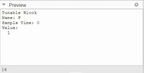
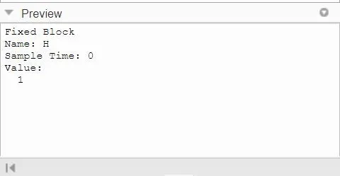
- As the steady-state error was eliminated by the addition of an integrator, the value of F and H are identical as there is no difference between the input 'r' and the output 'y'
OBJECTIVE 2. Can a system with a pole on the right half of the s-plane be stable? Justify your answer with an example.
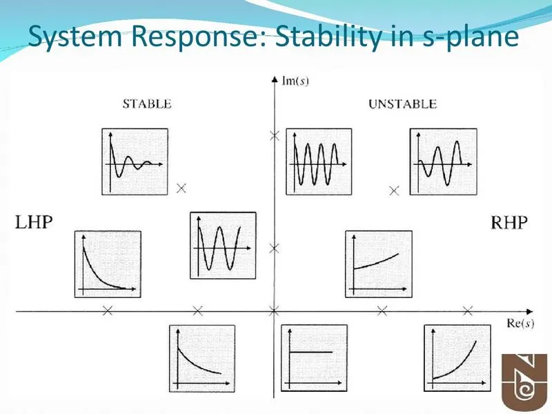
- From the above image, we can see that poles in the right half of the S plane are unstable.
- A system is said to be stable if for bounded input there exists the bounded output.
- The stability of a linear system may be determined directly from its transfer function. A nthorder linear system is asymptotically stable only if all of the components in the homogeneous response from a finite set of initial conditions decay to zero as time increases, or
`lim_(t->oo) sum_(i=1)^n C_ie^(PI^t) =0`
Where the PI is the system poles. In a stable system, all components of the homogeneous response must decay to zero as time increases. If any pole has a positive real part there is a component in the output that increases without bound, causing the system to be unstable.
For a linear system to be stable, all of its poles must have negative real parts that are they must all lie within the left half of the s-plane. An “unstable” pole, lying in the right half of the s-plane, generates a component in the system homogeneous response that increases without bound from any finite initial conditions. A system having one or more poles lying on the imaginary axis of the s-plane has non-decaying oscillatory components in its homogeneous response and is defined to be marginally stable.
Stability: The total response of a system is the sum of the forced and natural responses:
`c(t) = c_(f or ce^(t)) +c_(natural) (t)`
A linear, time-invariant system is stable if the natural response approached zero as the time approaches infinity.
- A linear, time-invariant system is unstable is the natural response grows without bound as the time approaches infinity.
- A linear, time-invariant system is marginally stable if the natural response neither decays nor grow, but remains constant or oscillates as time approaches infinity
By looking at the placement of the poles of a system in the s-plane we can conclude the stability of a system.
- If the poles of the closed-loop are in the left half of the s-plane (negative and real), the system is stable.
- If the poles of the closed loop are in the right half of the s-place (positive and real), the system is unstable.
- If the poles appear on the imaginary axis and none appear in the Right-Hand Plane, the system is marginally stable.
OBJECTIVE 3 -
3. Use the following link of Synchronous Buck Converter in order to solve the following questions:
a.) Run the simulation for the default values and comment on the results with respect to the stability of the system.
b.) Change the reference voltage and comment on whether it is tracking the reference voltage or not.
c.) Change the PI gain values and comment on the stability of the system w.r.t. new values.
d.) Change the switching frequency and comment on the stability of the system w.r.t.
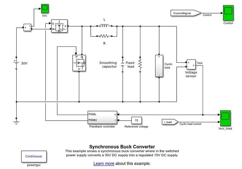
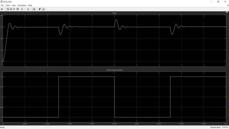
a. Run the simulation for the default values and comment on the results with respect to the stability of the system.
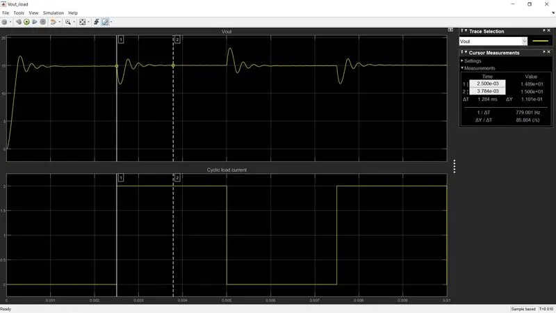
- The output voltage is bounded and stabilizes at 15V, hence the system is stable.
b) Change the reference voltage and comment on whether it is tracking the reference voltage or not.
Change reference voltage from 15V to 5V
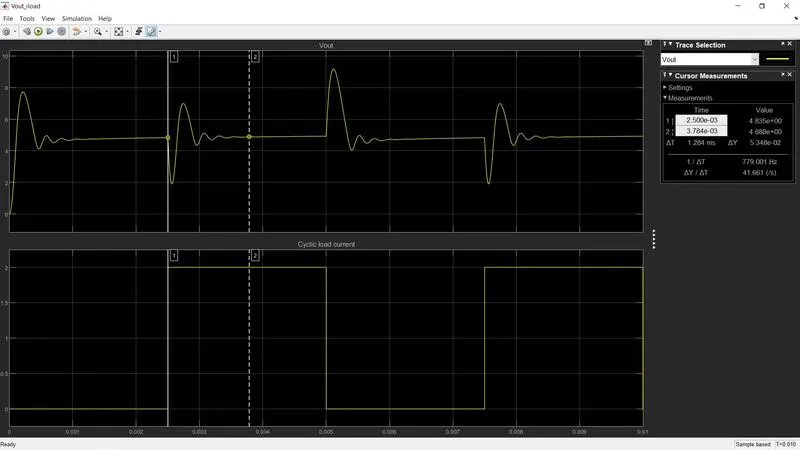
- The reference voltage is being tracked as is evident. A cyclic load has been applied which is why the output is repetitive. It constantly stabilizes at the reference voltage before repeating the entire cycle again.
Change reference voltage from 15V to 25V
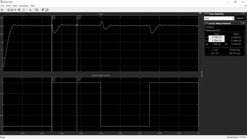
- Reference voltage is tracked here as well as the system stabilizes at 25V constantly.
- The ability of the system to track the reference voltage is seen through these changes. This is made possible due to the feedback control system and the PID controller, which constantly adjusts the system to meet the requirements of the reference given.
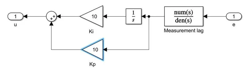
c) Change the PI gain values and comment on the stability of the system w.r.t. new values.
1) Kp - 0.5, Ki - 200 (DEFAULT)
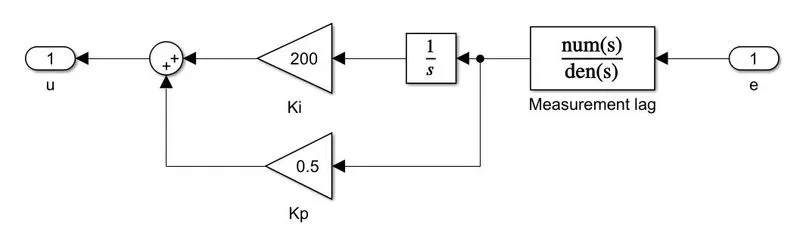
2) Kp =1 , Ki = 1
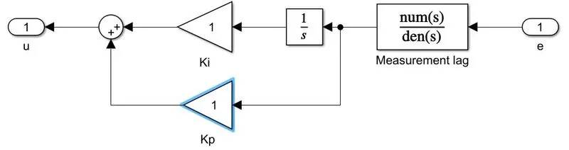
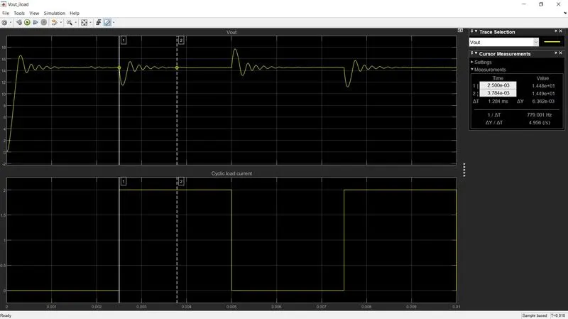
3) kp = 10 , ki = 10
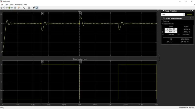
4) Kp = 0.01 , Ki = 200
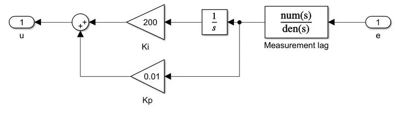
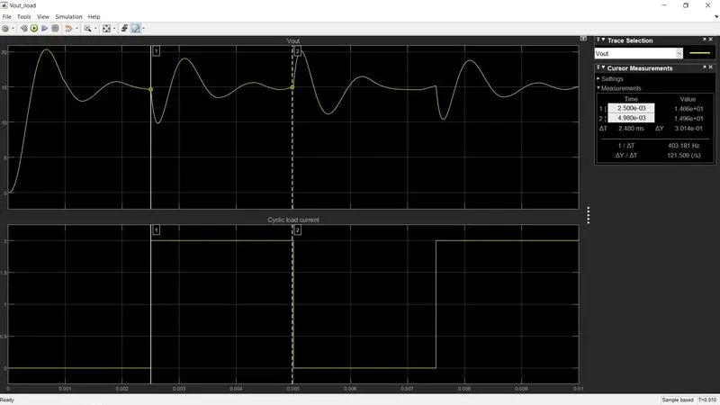
- It can be concluded from the above graphs that a balance between Kp and Ki is crucial. Insufficient Ki will lead to larger steady-state error as is seen in Graph 2, so that is undesirable.
- If Ki is good enough but Kp is too low, that will lead to huge rise time, overshoot, and settling time with too many fluctuations and thus an unstable system.
- Graph 1 is the most stable system while Graph 4 is the least stable.
d.) Change the switching frequency and comment on the stability of the system w.r.t. new values.
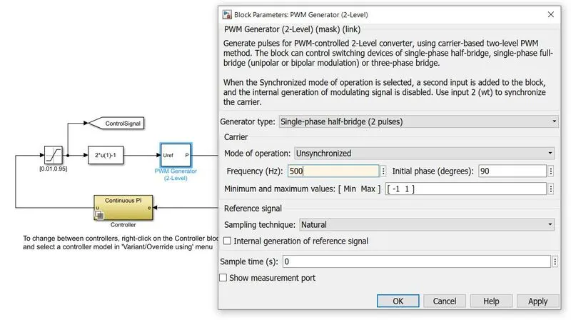
500 Hz
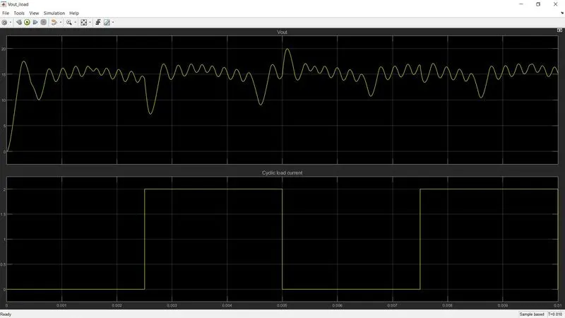
10,000 Hz
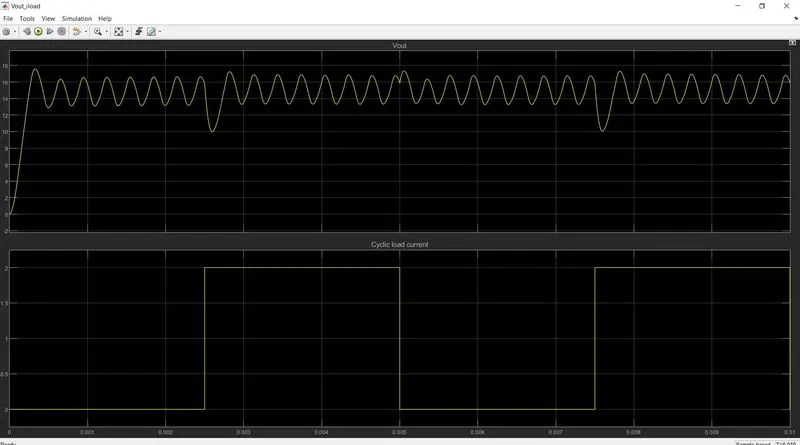
2,50,000 Hz
- Switching frequency refers to the number of times the switch changes state (on/off) per second. As the switching frequency increases, fluctuations in the output are reduced, as is evident. Settling time is much longer with lower switching frequencies, and due to higher voltage ripples, the stability of the system is lower.
- With higher switching frequency, smaller inductors and capacitors are needed as well, and a better dynamic performance can be achieved.
- However, due to higher switching losses (which are the main losses in power converters), efficiency is reduced as more power is lost in the form of heat.
Conclusion:-
- we got some knowledge about the following time-dependent terms like rising time, settling time, etc.
- We have to tune the Transfer Function and by introducing an integrator to the circuit and adjusting the rise time and many functions to attend to the requirement.
- It is never been possible to make a system completely stable if any one pole of the system is on the right side of the plane.
- Marginally stable as the oscillation is not been cleared and jumps within the 1V of error
- Marginally stable as the oscillation is not been cleared and jumps within the 1V of error and is more stable than the above discreet time-variant PI
- stable system the oscillation is been stopped and the required voltage is been achieved
- stable system the oscillation is been stopped and the required voltage is been achieved,it has two parts.
- The system is stable, On changing the frequency I got to reduce the Peak Overshoot of the system and changing the linear switching to smooth switching.