To plan a structural layout and to create grids using TSD
Aim:- To plan a structural layout and to create grids using TSD. Also to understand basic usage about the software.
Introduction:- To thoroughly study the usage of various commands in the software, basic space, appearance, settings, tabs in the software. To study the purpose of the software and creating a new file in the TSD.
Procedure:-
Ans 1.
- Project Workspace – How to access and usage
When we open TSD we can see a basic screen with some tools in it. Project workspace is a space where we can see the project related things. Project workspace is located to the left of the screen below the basic icons and tabs. There we can see the structure and levels in the structure, architectural grids, frames that are added in the model, sub-models, and the sub structures. We can find the members used in our model. Loading of members, wind loadings, connections, etc can be accessed with respect to the model.
- Scene Content – Demonstrate the use of scene content
The basic blank screen that we see in the middle, that workspace is called scene. In the right we can see a hidden tab of scene content, so if we put our cursor over it will open up, and there we can see a number of contents. Basically, it shows the content of the model, members like steel beam, steel columns, steel columns, grids, slab, etc. Basically, it gives us the opportunity to switch on-off any members or hide the visibility of any specific members. That means if you want to only see steel beams just keep the steel beam on from the content and it works like that.
- Create two scene views
To create two scene views there are many options. Take the cursor to the tab and right click on it, we can some options there. If we select two vertical views option two vertical tabs open, if we select two horizontal views two horizontal views open and the last we can also duplicate the view.
- Loading drop list- How to access
Loading drop list is available on the lower side at the left corner. There are 6 loading cases we can choose while modelling, which are none, self weight- excluding slab, slab self weight, dead, services, imposed.
Also there are two tabs beside, which contain Select Loadcase and Select Load combinations we can use.
- Properties windows – how to access and usage
We can find properties browser just below project workspace. It shows the property of any specific member that we choose, like its grade, level design properties etc.It is helpful when we want to know the property of any element.
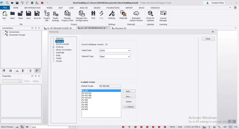
Ans 2:- 1. Created a new file in TSD and then in Home tab selected the materials options. Following dialog box appeared and in material option selected the material as steel and set the grade of steel as Fe410A.
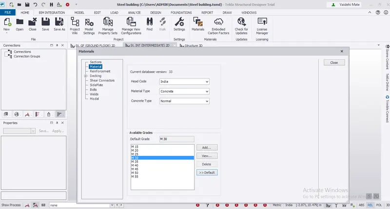
2. Now selected concrete in the material option and selected grade of concrete as M30 and set as default. Refer image below.
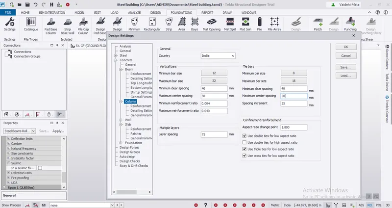
3. Column covers are changed in settings as follows:
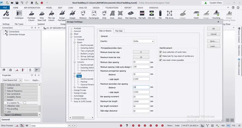
4. Slab cover are as follows:
5. Pile cap cover:
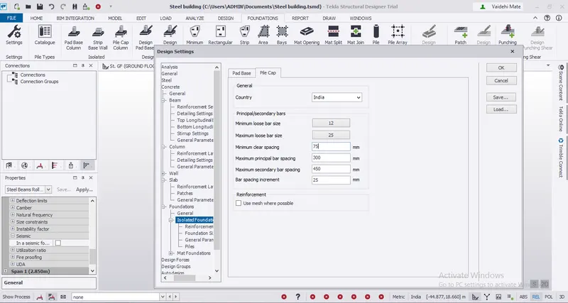
6. Foundation cover:
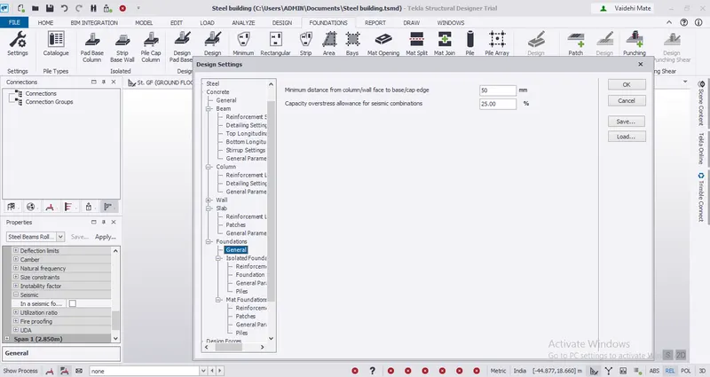
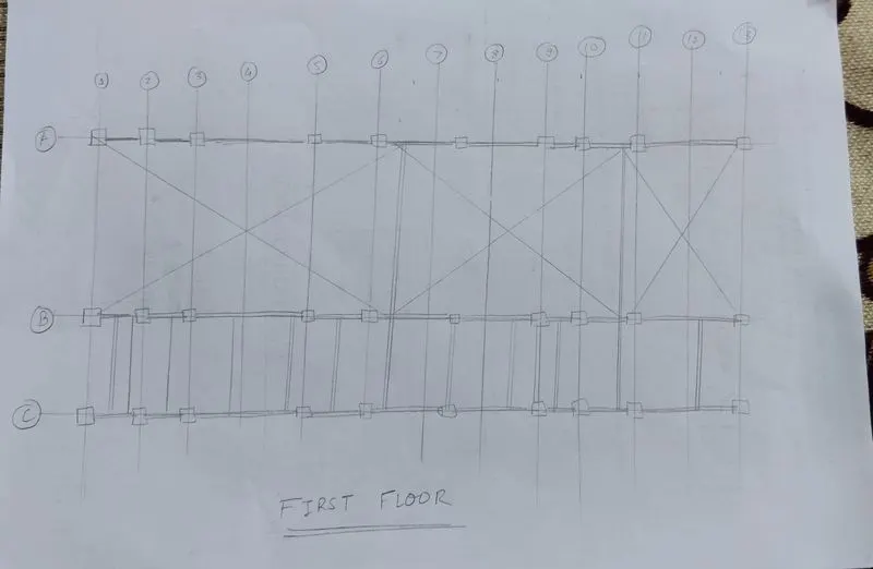
Ans 3. Now according to the attachment we have to insert beams and columns to support the structure. We usually provide column at the end of wall or its intersection. We need to provide beam to support the columns and the following walls.
This is a hand sketch of the beam and column placement.
Ans 4. Step 1- Modeled the grid according to the attachment. Refer to the images below.
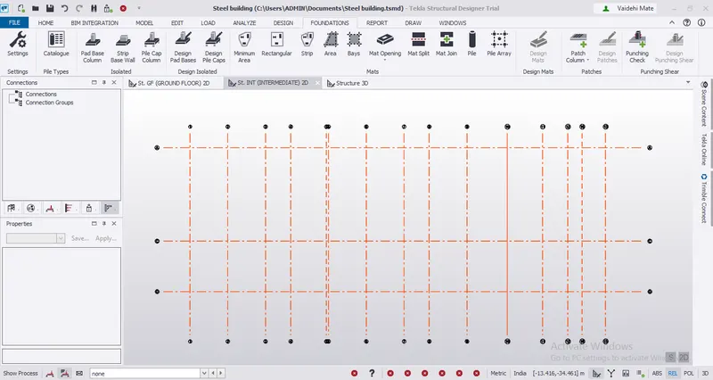
Step 2- Base level is 500 mm below Ground level.

Result- Successfully completed learning the basic visuals of TSD. Learned its primary setting and how to start the model. Modeled the grids for our structure.