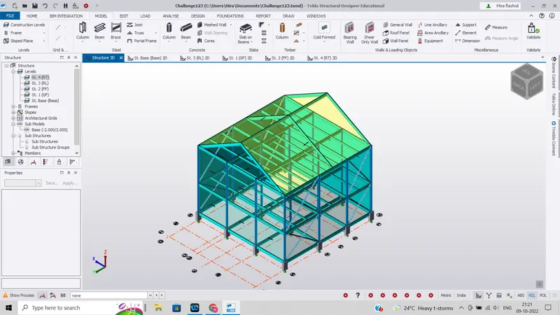
To model beams and bracings for industrial steel structures using TSD
1. Create beam properties for First floor and model the beams
AIM : To create beam properties and model primary and secondary beams on the Ground floor, First floor, Roof level
INTRODUCTION : Tekla structure, basic building objects are provided and detailed further. Columns, Beams is modelled and properties are assigned such as materials, alignments, supports, design code etc. Certain configurations are assigned before modelling the objects such as design code, analysis type, scenes, materials etc
PROCEDURE :
- Open Tekla software
- Click on Manage property sets
- Click on New
- Select steel beams
- Create Three types of beams and assign steel beam properties
- Three types of beams are taken :Beam 1 - ISMB250, Beam 2 - ISMB350, Beam 3 - ISMB500
- Untick autodesign in each of the beams
- Major alignment is taken as bottom in the beams
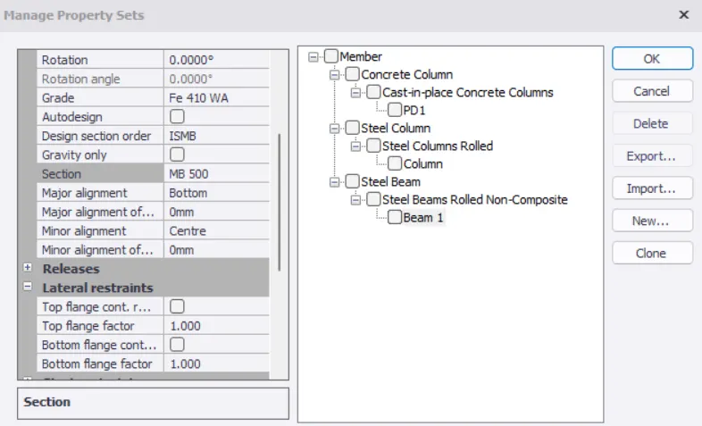
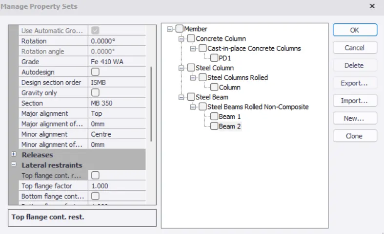
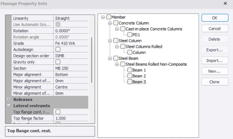
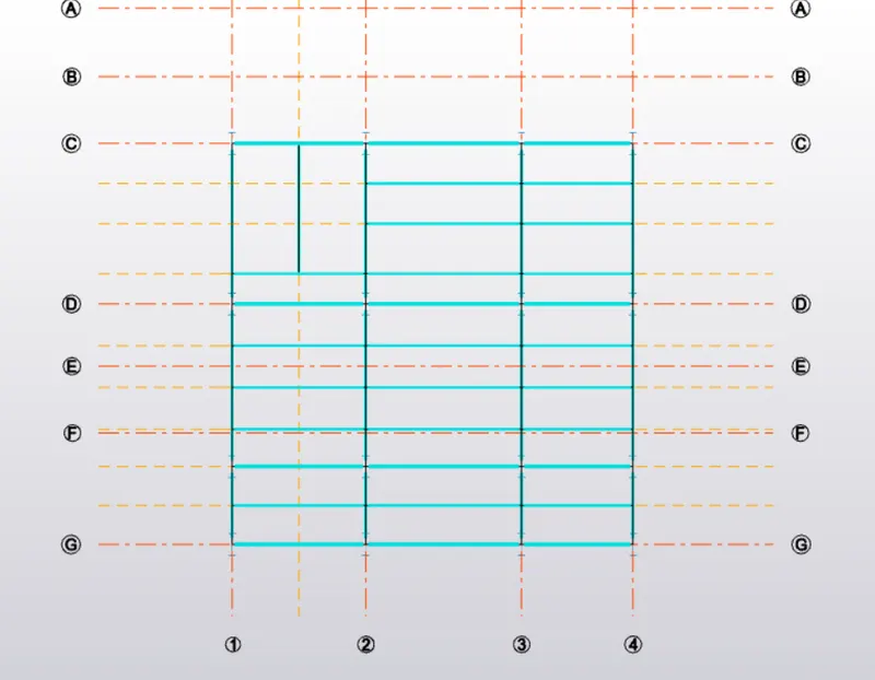
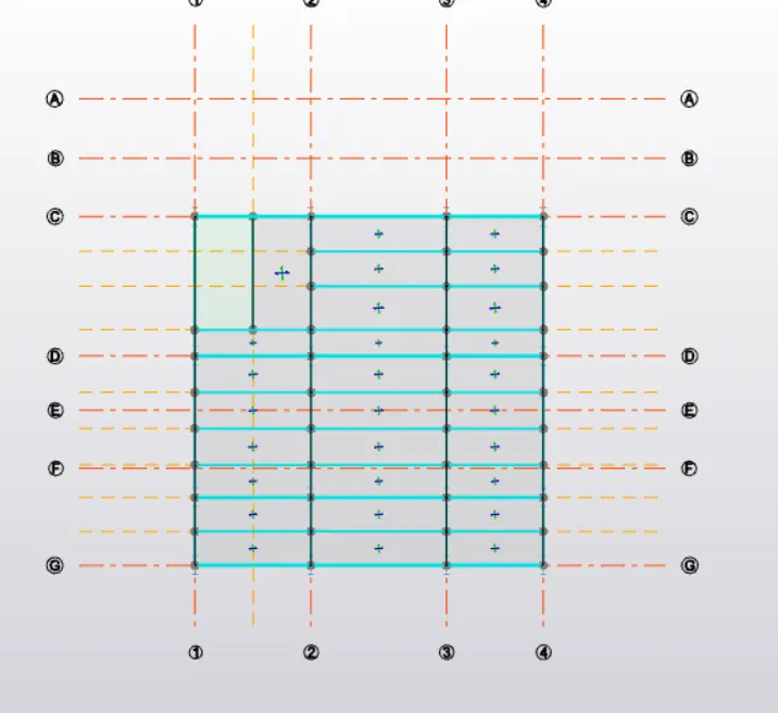
- Now place beams at the first floor
- MB 500 beams are placed Horizontally on plan
- MB 350 Beams are placed vertically on plan
- MB 250 beams are placed as secondary beams
RESULTS :
2. Create rafter beam on second floor as roof and moment frame action in one direction and add bracings at locations as per the design intent
AIM : 1. To create rafter beam on second floor as roof and moment frame action in one direction
2. Add bracings at suitable locations
INTRODUCTION :
Bracing system : Function of bracing is to provide stability and resist lateral loads, either from diagonal steel members or from a concrete 'core'. For bracing frames, beams and columns are designed only to support vertical load, since the bracing system should carry all lateral loads.
Rafters : A rafter is a structural component that is used as part of a roof construction. Typically, it runs from the ridge or hip of the roof to the wall plate of the external wall.
The Ridge Beam is the horizontal timber beam at the apex of the roof. It has no structural function but is the member against which the high ends of the rafters lean. It ensures that the rafters meet in a straight line and stay upright.
PROCEDURE :
- Go to model tab
- Go to manage property set
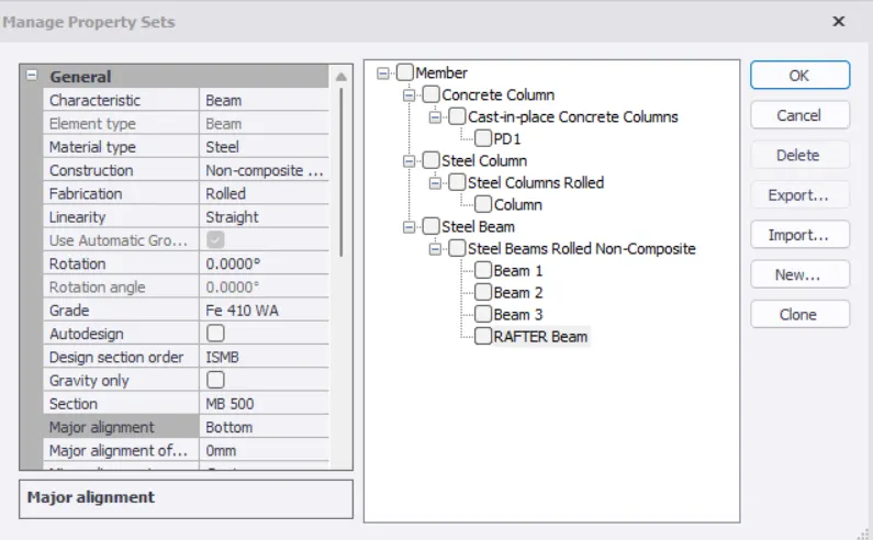
- Select new steel beam : Rafter
- Assign properties to the beam : Section is ISMB500, untick autodesign , Major aligment is bottom and Under releases both ends are fixed
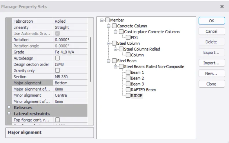
- Create another steel beam : Ridge beam
- Assign properties to the beam : Section is ISMB350, untick autodesign and Major aligment is bottom
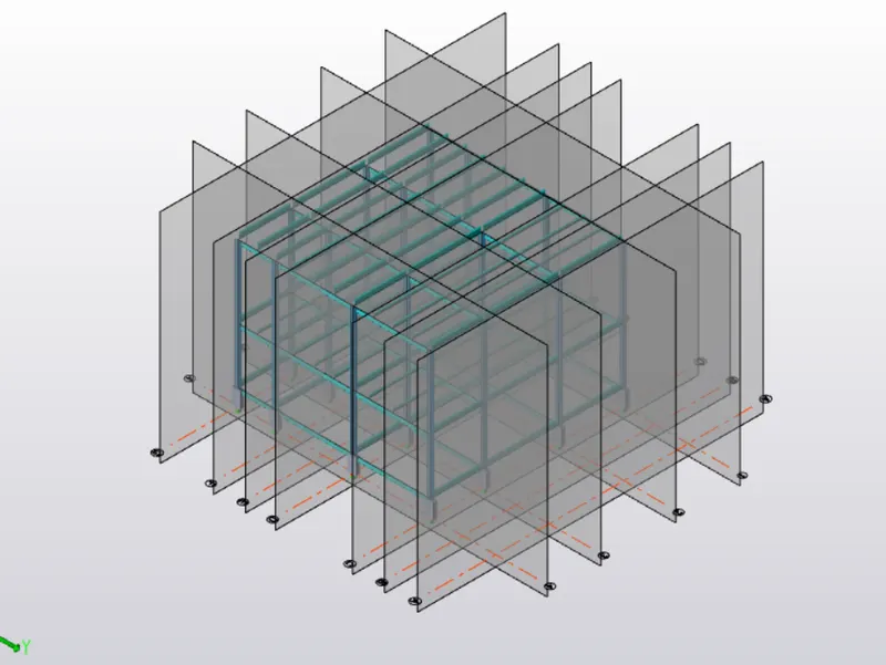
- Now Click on Frames
- Select all the grids and assign frames
- Now open FRAME 4
- Draw Construction line at midpoint between grids E and F
- Draw another Construction line above first floor level as shown below
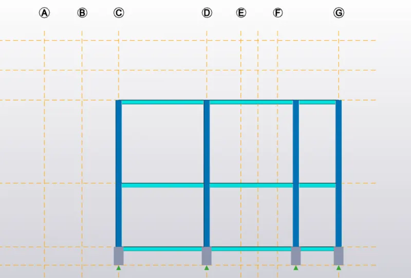
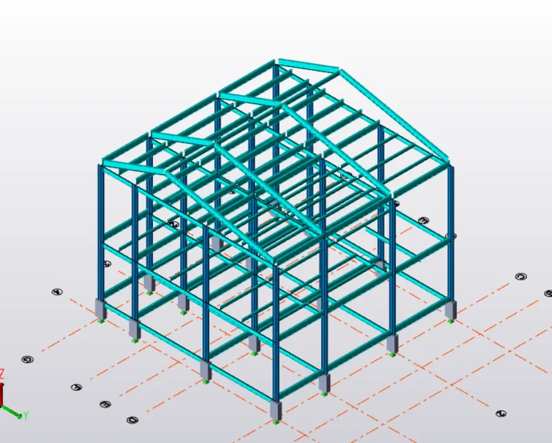
- From the intersecting point draw rafter beam connecting to both the end points
- Draw similar rafter beams at remaining grids
- Now place ridge beam on top of the rafter beams
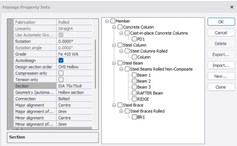
- Go to manage property sets
- Add new member : Steel brace
- Assign section as : Equal angle 75x75x8 size and Connection as bolted, Untick : Autodesign
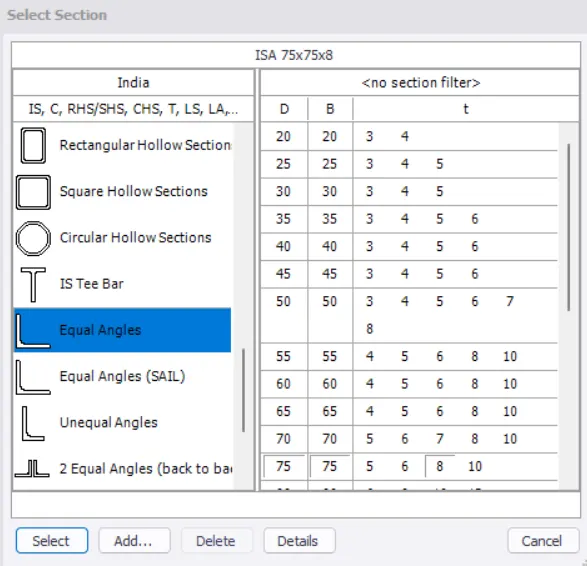
- Select brace - X from model and draw bracings in Frame C and G as shown below
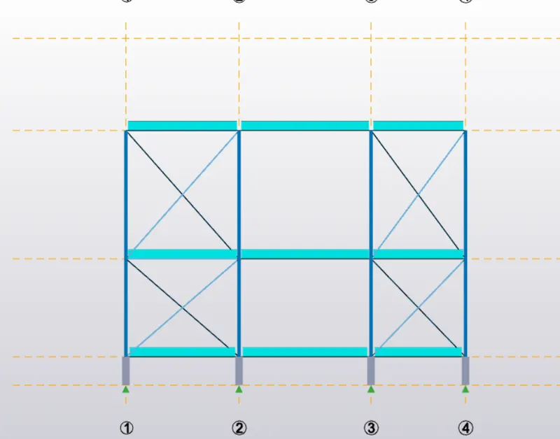
- Go to model and click on wall panel
- Draw wall panels at frame C, G as shown below
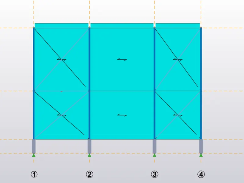
- Similarly draw wall panels at grid 1 and 4
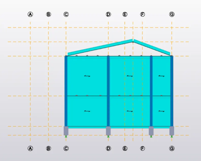
- Now click on Roof panel in the model tab and draw roof panels at rafter beams
- Go to manage property sets
- Click on new and create slab item
- Asssign properties to the slab : Slab type : Slab on beams, decomposition : twoway, depth taken as 200mm, grade taken as M25
- Untick autodesign
- Reinforcement details :
- For top and bottom bars (both inside and outside)
- Bar size 10mm
- Bar spacing 150mm
- For top and bottom bars (both inside and outside)
- After assigning properties, Go to model : click on slab on beams
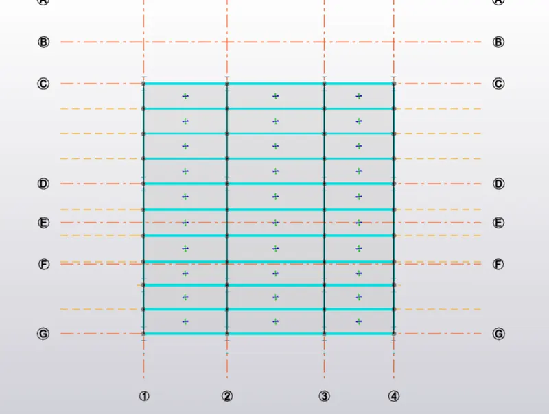
- Assign slabs in the ground floor, First floor and Top floor (angle : 90)
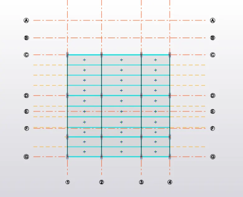
RESULT :