To Design RC column and beam for RC residential structure using TSD
Virtues to be noted:
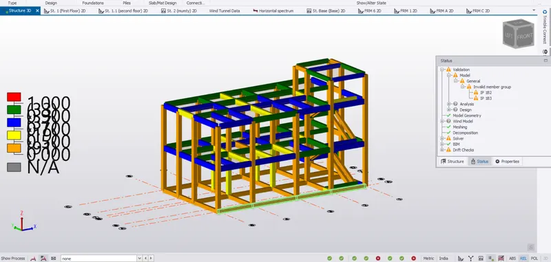
1. Above model shows "Strong Column & Weak Beam" Mechanism as All the beams are reaching first to the ductility limit and then followed by yieding of Column.
Legends shows:
0-0.5 Amost all Exterior Columns are showing this phenomenon.
0.5-0.7 all interior coulms are coming under this.
0.7-0.9 Exterior Beams/ Spendram Beams supported by Infills walls are coming under.
->0.9 comes under this.
We can consider the structure to be safe in Strength Criteria because we have considered the Brick walls as a load over the model but does not consider its bearing Support which if we dis-involve, resulting in Uneconomic Design.
OverConservative design whose possibility to reaching its ultimate state, doesn't exist in reality.
=====================================================================================
Below pic shows the Static Design of Members.
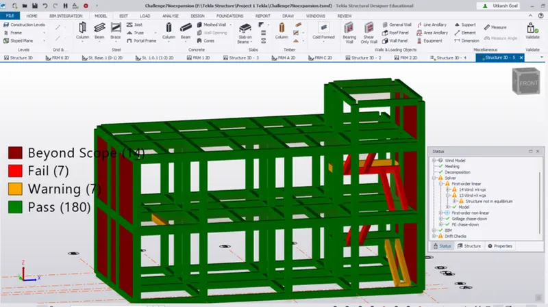
Shear Wall are mandatory here to prevent the Torsional Rotation in this Model.
( 30% of Total lateral force acting on this Model is resisted by Moment Frames resulting in Dual Frame System).
Observation: Due to more Openings to be provided along X axis, it is not possible to reconfigure the CR from the existing position to the middle of the plan.
Conclusion:
This model would be subjected to some sort of Torsion along both the axis, but We would have been trying to keep the Drift within the Limit.
============================================================================
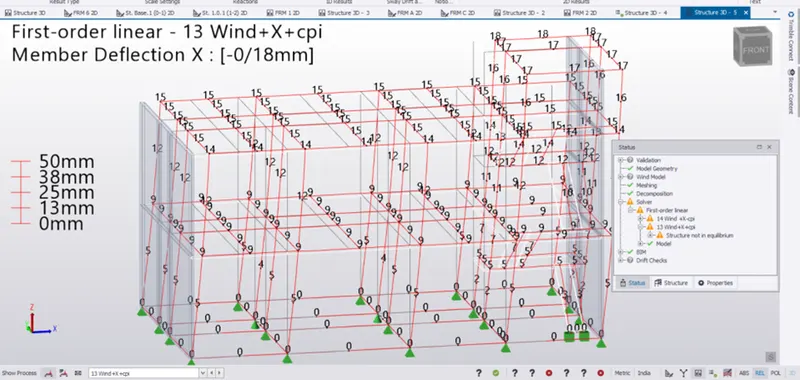
Deflection Dia. Due to Wind (X +Cpi) along the X axis
Observation:
1.Every level of this model get displaced equally along each floor.
| Floor / Level | Displacement/ Drift(along X axis) | |
| First Floor(4.8m) | 9 mm deflection(X axis) | |
| Second Floor(9.6m) | 15 & 14 mm, nearly same(NO Ambiguity) | |
| Mumty (12.6 m) | 18 & 17 mm | |
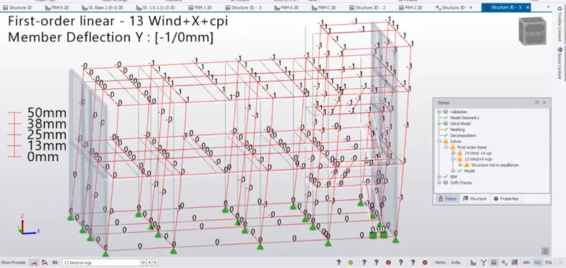
2. Due to Wind Force ( X + Cpi), Deflection diagram depicts the deviation from the 0 to -1 from the left side to Right Side respectively.
Conclusion:
Due to CR ( Center of Rigidity) accumulated at the mumty end, this model deflects along -Y axis on application of this model of Wind Force(X + Cpi). As this deflection(-1mm) is within the limit of Torsional Irregularity so NO WORRY.
===============================================================================
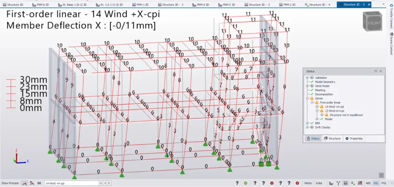
Deflection Dia. due to (Wind X - Cpi) along X axis, is shown above.
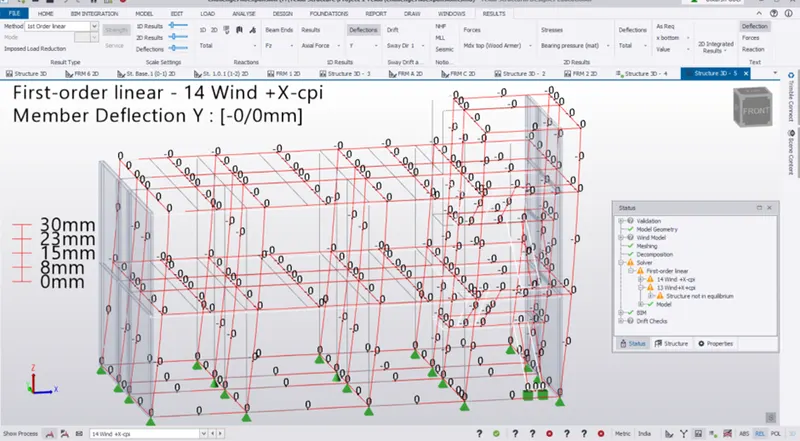
Deflection Diagram due to Wind (X - Cpi), along y Axis is shown above.
==============================================================================
Deflection Diagram due to Wind (Y + Cpi), is shown under:
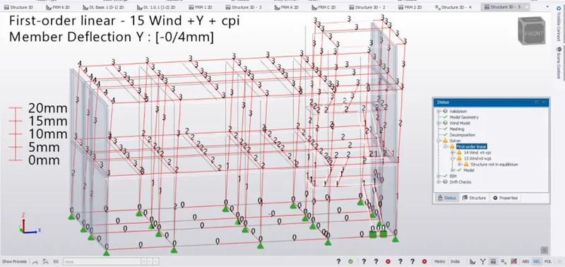
Observation:
1. On application of Wind (Y + Cpi) along Y axis, the right side of this model (3mm) deflects less than the left side (4mm) at the Second Floor of this model in the direction of applied Force.
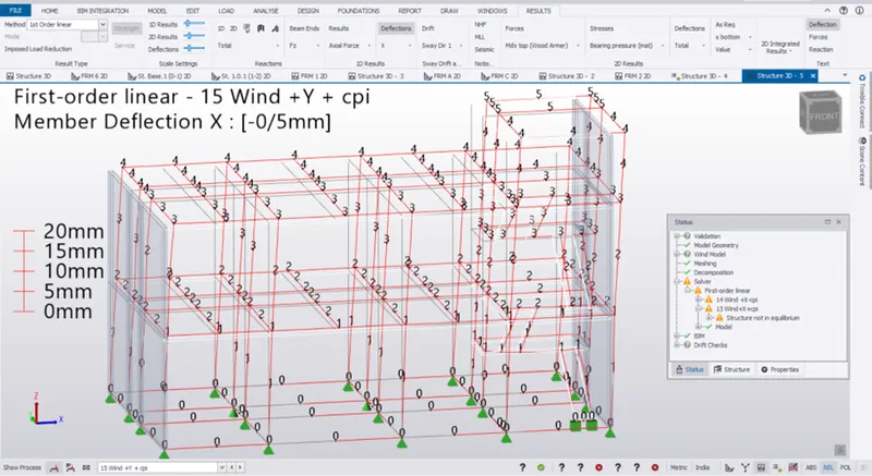
2. On application of Wind Load along Y axis, this get deflected completely along X axis as shown above.
Conclusion:
Due to CR concentated at the Front Facet of this model, this model deflected more pronouncily along its position, resulting total deflection along X-Y axis.(45 degree from the Force Axis)
==============================================================================
Wind (Y - Cpi)
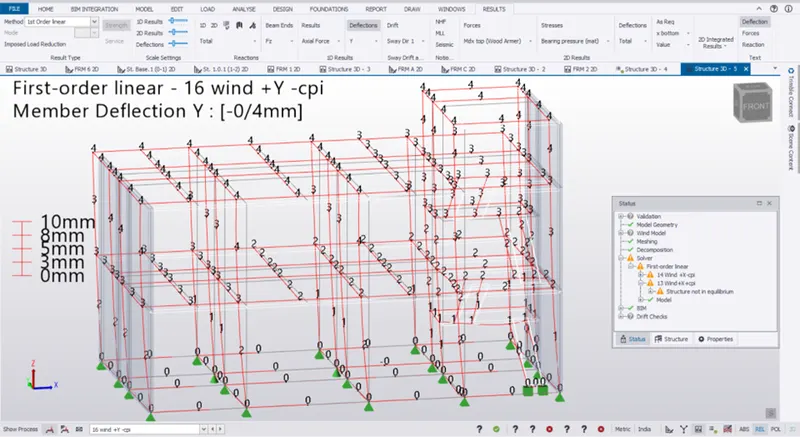
Observation:
On application of Wind Load (Y - Cpi), the left end(4mm) deflects more than the right side(3mm) at the second floor along the Y axis.
=============================================================================
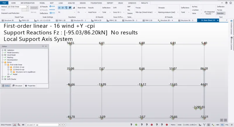
Reaction Force (Fz) due to wind load (Y - Cpi)
Observation:
1. Fz (Axial Force) under the column due to Wind (Y – Cpi) shows that Front facet of this model get subjected to tensile force while the leeward face is carrying the compressive Force.
2. Most of the Lateral Force acting along Y axis, is taken by the Shear Wall aligning along the Y axis with pairs shown in below table.
| Portion | Force Tensile(-) | Force Compressive (-) | Remarks |
| Left Side | -41.78 & -46.66 KN | 35.98 & 56.55 KN | These pairs are acting under the legs of Shear Wall. |
| Right Side | 95.03 & 53.31 KN | 44.01 & 86.2 KN | Compressive forces under the Shear Wall while Tensile Forces are acting along Stair leg(95.03 KN) as well as Under Shear leg (53.31 KN). |
Stair’s Stringer Beam on the right side of this model is working as a Shear wall with a tensile force of 95 KN as shown above.
===================================================================================
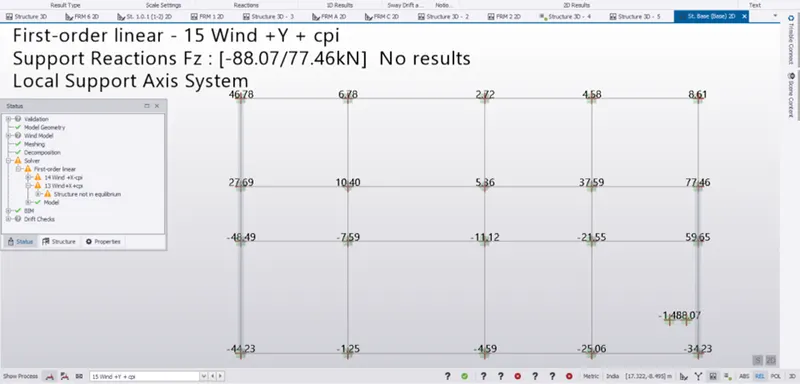
Wind ( Y + Cpi), same pattern as described in (Wind (Y-Cpi).
=============================================================================
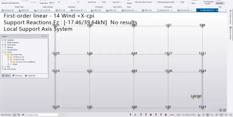
Wind (X - Cpi)
Observation:
1. Windward side along left side of above shot is having tensile forces under the columns while leeward side (Right Side) have compressive forces.
2. While summing the Axial force along a specific grid in the direction of Applied Force, the Summation of Forces will not nullify each other resulting discontinuity/ Stress concentration along the X direction.
3. But this is happening only at the portion far away from the CR,
Near the CR b/w Grid A & B,Summation of Forces can nullify each other.
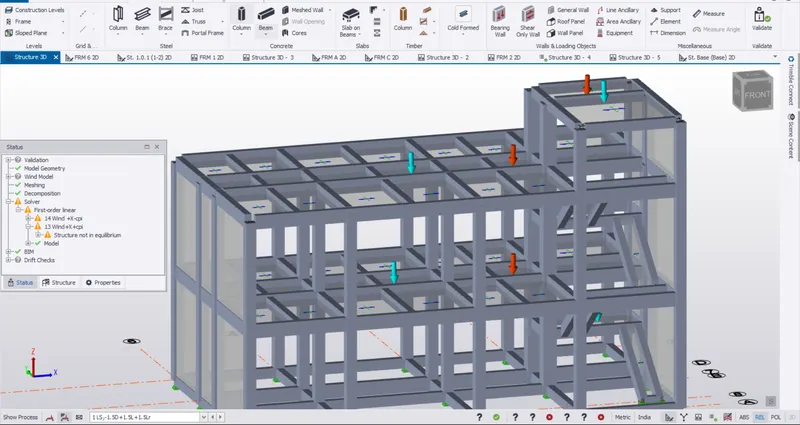
Red Label = Center of Rigidity
Blue Label= Center of Mass
================================================================================
Thanks & Regards to the mentor
Please Let me know about yu viewpoint & help to improve for the betterment of the society.