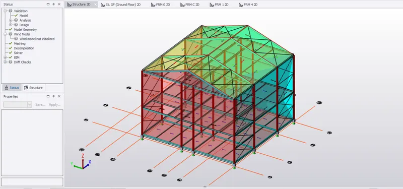
To calculate wind load for industrial steel structures and to apply it by using TSD
Aim: To calculate wind load for industrial steel structures and to apply it by using TSD
Introduction:
- Lateral Load Calculation and Application
- Validation of model after the loading Application
- Here first we will calculate the wind load manually
- And create the model to apply the load
- In the TEKLA Structural Designer we have a Option of calculating the wind load inside the software using the REC WiIZARD
- But here generaly our live projects we calculate the wind loand manualy and then applied on the Software
To creat the Wind and roof panel
- Open TEKLA Structureal Designed to software form my disktop
- Go to file menu to open the previous Challenge-4 Poject
- Now we wil Creat the Wind shield and Roof Sheild by using Wall and roof panel
- Go to Model , Under the model tab ther is option called Wall panel
- Selct Wall panel, then Pick the Point 1, Point 1, Point 2, Point 3, Point 4 Escape
- Similarly all the wind sheild are created
Aim: To Generate manual wind loading in the design report based IS code as per the following input
- Basic wind speed = 39m/s
- Terrain category 2
Procedure:
- Now To Calculate the wind load As per IS: 875 P3-2005
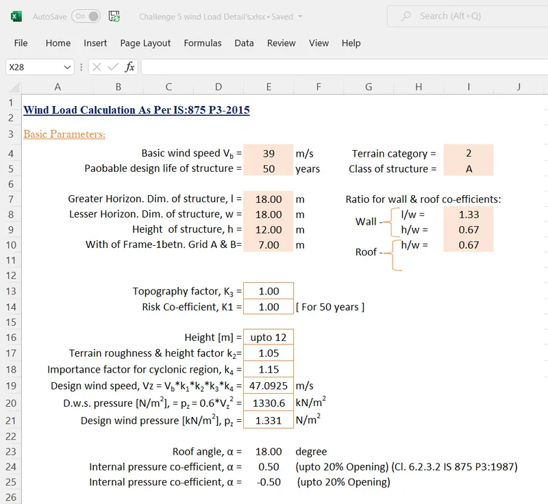
- Open the Excel Document File For Calculating the Wind load Calculation
- Initialy we wil Give the Basic Parmeters value of :
- Basic Wind speed Vb
- Probable design life of structure
- Terrain category
- Ratio for wall & roof co-efficient value
- Topography factor and etc...
- The Follwoing Calculation Are calculated by using IS: 875 P3-2005 Excel Document Fil
I. Wind Load Calculation:
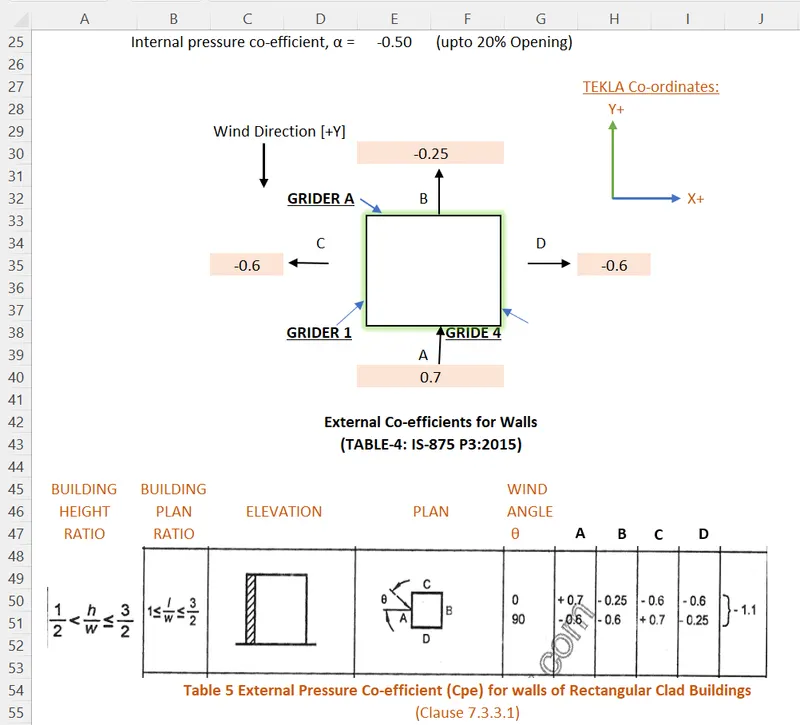
II. Tekla Co-ordinates and External Wall Roof Co-eficient :
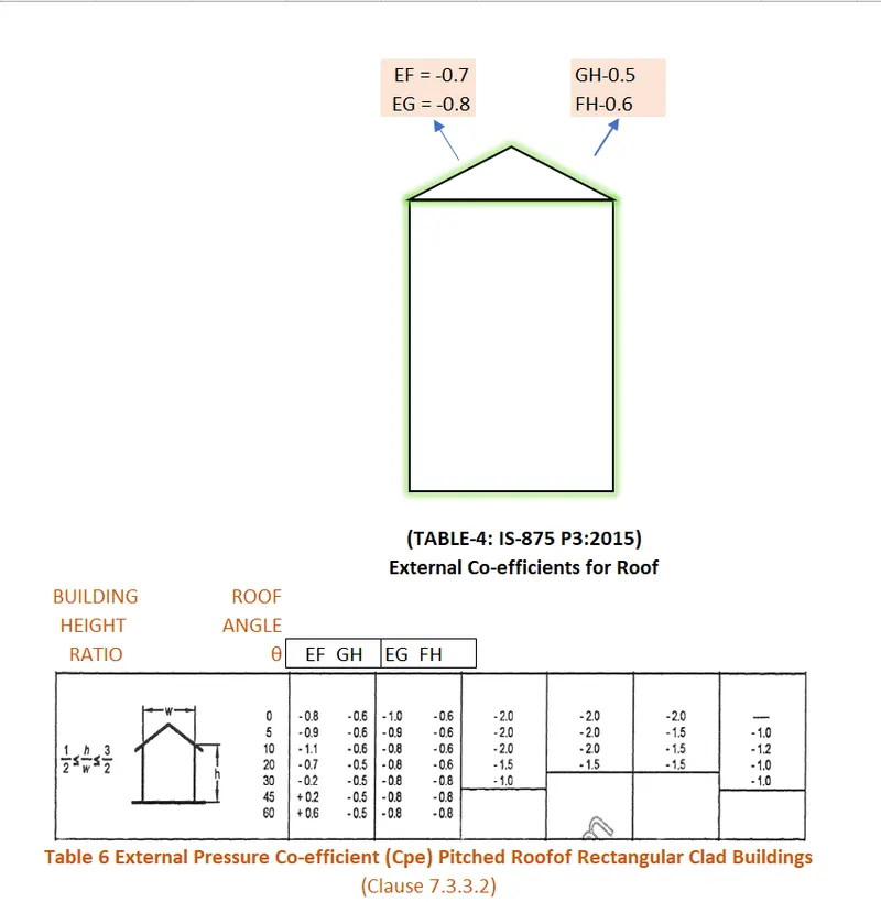
III. Roof Co-eficient :
IV. Wall Loading Calculation : Y direction
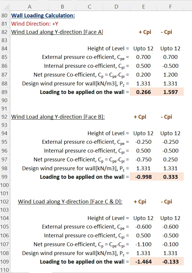
Similarly All wind load area calculated in the X-direction as the same procedure follwoed above
V. Roof Loading Calculation :
Wind load along Y- dorection (Roof EF and GH)
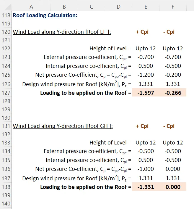
Vi. Roof Loading Calculation :
Wind load along X- dorection (Roof EG and FH)
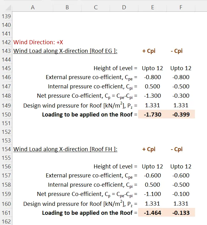
Result: The Wind load Manual calculation are calculated used Above the procedure by uisng Excel Docement File
Aim: To Based on the above calculation apply the loadings on the model
Procedure:
Step-1
- Now After Calculated of Wind load calculation To be apply the loading on the Model
- Take Previous Challenge File in TEKLA Software
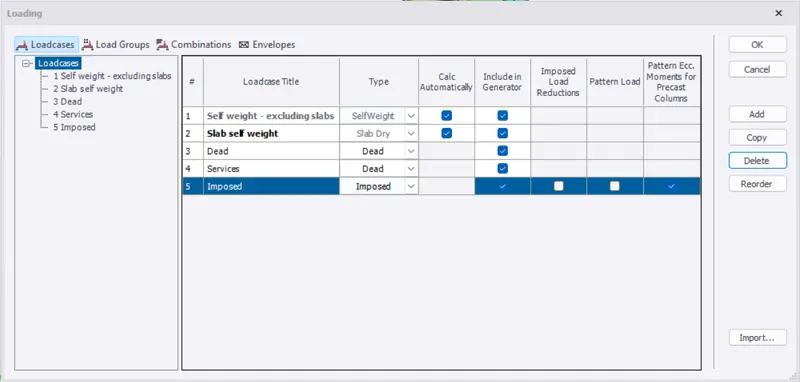
- Now we have to creat the Loadcase
- Select Loadcase Option are located in under the Load Tab
- Add add the Loadcases
- Type Wind +Y +Cpi
- Types of Load case as Wind
- Again Type Wind +Y -Cpi
- Types of Load case as Wind
- Again Type Wind +X +Cpi
- Types of Load case as Wind
- Again Type Wind +X -Cpi
- Types of Load case as Wind
- Similarly all the Load case are created as given below :
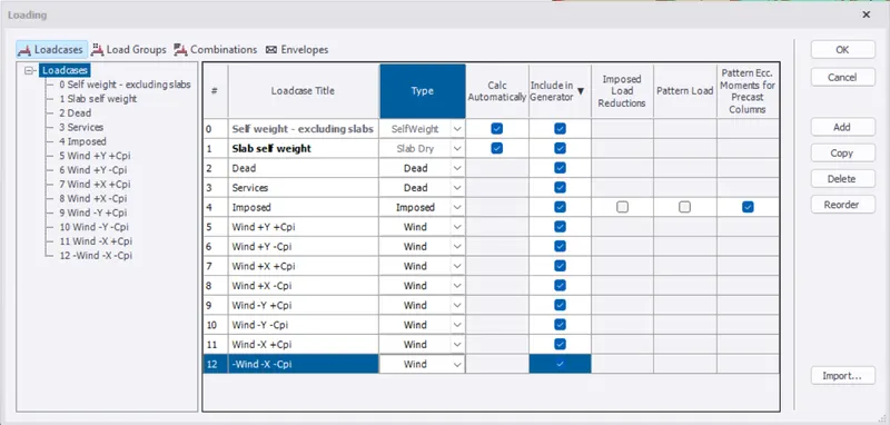
- Press Ok
- Now we have to start applyin the Load case
Step-2
- First we will to select the wind loasd case from bottom
- Then We will Input the value to apply the loadcase On Different Face
- The +X direction Grid G is: Face-A
- The Grid C is: Face-B
- The +Y Grid 1 is: Face-C
- The Grid C is: Face-D
- Next to go to Excel File
- And then chek the wind load value to apply on the model
To Wall Load:
i. Load case: +Y +Cpi
Face: A
- The Height Structure is Upto 12m
- load To be Apply on wall: 0.270 kN/m2
- Then Select the Which frame are we to be aplly
- Select the Frame G as Face A
- And seled Load case +Y +Cpi
- Go to Load Tab Select Area Loading
- The direction should be +y so its is acting towards the Building
- To chang Loding properties
- Load Type : Area Loading
- Direction : Global Y
- Measuring : Along Element
- Load : 0.270 kN/m2
- Then Aplly for each panel
Face: B
- Then chek the wind load value to apply on the model
- The Height Structure is Upto 12m
- load To be Apply on wall: -1.000 kN/m2
- Then Select the Which frame are we to be aplly
- Select the Frame G as Face B
- And seled Load case +Y +Cpi
- Go to Load Tab Select Area Loading
- The Load value is -Y so its is acting Away from the Building
- To chang Loding properties
- Load Type : Area Loading
- Direction : Global Y
- Measuring : Along Element
- Load : -1.000 kN/m2
- Then Aplly for each panel
- 3D view :
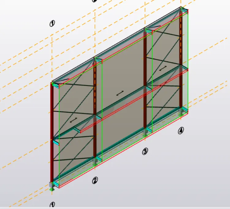
To Validate the Model:
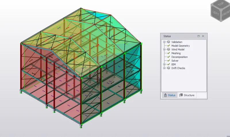
- No Error Hence ok
Face: C
- Then chek the wind load value to apply on the model
- The Height Structure is Upto 12m
- load To be Apply on wall: -1.464 kN/m2
- Then Select the Which frame are we to be aplly
- Select the Frame 1 as Face C
- And seled Load case +Y +Cpi
- Go to Load Tab Select Area Loading
- The Load value is -X so its is acting Away from the Building
- To chang Loding properties
- Load Type : Area Loading
- Direction : Global X
- Measuring : Along Element
- Load : -1.464 kN/m2
- Then Aplly for each panel
- 3D view :
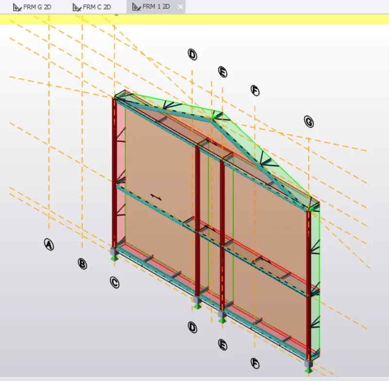
To Validate teh Model:
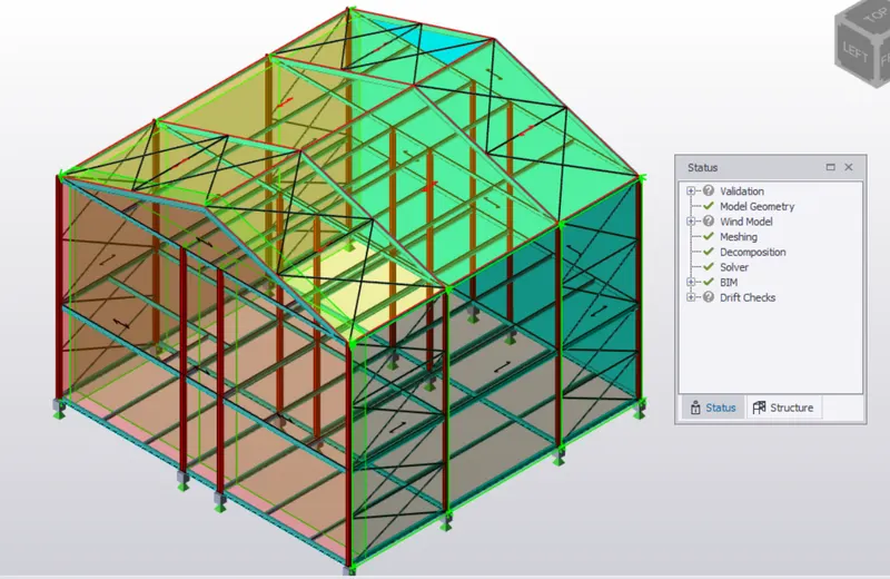
- No Error Hence ok
Face: D
- Then chek the wind load value to apply on the model
- The Height Structure is Upto 12m
- load To be Apply on wall: -1.464 kN/m2
- Then Select the Which frame are we to be aplly
- Select the Frame 4 as Face D
- And seled Load case +Y +Cpi
- Go to Load Tab Select Area Loading
- The Load value is -X so its is acting Away from the Building
- So Load value is putin in +X direction
- To chang Loding properties
- Load Type : Area Loading
- Direction : Global X
- Measuring : Along Element
- Load : 1.464 kN/m2
- Then Aplly for each panel
- 3D view :
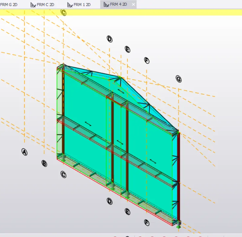
To Validate teh Model:
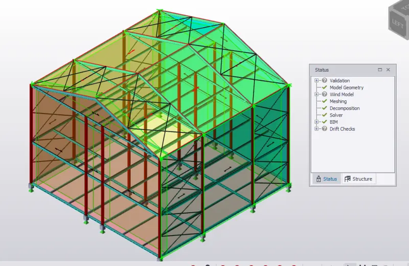
- No Error Hence ok
ii. Load case: +Y -Cpi
Face: A
- Then chek the wind load value to apply on the model
- The Height Structure is Upto 12m
- load To be Apply on wall: -0.340 kN/m2
- Then Select the Which frame are we to be aplly
- Select the Frame C as Face A
- And seled Load case +Y -Cpi
- Go to Load Tab Select Area Loading
- The direction should be +y so its is acting towards the Building
- To chang Loding properties
- Load Type : Area Loading
- Direction : Global Y
- Measuring : Along Element
- Load : -0.340 kN/m2
- Then Aplly for each panel
- 3D view :
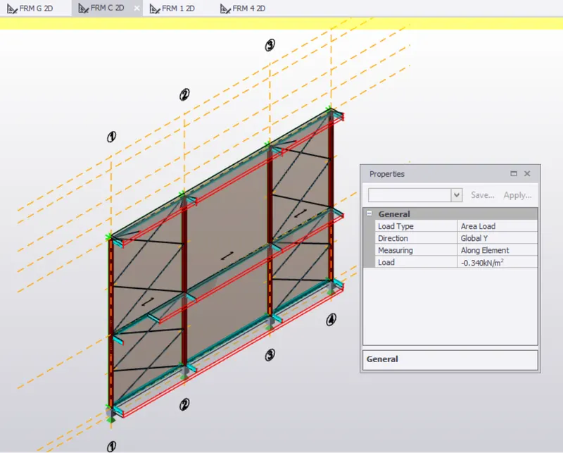
To Validate teh Model:
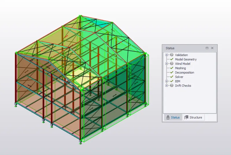
- No Error Hence ok
Face: B
- Then chek the wind load value to apply on the model
- The Height Structure is Upto 12m
- load To be Apply on wall: 1.600 kN/m2
- Then Select the Which frame are we to be aplly
- Select the Frame G as Face B
- And seled Load case +Y -Cpi
- Go to Load Tab Select Area Loading
- The direction should be +y so its is acting towards the Building
- To chang Loding properties
- Load Type : Area Loading
- Direction : Global Y
- Measuring : Along Element
- Load : 1.600 kN/m2
- Then Aplly for each panel
- 3D view :
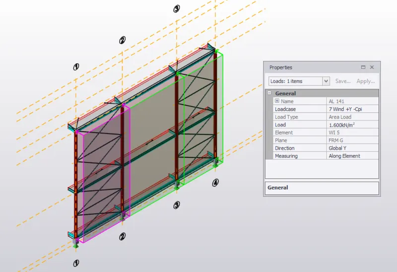
To Validate teh Model:
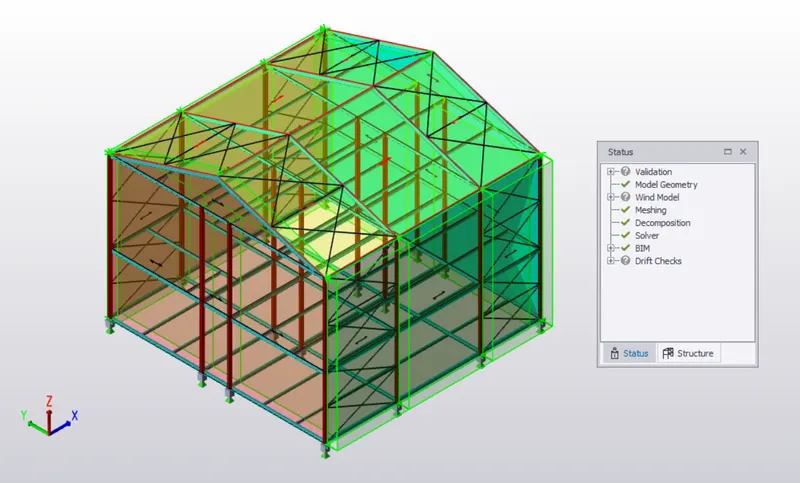
- No Error Hence ok
Face: C
- Then chek the wind load value to apply on the model
- The Height Structure is Upto 12m
- load To be Apply on wall: -0.140 kN/m2
- Then Select the Which frame are we to be aplly
- Select the Frame 1 as Face C
- And seled Load case +Y -Cpi
- Go to Load Tab Select Area Loading
- The Load value is -X so its is acting Away from the Building
- To chang Loding properties
- Load Type : Area Loading
- Direction : Global X
- Measuring : Along Element
- Load : -0.140 kN/m2
- Then Aplly for each panel
- 3D view :
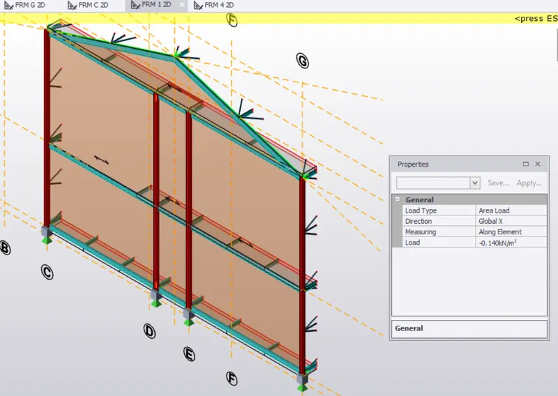
To Validate teh Model:
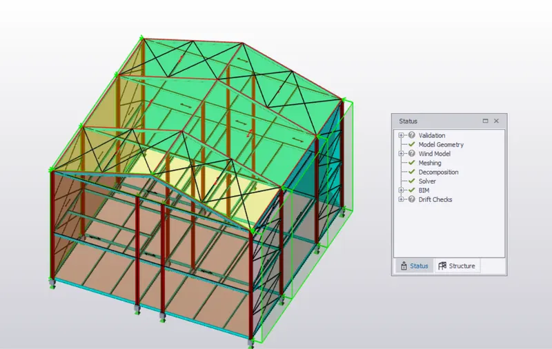
- No Error Hence ok
Face: D
- Then chek the wind load value to apply on the model
- The Height Structure is Upto 12m
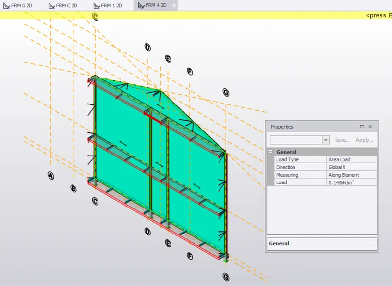
- load To be Apply on wall: 0.140 kN/m2
- Then Select the Which frame are we to be aplly
- Select the Frame 4 as Face D
- And seled Load case +Y -Cpi
- Go to Load Tab Select Area Loading
- The Load value is +X so its is acting Away from the Building
- So Load value is putin in +X direction
- To chang Loding properties
- Load Type : Area Loading
- Direction : Global X
- Measuring : Along Element
- Load : 0.140 kN/m2
- Then Aplly for each panel
- 3D view :
To Validate teh Model:
- No Error Hence ok
iii. Load case: -Y +Cpi
Face: A
- Then chek the wind load value to apply on the model
- The Height Structure is Upto 12m
- load To be Apply on wall: -1.000 kN/m2
- Then Select the Which frame are we to be aplly
- Select the Frame C as Face A
- And seled Load case -Y +Cpi
- Go to Load Tab Select Area Loading
- The direction should be -y so its is acting towards the Building
- To chang Loding properties
- Load Type : Area Loading
- Direction : Global Y
- Measuring : Along Element
- Load : -1.000 kN/m2
- Then Aplly for each panel
- 3D view:
To Validate teh Model:
- No Error Hence ok
Face: B
- Then chek the wind load value to apply on the model
- The Height Structure is Upto 12m
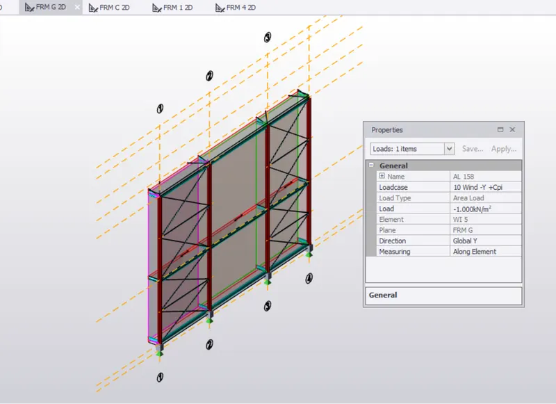
- load To be Apply on wall: -1.000 kN/m2
- Then Select the Which frame are we to be aplly
- Select the Frame G as Face B
- And seled Load case -Y +Cpi
- Go to Load Tab Select Area Loading
- The Load value is -Y so its is acting Away from the Building
- To chang Loding properties
- Load Type : Area Loading
- Direction : Global Y
- Measuring : Along Element
- Load : -1.000 kN/m2
- Then Aplly for each panel
- 3D view :
To Validate the Model:
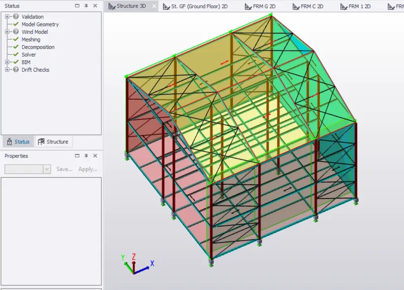
- No Error Hence ok
Face: C
- Then chek the wind load value to apply on the model
- The Height Structure is Upto 12m
- load To be Apply on wall: -1.464 kN/m2
- Then Select the Which frame are we to be aplly
- Select the Frame 1 as Face C
- And seled Load case -Y +Cpi
- Go to Load Tab Select Area Loading
- The Load value is -X so its is acting Away from the Building
- To chang Loding properties
- Load Type : Area Loading
- Direction : Global X
- Measuring : Along Element
- Load : -1.464 kN/m2
- Then Aplly for each panel
- 3D view :
To Validate the Model:
- No Error Hence ok
Face: D
- Then chek the wind load value to apply on the model
- The Height Structure is Upto 12m
- load To be Apply on wall: 1.464 kN/m2
- Then Select the Which frame are we to be aplly
- Select the Frame 4 as Face D
- And seled Load case -Y +Cpi
- Go to Load Tab Select Area Loading
- The Load value is +X so its is acting Away from the Building
- So Load value is putin in +X direction
- To chang Loding properties
- Load Type : Area Loading
- Direction : Global X
- Measuring : Along Element
- Load : 1.464 kN/m2
- Then Aplly for each panel
- 3D view :
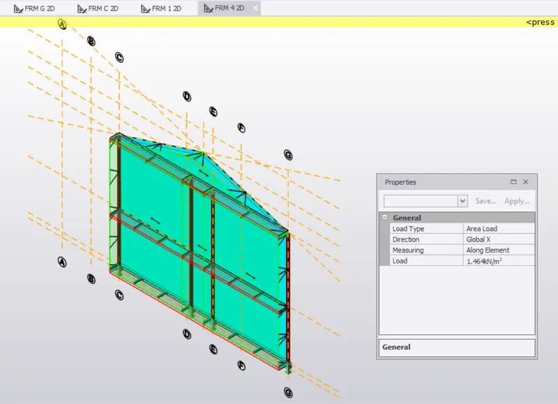
To Validate teh Model:
- No Error Hence ok
iv. Load case: -Y -Cpi
Face: A
- Then chek the wind load value to apply on the model
- The Height Structure is Upto 12m
- load To be Apply on wall: -1.600 kN/m2
- Then Select the Which frame are we to be aplly
- Select the Frame C as Face A
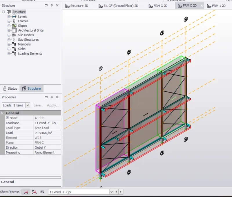
- And seled Load case -Y -Cpi
- Go to Load Tab Select Area Loading
- The direction should be -y so its is acting towards the Building
- To chang Loding properties
- Load Type : Area Loading
- Direction : Global Y
- Measuring : Along Element
- Load : -1.600 kN/m2
- Then Aplly for each panel
- 3D view:
To Validate the Model:
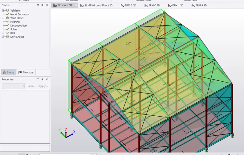
- No Error Hence ok
Face: B
- Then chek the wind load value to apply on the model
- The Height Structure is Upto 12m
- load To be Apply on wall: 0.333 kN/m2
- Then Select the Which frame are we to be aplly
- Select the Frame C as Face A
- And seled Load case -Y -Cpi
- Go to Load Tab Select Area Loading
- The direction should be -y so its is acting towards the Building
- To chang Loding properties
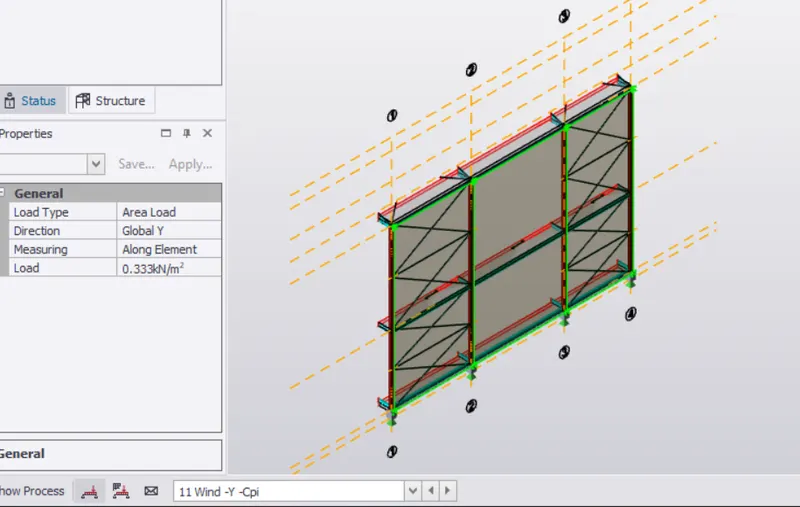
- Load Type : Area Loading
- Direction : Global Y
- Measuring : Along Element
- Load : 0.333 kN/m2
- Then Aplly for each panel
- 3D view:
To Validate the Model:
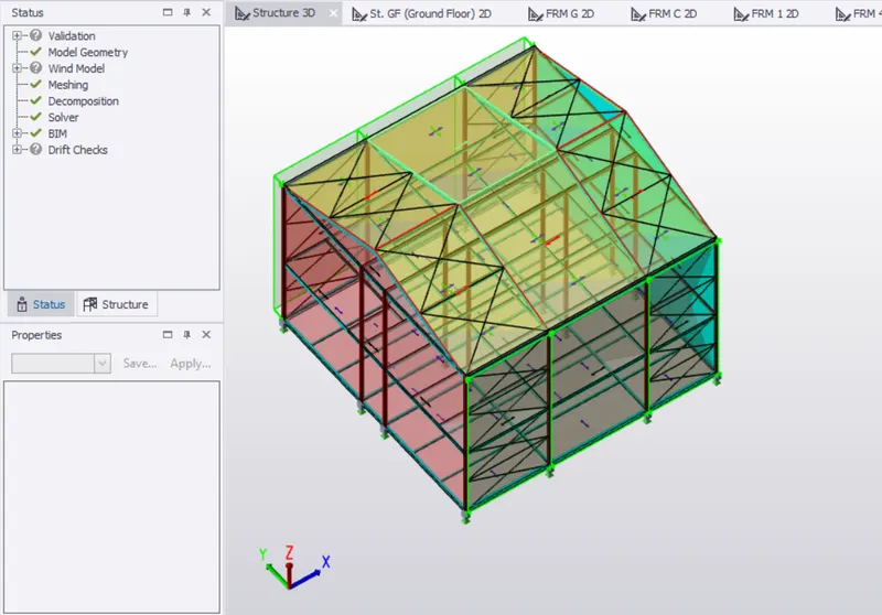
- No Error Hence ok
Face: C
- Then chek the wind load value to apply on the model
- The Height Structure is Upto 12m
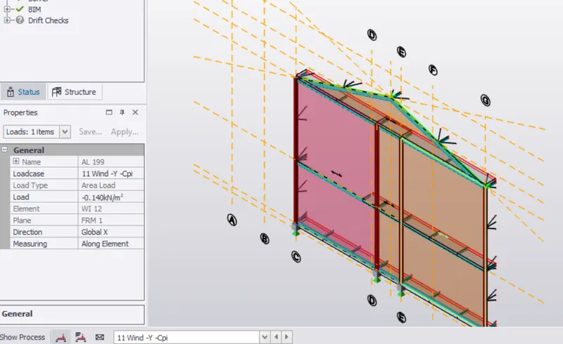
- load To be Apply on wall: -0.140 kN/m2
- Then Select the Which frame are we to be aplly
- Select the Frame 1 as Face C
- And seled Load case -Y -Cpi
- Go to Load Tab Select Area Loading
- The Load value is -X so its is acting Away from the Building
- To chang Loding properties
- Load Type : Area Loading
- Direction : Global X
- Measuring : Along Element
- Load : -0.140 kN/m2
- Then Aplly for each panel
- 3D view :
To Validate teh Model:
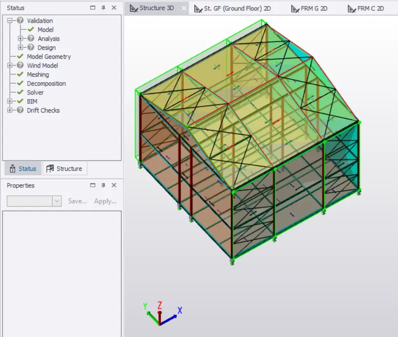
- No Error Hence ok
Face: D
- Then chek the wind load value to apply on the model
- The Height Structure is Upto 12m
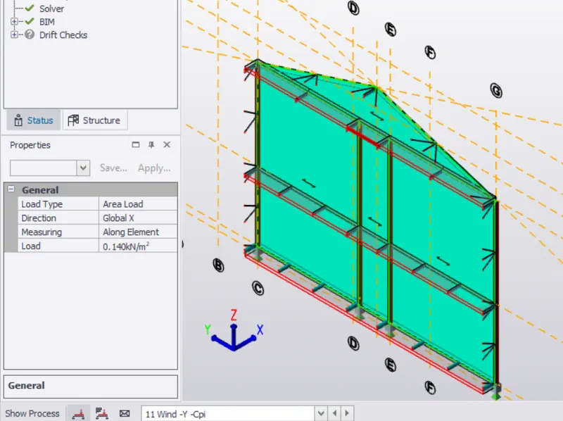
- load To be Apply on wall: 0.140 kN/m2
- Then Select the Which frame are we to be aplly
- Select the Frame 1 as Face C
- And seled Load case -Y -Cpi
- Go to Load Tab Select Area Loading
- The Load value is X so its is acting Away from the Building
- To chang Loding properties
- Load Type : Area Loading
- Direction : Global X
- Measuring : Along Element
- Load : 0.140 kN/m2
- Then Aplly for each panel
- 3D view :
To Validate the Model:
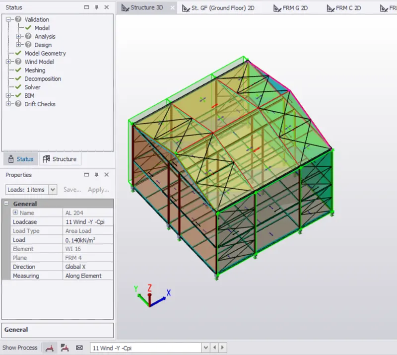
- No Error Hence ok
Hence The Loadcase, Wind +Y +Cpi , Wind +Y -Cpi , Wind -Y +Cpi , Wind -Y -Cpi Are finished
Similarly The Wind +X +Cpi, Wind +X Cpi, Wind -X +Cpi, Wind -X -Cpi, also Modeled..
To Roof Load:
- Similar Above the Wall loadcase to be aplly Roof load
- Wind loading along Y direction
Wind Direction +Y
i. Load case: +Y +Cpi
Roof EF:
- The Height Structure is Upto 12m
- load To be Apply on Roof: -1.597 kN/m2
- Then Select the Which frame are we to be aplly
- Select the Structure 3D view
- Go to Load Tab Select Area Loading
- To chang Loding properties
- Load Type : Area Loading
- Direction : Global Y
- Measuring : Along Element
- Load : -1.597 kN/m2
- Then Aplly for each panel
Roof GH:
- The Height Structure is Upto 12m
- load To be Apply on Roof: -1.331 kN/m2
- Then Select the Which frame are we to be aplly
- Select the Structure 3D view
- Go to Load Tab Select Area Loading
- To chang Loding properties
- Load Type : Area Loading
- Direction : Global Y
- Measuring : Along Element
- Load : -1.331 kN/m2
- Then Aplly for each panel
ii. Load case: +Y -Cpi
Roof EF:
- The Height Structure is Upto 12m
- load To be Apply on Roof: -0.266 kN/m2
- Then Select the Which frame are we to be aplly
- Select the Structure 3D view
- Go to Load Tab Select Area Loading
- To chang Loding properties
- Load Type : Area Loading
- Direction : Global Y
- Measuring : Along Element
- Load : -0.266 kN/m2
- Then Aplly for each panel
Roof GH:
- The Height Structure is Upto 12m
- load To be Apply on Roof: 0 kN/m2
- Then Select the Which frame are we to be aplly
- Select the Structure 3D view
- Go to Load Tab Select Area Loading
- To chang Loding properties
- Load Type : Area Loading
- Direction : Global Y
- Measuring : Along Element
- Load : 0
- Then Aplly for each panel
iii. Load case: -Y +Cpi
Here Direction of face will change.
Roof EF:
- The Height Structure is Upto 12m
- load To be Apply on Roof: -1.597 kN/m2
- Then Select the Which frame are we to be aplly
- Select the Structure 3D view
- Go to Load Tab Select Area Loading
- To chang Loding properties
- Load Type : Area Loading
- Direction : Global Y
- Measuring : Along Element
- Load : -1.597 kN/m2
- Then Aplly for each panel
Roof GH:
- The Height Structure is Upto 12m
- load To be Apply on Roof: -1.331 kN/m2
- Then Select the Which frame are we to be aplly
- Select the Structure 3D view
- Go to Load Tab Select Area Loading
- To chang Loding properties
- Load Type : Area Loading
- Direction : Global Y
- Measuring : Along Element
- Load : -1.331 kN/m2
- Then Aplly for each panel
iV. Load case: -Y -Cpi
Roof EF:
- The Height Structure is Upto 12m
- load To be Apply on Roof: -0.266 kN/m2
- Then Select the Which frame are we to be aplly
- Select the Structure 3D view
- Go to Load Tab Select Area Loading
- To chang Loding properties
- Load Type : Area Loading
- Direction : Global Y
- Measuring : Along Element
- Load : -0.266 kN/m2
- Then Aplly for each panel
Roof GH:
- The Height Structure is Upto 12m
- load To be Apply on Roof: 0 kN/m2
- Then Select the Which frame are we to be aplly
- Select the Structure 3D view
- Go to Load Tab Select Area Loading
- To chang Loding properties
- Load Type : Area Loading
- Direction : Global Y
- Measuring : Along Element
- Load : 0
- Then Aplly for each panel
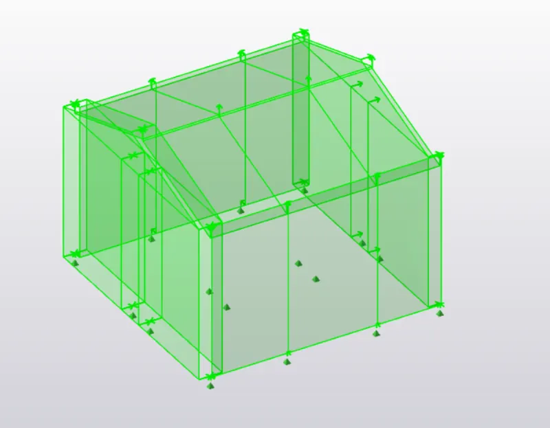
To Validate the Model:
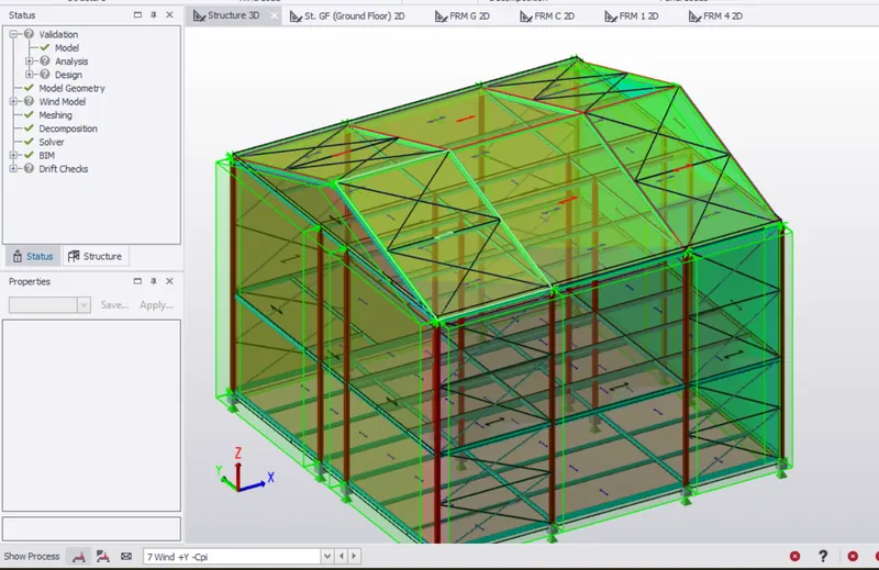
Wind Direction +X
- Similar Above the Wall loadcase to be aplly Roof load
- Wind loading along Y direction
i. Load case: +X +Cpi
Roof EG:
- The Height Structure is Upto 12m
- load To be Apply on Roof: -1.730 kN/m2
- Then Select the Which frame are we to be aplly
- Select the Structure 3D view
- Go to Load Tab Select Area Loading
- To chang Loding properties
- Load Type : Area Loading
- Direction : Global X
- Measuring : Along Element
- Load : -1.730 kN/m2
- Then Aplly for each panel
Roof FH:
- The Height Structure is Upto 12m
- load To be Apply on Roof: -1.464 kN/m2
- Then Select the Which frame are we to be aplly
- Select the Structure 3D view
- Go to Load Tab Select Area Loading
- To chang Loding properties
- Load Type : Area Loading
- Direction : Global X
- Measuring : Along Element
- Load : -1.464 kN/m2
- Then Aplly for each panel
ii. Load case: +X -Cpi
Roof EG:
- The Height Structure is Upto 12m
- load To be Apply on Roof: -0.399 kN/m2
- Then Select the Which frame are we to be aplly
- Select the Structure 3D view
- Go to Load Tab Select Area Loading
- To chang Loding properties
- Load Type : Area Loading
- Direction : Global X
- Measuring : Along Element
- Load : -0.399 kN/m2
- Then Aplly for each panel
Roof FH:
- The Height Structure is Upto 12m
- load To be Apply on Roof: -0.133kN/m2
- Then Select the Which frame are we to be aplly
- Select the Structure 3D view
- Go to Load Tab Select Area Loading
- To chang Loding properties
- Load Type : Area Loading
- Direction : Global X
- Measuring : Along Element
- Load : -0.133 kN/m2
- Then Aplly for each panel
iii. Load case: -X +Cpi
Here Direction of Face will change, load will be changing
Roof EG:
- The Height Structure is Upto 12m
- load To be Apply on Roof: -1.464 kN/m2
- Then Select the Which frame are we to be aplly
- Select the Structure 3D view
- Go to Load Tab Select Area Loading
- To chang Loding properties
- Load Type : Area Loading
- Direction : Global X
- Measuring : Along Element
- Load : -1.464 kN/m2
- Then Aplly for each panel
Roof FH:
- The Height Structure is Upto 12m
- load To be Apply on Roof: -1.730 kN/m2
- Then Select the Which frame are we to be aplly
- Select the Structure 3D view
- Go to Load Tab Select Area Loading
- To chang Loding properties
- Load Type : Area Loading
- Direction : Global X
- Measuring : Along Element
- Load : -1.730 kN/m2
- Then Aplly for each panel
iv. Load case: -X -Cpi
Roof EG:
- The Height Structure is Upto 12m
- load To be Apply on Roof: -0.133 kN/m2
- Then Select the Which frame are we to be aplly
- Select the Structure 3D view
- Go to Load Tab Select Area Loading
- To chang Loding properties
- Load Type : Area Loading
- Direction : Global X
- Measuring : Along Element
- Load : -0.133 kN/m2
- Then Aplly for each panel
Roof FH:
- The Height Structure is Upto 12m
- load To be Apply on Roof: -0.399 kN/m2
- Then Select the Which frame are we to be aplly
- Select the Structure 3D view
- Go to Load Tab Select Area Loading
- To chang Loding properties
- Load Type : Area Loading
- Direction : Global X
- Measuring : Along Element
- Load : -0.399 kN/m2
- Then Aplly for each panel
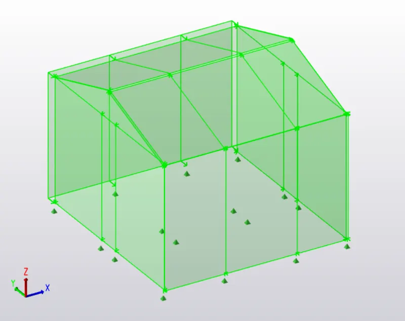
To Validate the Model:
Result: Hence The Mnaula wind load calculation and aplying Model are finished
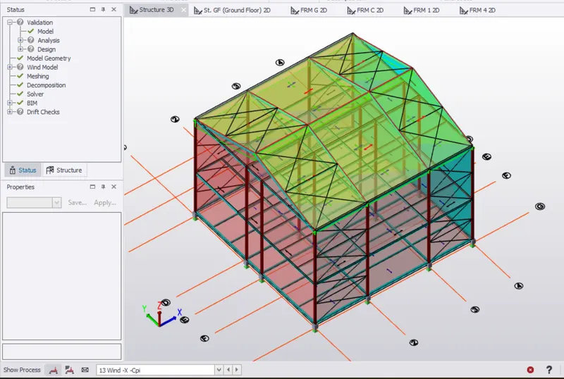
Q:3
Aim: To On a separate model generate wind loading using wind wizard
Procedure:
- Before the We save this model and go through the wilnd load calculation using Winwizard of the Tekla Software
- Then delete the our load combination of the manul loading
- Go to WinWizard
- Select the option Worst Case Data
- Option: CONSIDER tOPHPGRAPHY
- Consider Cylonic Effect
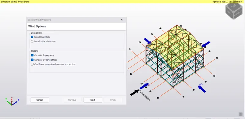
- Press Next
- Once we click next Design Wind pressure tab will be Appear on display
- Here Building Height 12m ( Override calculated)
- Building type: All general buildings
- Structure type - post cyclonic importance : Intusdrial structure
- Then Basic wind speed, Vb : 39
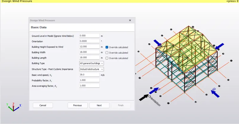
- Press Next
- Then select Terrain Category : 2) Open terrain scattered obstrudions
- Fetch a distance: 7
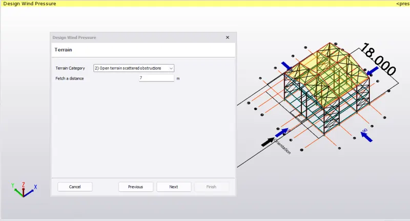
- Press Next
- Topography tab appear on display
- Here we haven't change anything
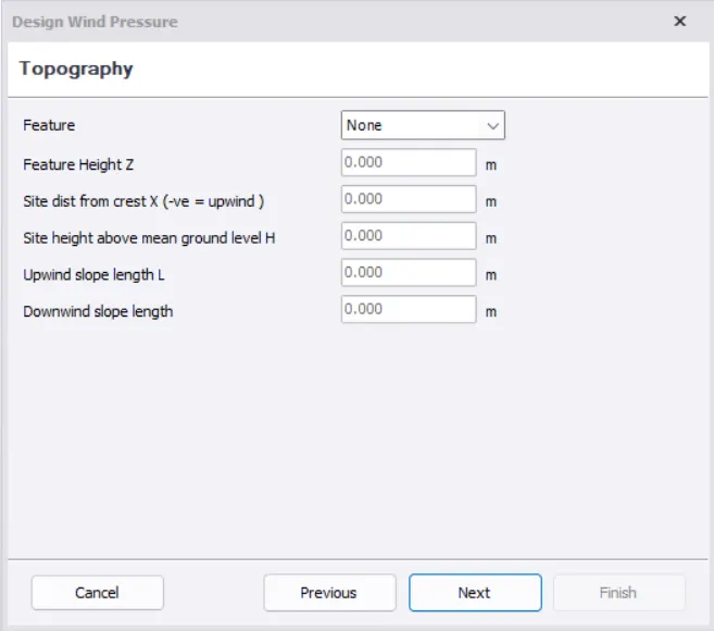
- Press Next
- Result will be default as software
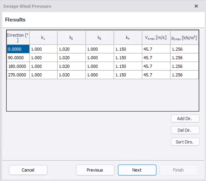
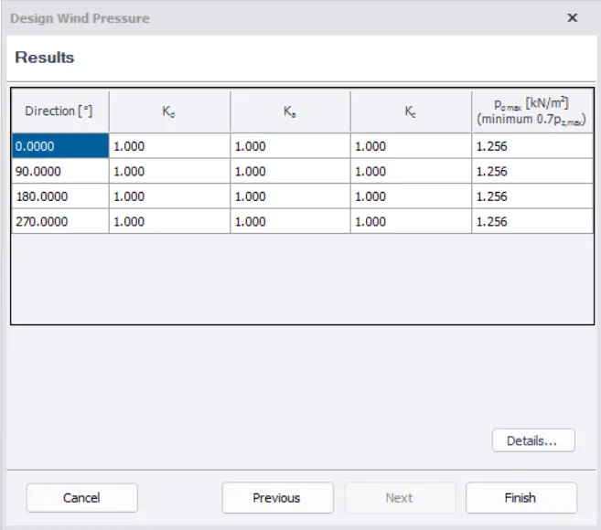
- Finish
- Then Go to Wind load case
- Here the Cpi Value wil change Direction:0 ,Cpi : 0.500
- Direction:0 ,Cpi : -0.500
- Direction:90 ,Cpi : 0.500
- Direction:90 ,Cpi : -0.500
- Direction:180 ,Cpi : 0.500
- Direction:180 ,Cpi : -0.500
- Direction:270 ,Cpi : 0.500
- Direction:270,Cpi : -0.500
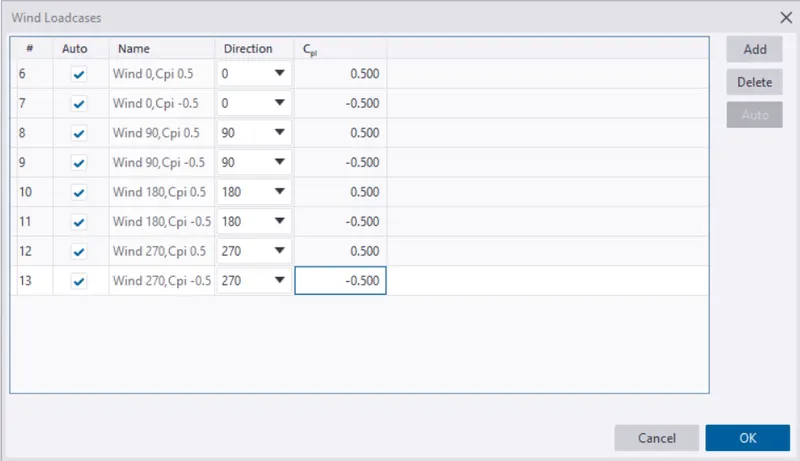
- Press Ok
Result: