To calculate wind load for industrial steel structures and to apply it by using TSD
1
Aim - To calculate thw wind loads manually by the given data by refering code
Procedure -
Basic wind speed - 39 m/s
Terrian category - 2
Max spacing - 7.2m
L (x) dist = 18
W (y) = 18.5
H = 12.5
Ratio of wall to roof
Wall (l/w) = 1
(h/w) = 0.67
Roof (h/w) = 0.67
Refer the values to table 5 (IS 875 P-3)
We will get Cpe values on the faces
Face A = 0.7
B = 0.25 ( away from structure)
C = 0.6 Away
D = 0.6 Away
Risk coefficient (K1) = 1 (Table 1 , 39 wind speed)
Wind speed variation with height (K2) = 1 (Table 2 up to height 10m)
Topography factor (K3) = 1 (C 5.3.3)
K4 = 1 (C-5.3.4)
Design wind pressure (Pz) = Vb+K1+K2+K3+K4
Pz = 39m/s
Design wind pressure Pz = 0.6 x Vz2 = 0.91Kn/m2
Roof angle = 27 degrees
Internal pressure coefficient Cpi = 0.50
-Cpi = -0.50 (C- 6.2.3.2 0-90)
Face A
+Cpi -Cpi
Cpi 0.5 -0.5
Cpe 0.7 0.7
Cp 0.2 1.2 (Cp = Cpe-Cpi)
Pz 1.2 1.2
Total wall pressure 0.24 1.44
Factored pressure 0.253 1.521 (pressurex1.05)
Face B
+Cpi -Cpi
Cpi 0.5 -0.5
Cpe 0.25 0.25
Cp -0.75 -0.75 (Cp = Cpe-Cpi)
Pz 1.2 1.2
Total wall pressure -0.905 0.30
Factored pressure -1.4 0.317 (pressurex1.05)
Because External pressure is same on face C and D so do both sare same pressures
Face C & D
+Cpi -Cpi
Cpi 0.5 -0.5
Cpe 0.6 0.6
Cp 0.1 1.1 (Cp = Cpe-Cpi)
Pz 1.2 1.2
Total wall pressure -1.328 -0.127
Factored pressure -1.4 -0.127 (pressurex1.05)
For ROOF EF
Y direction
Cpe = -0.12,0.4 for 27 degrees of roof and do interpolation
+Cpi -Cpi
Cpi 0.5 -0.5
Cpe -0.12 -0.4
Cp -0.62 0.1 (Cp = Cpe-Cpi)
Pz 1.2 1.2
Total wall pressure -0.74 0.12
Factored pressure -0.77 0.126 (pressurex1.05)
For ROOF GH
Y direction
Cpe = -0.12,0.4 for 27 degrees of roof and do interpolation for 20 and 30 for unknown
+Cpi -Cpi
Cpi 0.5 -0.5
Cpe -0.4 0.4
Cp -0.9 0.1 (Cp = Cpe-Cpi)
Pz 1.2 1.2
Total wall pressure -1.09 0.121
Factored pressure -1.14 0.12 (pressurex1.05)
For ROOF EF
X direction
Cpe = -0.6,+0.6 for 27 degrees of roof and do interpolation
+Cpi -Cpi
Cpi 0.5 -0.5
Cpe -0.6 0.6
Cp -1.1 -0.1 (Cp = Cpe-Cpi)
Pz 1.2 1.2
Total wall pressure -1.32 -0.12
Factored pressure -1.38 -0.126 (pressurex1.05)
For ROOF GH
X direction
Cpe = -0.7,0.7 for 27 degrees of roof and do interpolation
+Cpi -Cpi
Cpi 0.5 -0.5
Cpe -0.7 0.7
Cp -1.2 0.2 (Cp = Cpe-Cpi)
Pz 1.2 1.2
Total wall pressure -1.44 0.24
Factored pressure -1.16 0.25 (pressurex1.05)
2
Aim - Based on the above valuves we got apply on the model in tekla
Procedure
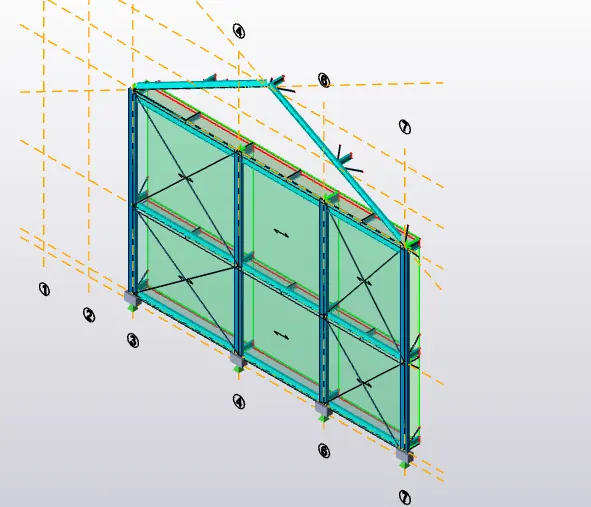
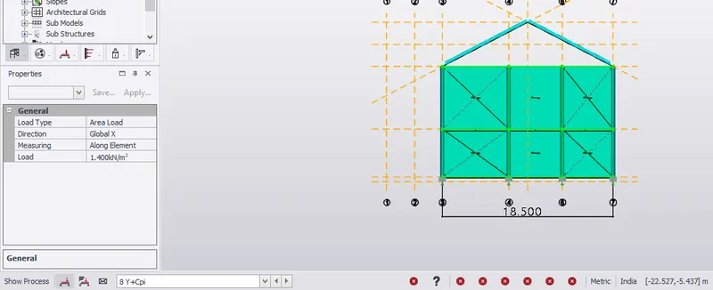
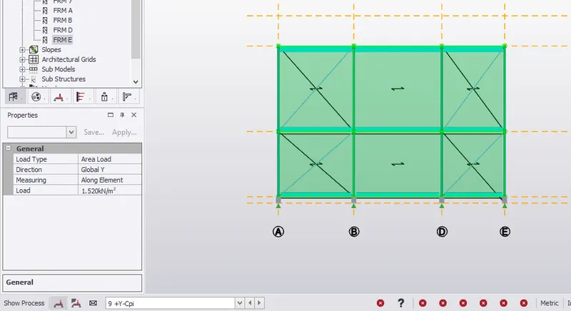
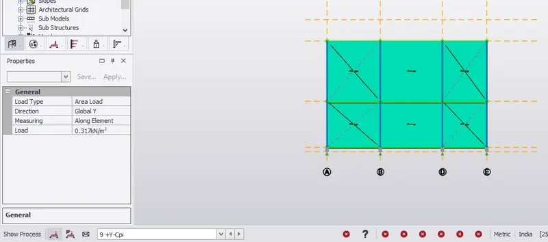
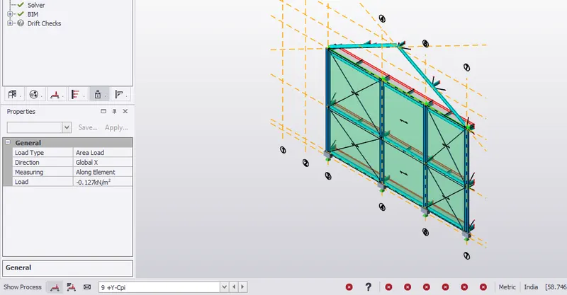
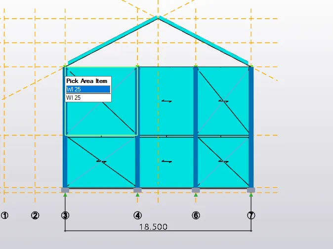
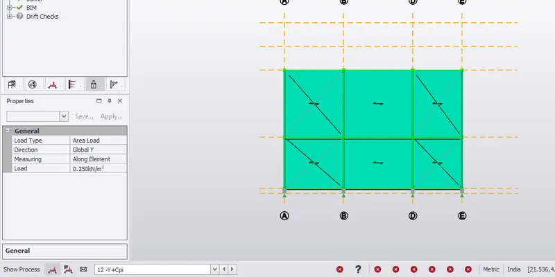
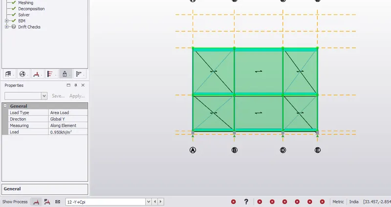
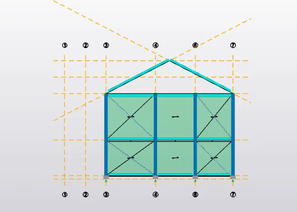
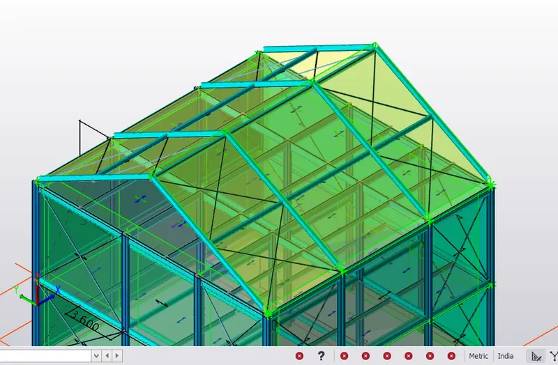
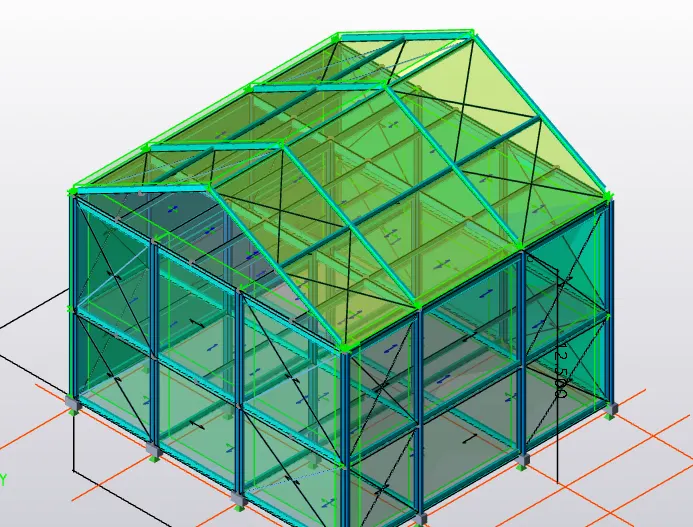
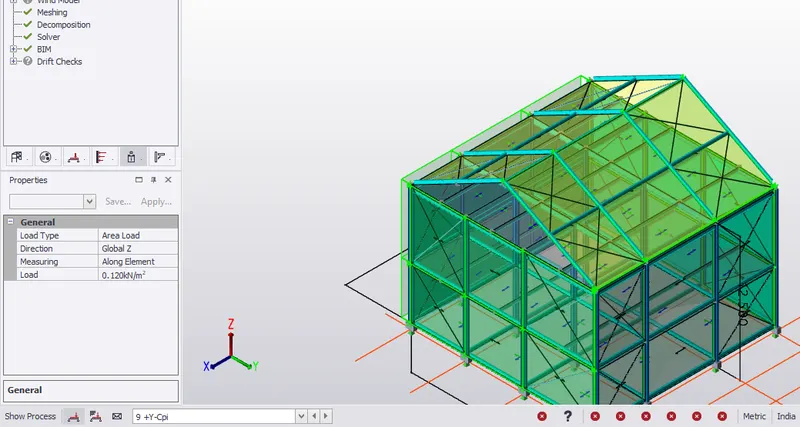
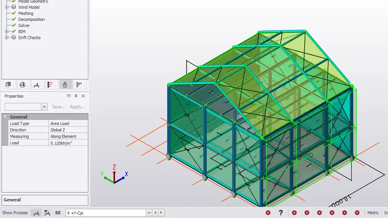
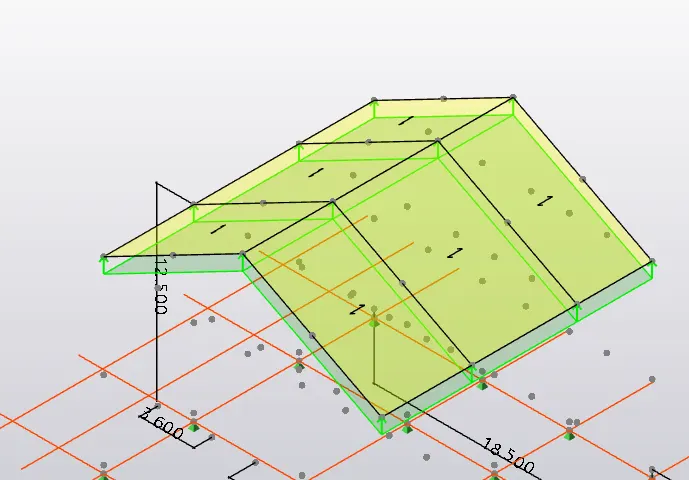
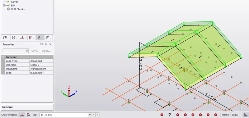
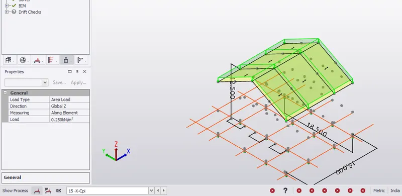
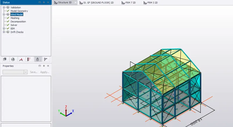
Apply wond loads on the model
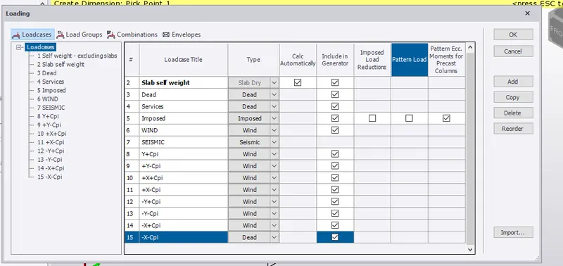
First create load cases
Give wind type for all the loads
+Y+Cpi
+Y-Cpi
+X-Cpi
+X+Cpi
-Y+Cpi
-Y-Cpi
-X+Cpi
-X-Cpi
Select wind load case from the bar
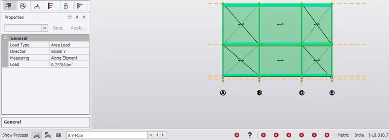
Wind +Y+Cpi
Select he frame
On the side A
On the load tab select area
Give global Y direction
Give load as 0.24 and select all the panels on side A
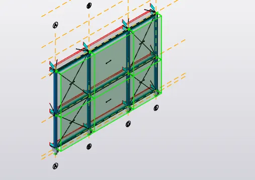
Check weather loads applied on not in 3D
Select wind load case from the bar
Wind +Y+Cpi
Select he frame
On the side B
On the load tab select area
Give global Y direction
Give load as -0.950 and select all the panels on side A
Check weather loads applied on not in 3D
Select wind load case from the bar
Wind +Y+Cpi
Select he frame
On the side C&D
On the load tab select area
Give global X direction
Give load as -1.4 and select all the panels on side C&D
Check weather loads applied on not in 3D
Select wind load case from the bar
Wind +Y-Cpi
Select he frame
On the side A
On the load tab select area
Give global Y direction
Give load as 1.52 and select all the panels on side A
Check weather loads applied on not in 3D
Select wind load case from the bar
Wind +Y-Cpi
Select he frame
On the side B
On the load tab select area
Give global Y direction
Give load as 0.31 and select all the panels on side B
Check weather loads applied on not in 3D
Select wind load case from the bar
Wind +Y-Cpi
Select he frame
On the side C&D
On the load tab select area
Give global X direction
Give load as -0.127 and select all the panels on side C&D
Check weather loads applied on not in 3D
For load case
-Y+Cpi and -Y-Cpi
Inter change the faces any apply the same loads
A as B and B as A
C as D and D as C
Add load for the roof now as Global Z
Y direction
Select load case as +Y+Cpi of FH
Give area load of -0.77 on one side
Then selecct y-Cpi
Then give areal load of -1.14 on other side
Then -Y+Cpi and -Y+Cpi and interchange the sides on the roofs
Then in X direction
Select +X load case of X+Cpi
Give load of -1.38 and -1.16 on the either sides
Then X-Cpi
Give area load of -0.126 snd 0.25 on teh oppsite either side
The load case of -X+Cpi and -X-Cpi interchange the directions
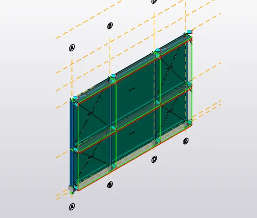
Chek all the loads in the 3D
Validate the model in every interval
3
Aim - Generate wind loading by the wind wizard
Procedure
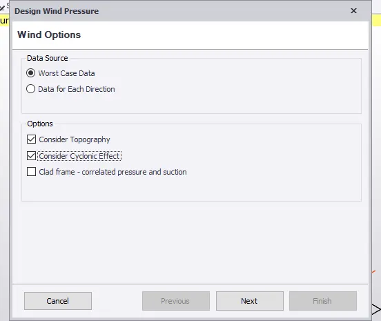
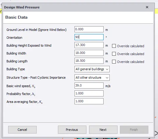
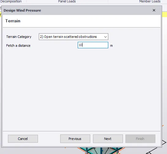
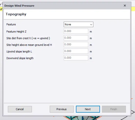
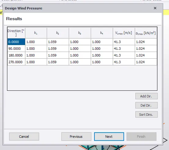
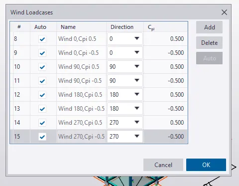
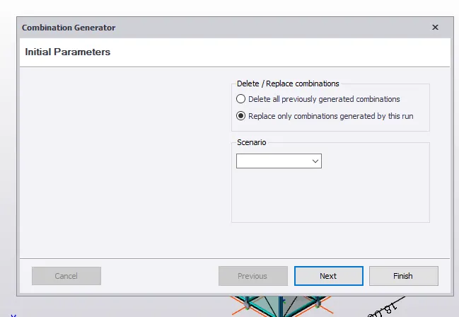
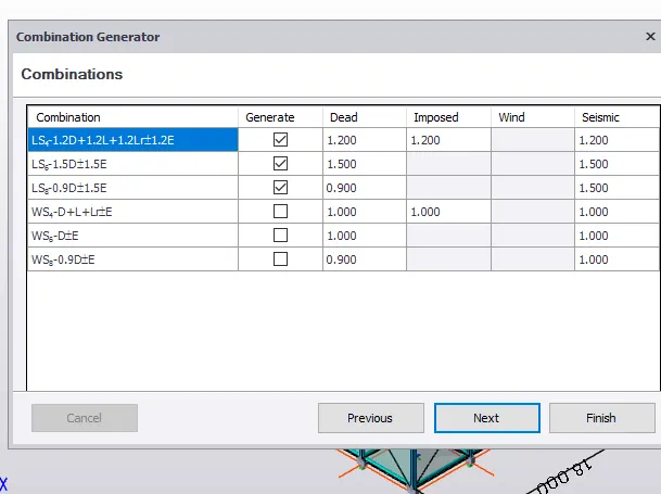
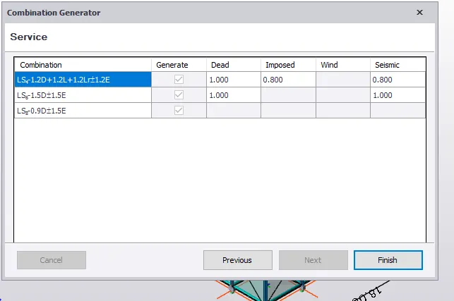
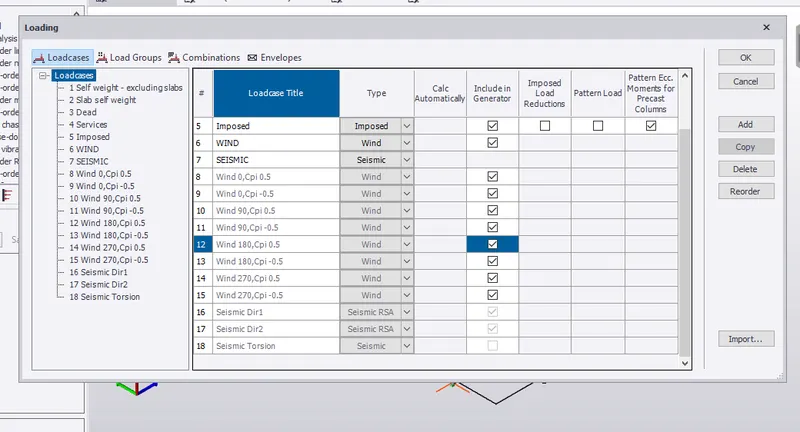
As we added wind loads
Then delete all the wind load cases
Now generate wind loading by wind wizard
In the load tab select wind wizard
Click tick mark on topography and cyclonic effectThen next
Give heights of the building
Type as all genetal , structure as industrial and terrian capacity as 2
Then fetch distance of 10 and next
Topo table and next
Results displayed then Next
Add the wind load cases
Give direction and Cpi valude at 0,90,180 and 360
Then give Cpi values as -0.5 and +0.5 for all directions
OK
All the wind panels should be in one direction
Check the load case wind loads are generted
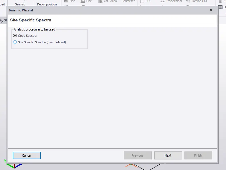
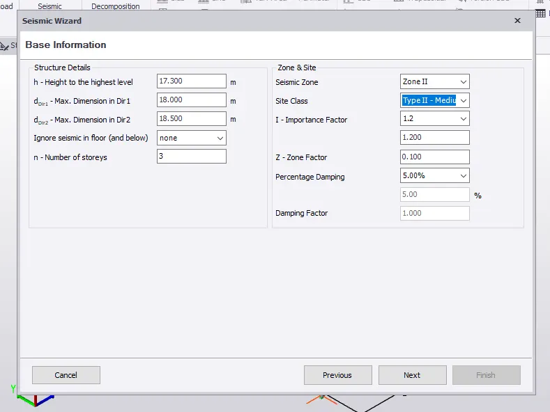
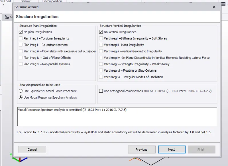
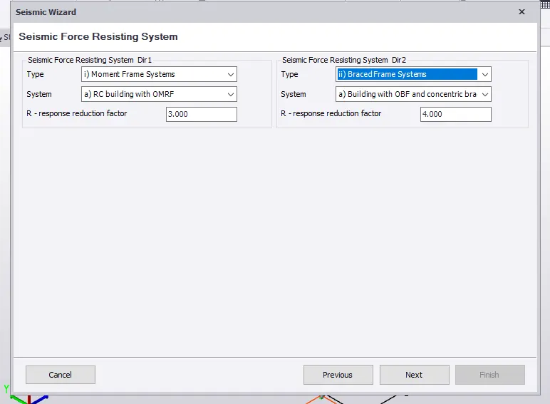
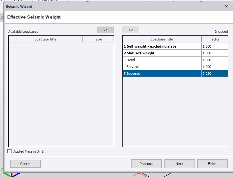
Seismic loads can also be generated in the same way
In the seisnic load tab