To calculate the dead , live and wind load for RC residential structure and to apply them using TSD
1
Aim - To calculate the dead loads and apply on the model created
Procedure
Dead loads
Finishers as given 0.05m
0.05m x 24Kn/m2(density)
=1.2Kn/m
Brick wall load
Wall thickness 1540mm
For ground floor height is 5.5m
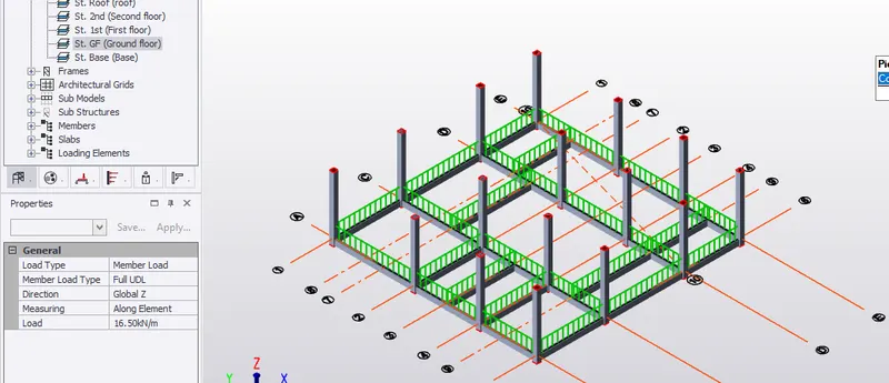
20x0.150x5.5
= 16.5Kn/m
For first floor
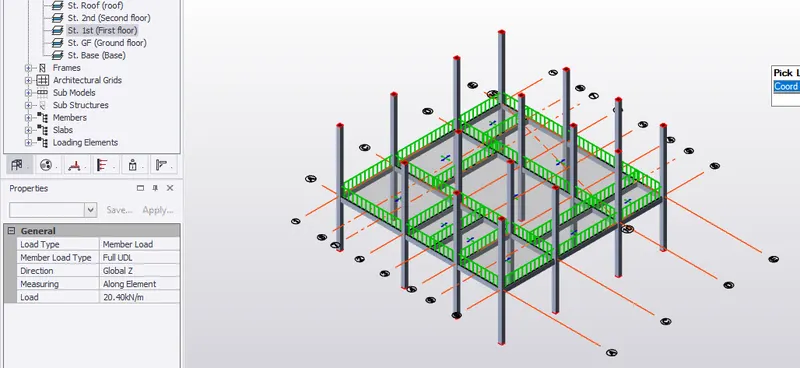
height is 6.8m
Then load is = 20.4Kn/m
Slab load is calculated by the software
Ceiling is 0.3Kn/m
DEAD LOADS
Then loads
In the load cases in the loads tab
See weather all the loads are there are not if not add new as wind and type as wind
Seismic as seismic type
Then go to load combo
Generate new load combo
Table then see all the load combos and next and finish
If you want to add new combo add new
Dead loads are already calculated
Self weight is calculated by software itself
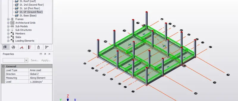
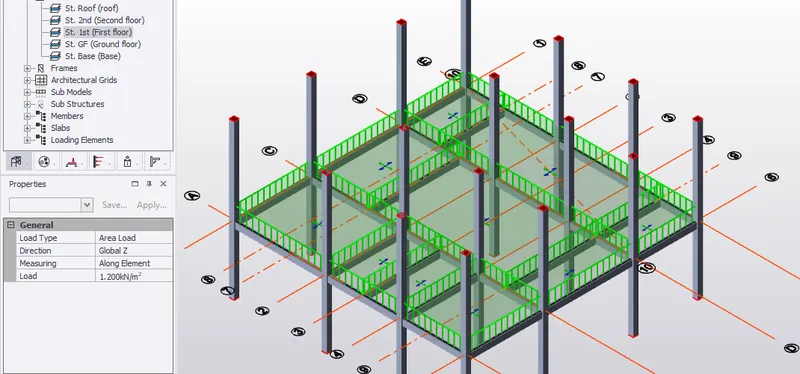
Finishers loads
1.2 KN/m2
Select dead in the bottom left bar
Then add area load give value as 1.2
Select all the slabs it will add the loads
Check in 3d
Do in all the floors
Wall loads
Ground floor
16.5 KN/m2
Select dead in the bottom left bar
Then add line load give value as 16.5
Select all the beams it will add the loads
Check in 3d
First floor
20.4 KN/m2
Select dead in the bottom left bar
Then add line load give value as 20.4
Select all the beams it will add the loads
Check in 3d
Roof loads
Switch on roof panel
Area load and give load as 1.5
Start applying on teh roof
Validate in every interval and rectify errors
2
Aim - To calculate the live loads and apply on the model created
Procedure
LIVE LOADS
According to the code apply the live loads
In the balcoly and lounge 3Kn/m2
All the remaining rooms 3KN/m2
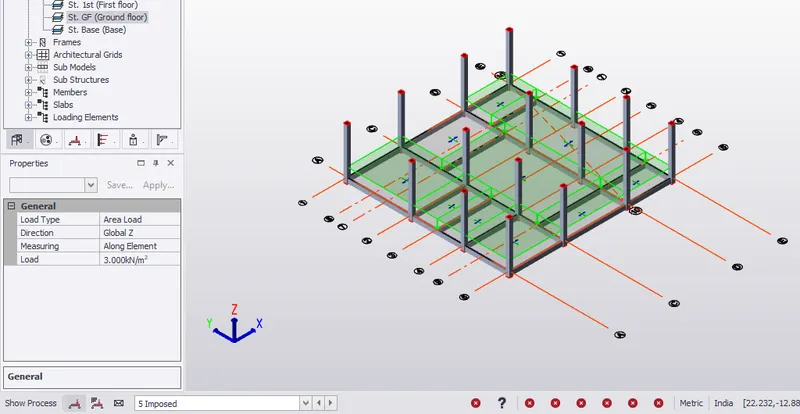
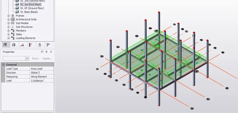
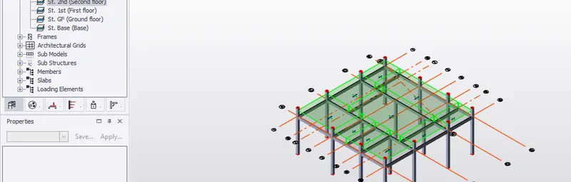
Change load cases to imposed
Give area load and give loads according to is876
Give loads in all the rooms as 3 and 5 KN/m2
In all the floors do the same as we done before
For roof add 1.5 because it is accesible according to code
Validate in every interval
3
Aim - To calculate thw wind loads manually by the given data by refering code
Procedure -
Basic wind speed - 50 m/s
Terrian category - 2
Max spacing - 7.2m
L (x) dist = 18
W (y) = 18.5
H = 12.5
Ratio of wall to roof
Wall (l/w) = 1
(h/w) = 0.67
Roof (h/w) = 0.67
Refer the values to table 5 (IS 875 P-3)
We will get Cpe values on the faces
Face A = 0.7
B = 0.6 ( away from structure)
C = 0.6 Away
D = 0.6 Away
Risk coefficient (K1) = 1 (Table 1 , 39 wind speed)
Wind speed variation with height (K2) = 1 (Table 2 up to height 10m)
Topography factor (K3) = 1 (C 5.3.3)
K4 = 1 (C-5.3.4)
Design wind pressure (Pz) = Vb+K1+K2+K3+K4
Pz = 57.5m/s
Design wind pressure Pz = 0.6 x Vz2 = 0.91Kn/m2
Roof angle = 0 degrees
Internal pressure coefficient Cpi = 0.6
-Cpi = -0.6 (C- 6.2.3.2 0-90)
Face A
+Cpi -Cpi
Cpi 0.6 -0.6
Cpe 0.7 0.7
Cp 0.1 1.3 (Cp = Cpe-Cpi)
Pz 2 2
Total wall pressure 0.2 2.6
Factored pressure 0.21 2.73 (pressurex1.05)
Face B
+Cpi -Cpi
Cpi 0.6 -0.6
Cpe 0.6 0.6
Cp 0 1.2 (Cp = Cpe-Cpi)
Pz 2 2
Total wall pressure 0 2.4
Factored pressure 0 2.52 (pressurex1.05)
Because External pressure is same on face C and D so do both sare same pressures
Face C & D
+Cpi -Cpi
Cpi 0.6 -0.6
Cpe 0.6 - 0.6
Cp 0 -1.2 (Cp = Cpe-Cpi)
Pz 2 2
Total wall pressure 0 -2.4
Factored pressure 0 -2.52 (pressurex1.05)
For ROOF EF
Y direction
+Cpi -Cpi
Cpi -0.8 -0.6
Cpe 0.6 -0.6
Cp 0.2 -1.2 (Cp = Cpe-Cpi)
Pz 2 2
Total wall pressure -0.4 -2.4
Factored pressure -0.42 -2.52 (pressurex1.05)
For ROOF GH
Y direction
+Cpi -Cpi
Cpi -1.0 -0.6
Cpe 0.6 -0.6
Cp -0.4 -1.2 (Cp = Cpe-Cpi)
Pz 2 2
Total wall pressure -0.8 -4
Factored pressure -0.84 -4.2 (pressurex1.05)
4
Aim - Based on the above we have got apply all the loads on the model
Procedure
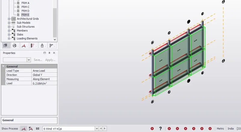
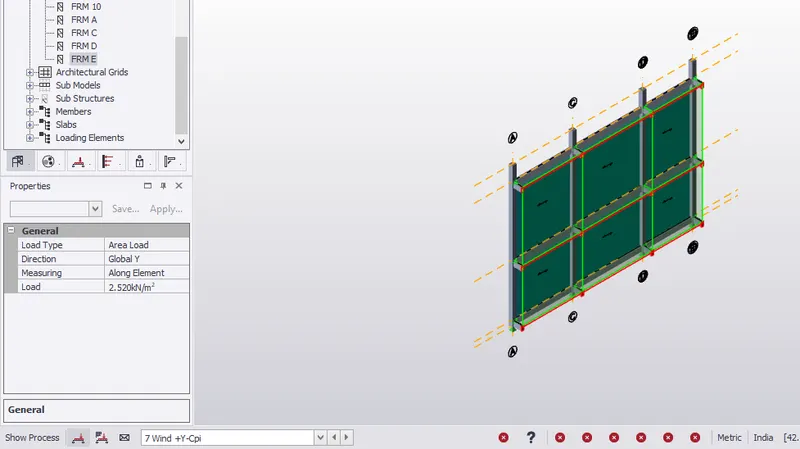
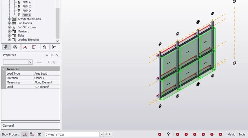
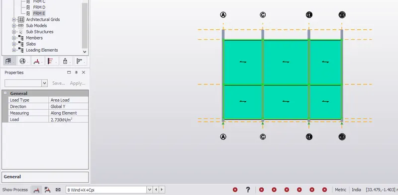
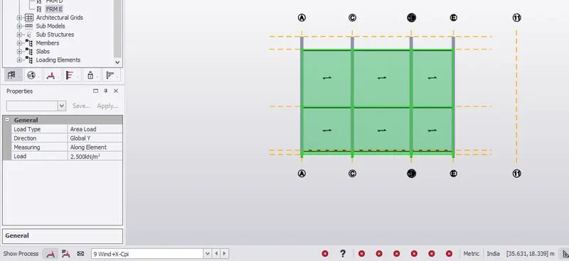
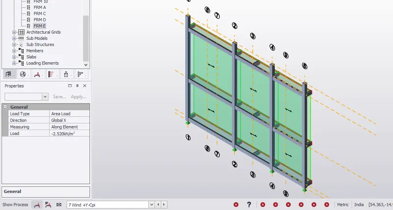
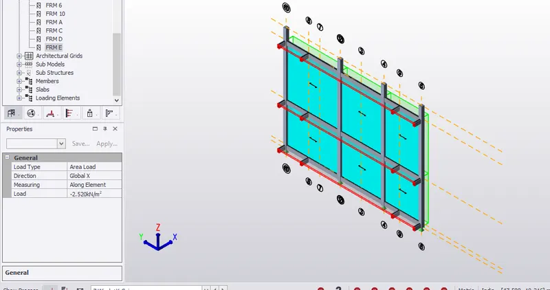
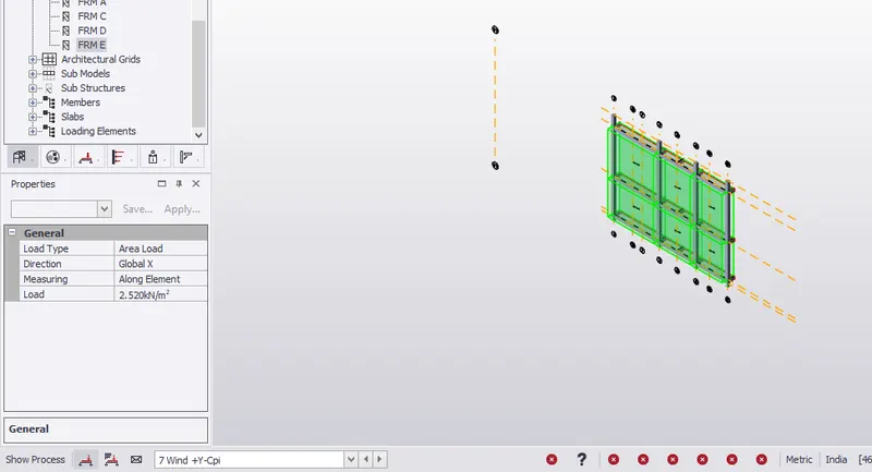
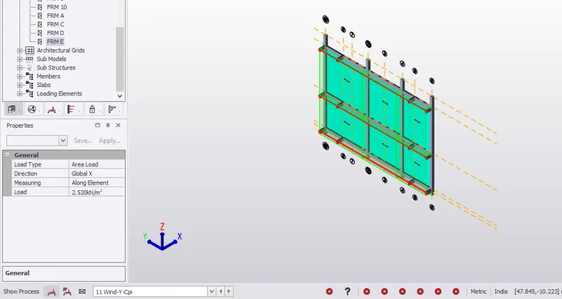
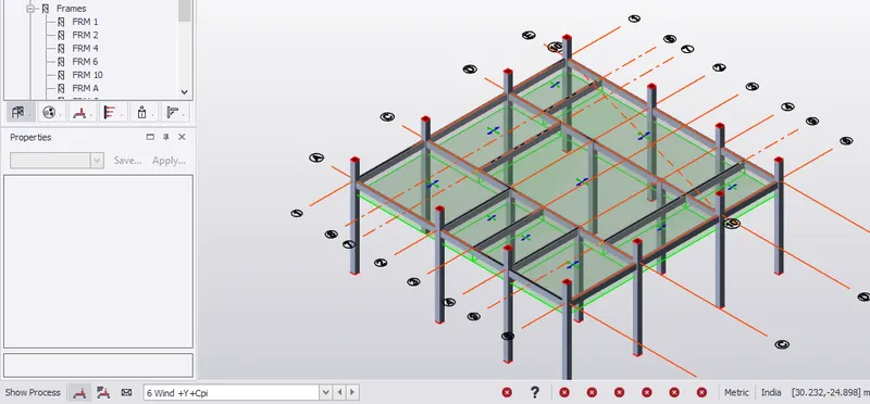
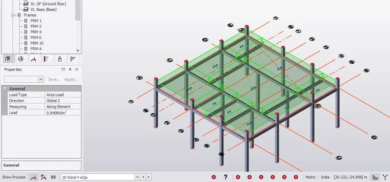
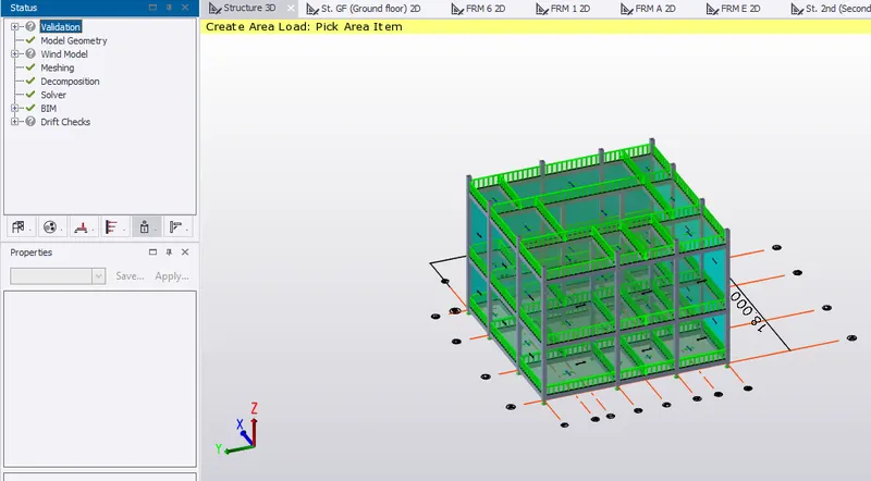
Apply wind loads on the model
First create load cases
Give wind type for all the loads
+Y+Cpi
+Y-Cpi
+X-Cpi
+X+Cpi
-Y+Cpi
-Y-Cpi
-X+Cpi
-X-Cpi
Select wind load case from the bar
Wind +Y+Cpi
Select he frame
On the side A
On the load tab select area
Give global Y direction
Give load as 0.211 and select all the panels on side A
Check weather loads applied on not in 3D
Select wind load case from the bar
Wind +Y+Cpi
Select he frame
On the side B
On the load tab select area
Give global Y direction
Give load as0 and select all the panels on side A
Check weather loads applied on not in 3D
Select wind load case from the bar
Wind +Y+Cpi
Select he frame
On the side C&D
On the load tab select area
Give global X direction
Give load as 0 and select all the panels on side C&D
Check weather loads applied on not in 3D
Select wind load case from the bar
Wind +Y-Cpi
Select he frame
On the side A
On the load tab select area
Give global Y direction
Give load as 2.73 and select all the panels on side A
Check weather loads applied on not in 3D
Select wind load case from the bar
Wind +Y-Cpi
Select he frame
On the side B
On the load tab select area
Give global Y direction
Give load as 2.52 and select all the panels on side B
Check weather loads applied on not in 3D
Select wind load case from the bar
Wind +Y-Cpi
Select he frame
On the side C&D
On the load tab select area
Give global X direction
Give load as -2.52 and select all the panels on side C&D
Check weather loads applied on not in 3D
For load case
-Y+Cpi and -Y-Cpi
Inter change the faces any apply the same loads
A as B and B as A
C as D and D as C
Add load for the roof now as Global Z
Y direction
Select load case as +Y+Cpi of FH
Give area load of -0.42 on one side
Then selecct y-Cpi
Then give areal load of -2.52 on other side
Then -Y+Cpi and -Y+Cpi and interchange the sides on the roofs
Then in X direction
Select +X load case of X+Cpi
Give load of -0.84 and -4.2 on the either sides
Then X-Cpi
Give area load of -0.42 snd -2.52 on teh oppsite either side
The load case of -X+Cpi and -X-Cpi interchange the directions
Chek all the loads in the 3D
Validate the model in every interval