To calculate the dead , live and wind load for RC residential structure and to apply them using TSD
- AIM: To calculate the dead load in design based on IS code and apply on the model
- Tools used : Load cases ,Full UDL , Area load ,Property window\
- Calculation :
- Slab model
- Finishes Loading = 0.05 X 24 KN/M^2 =1.2 KN/m^2
- Brick Wall with cement plaster thickness = 225mm
- Unit weight = 20KN/m^2
- Floor Height = 3.6 m
- Brick Wall Loading = 225 X 20 X 3.6 /1000 = 16.2 KN/m
- Roof Wall Loading = 1.5 KN/m
- PROCEDURE
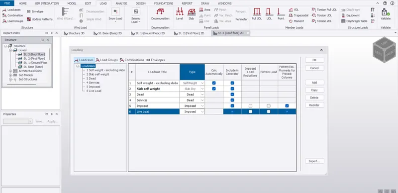
- Click on load cases in the load tab and check if there is dead load created ,If not created then create load cases named as dead load by
- Clicking on add option
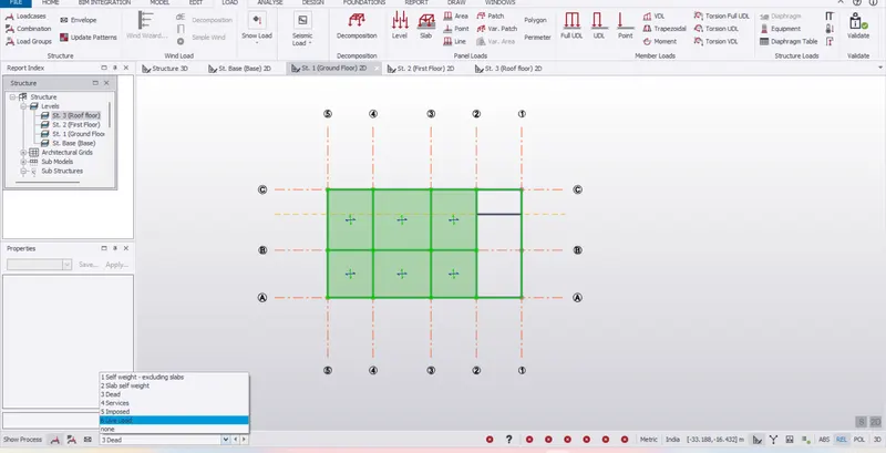
- In the left bottom corner ,Select dead load in the dead load case drop down
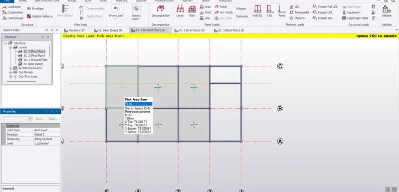
- Click on area load in the load tab and enter the direction as global Z and value of load as 1.2 KN/m and select all the slabs for applying the slab loading
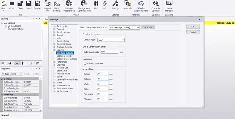
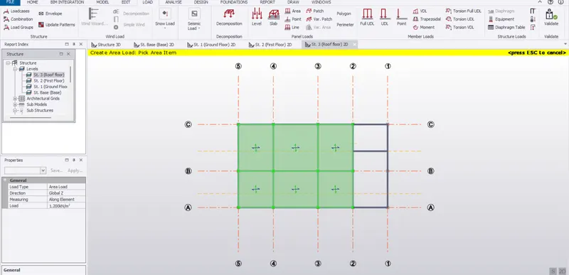
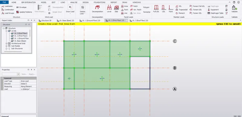
- Then click on UDL in the load tab and enter the value as 16.2 KN/m for the ground floor and first floor and select the beam lines and extra walls accordiing to the plan
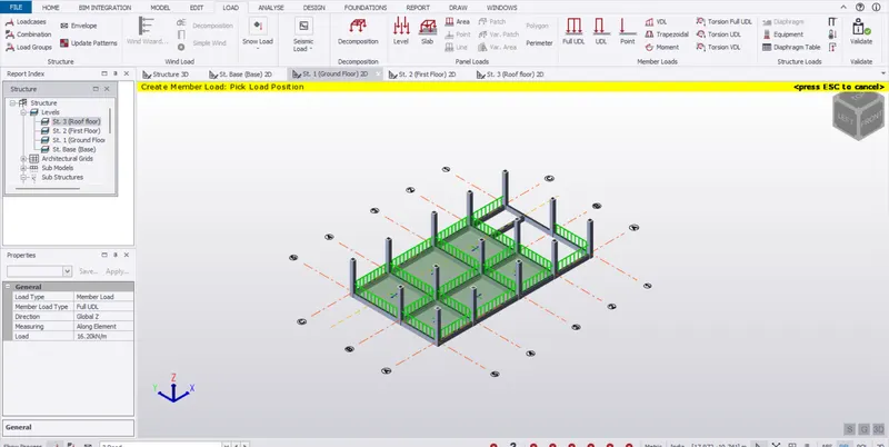
- Again click on full UDL and enter the value as 1.5 KN/m for the roof floor walls
- AIM : To calculate the live load in design report based on IS code and apply it on model
- Tools used : Load cases , Live load ,area load , Property window
- Calculation
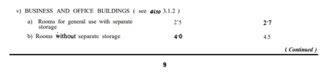
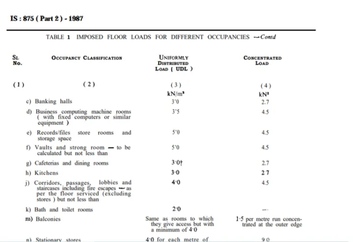
- Live loads of diffrent type of rooms is to e taken as IS 875 Part 2
- PROCDEDURE
- Click on load cases and a create load case named as live load and select the lopad type as imposed in the load type and dropdown and click OK
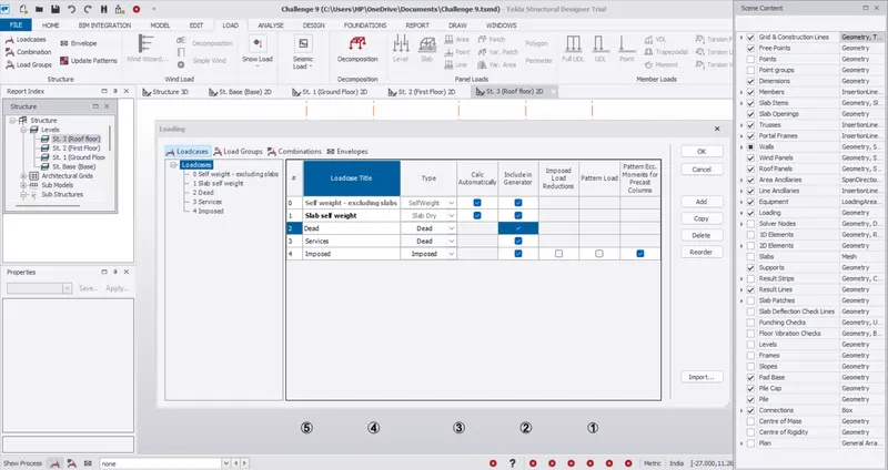
- In the left bottom corner , In the load cases dropdown and select the load case as live load
- Click on area load in the load tab.Enter the value of loading as per the plan given in the attachements for ground floor and first floor
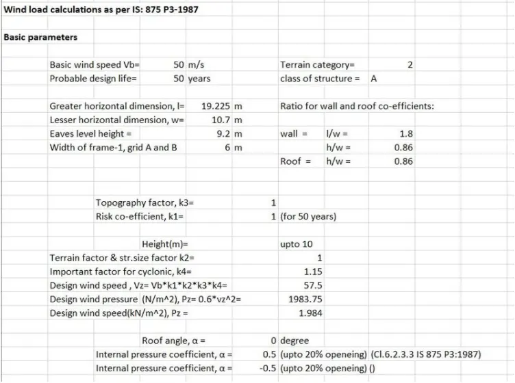
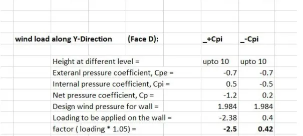
- AIM : Generate manual wind loading in design report based on IS code with given input
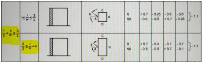
- Calculation :
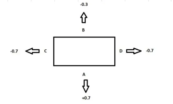
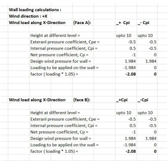
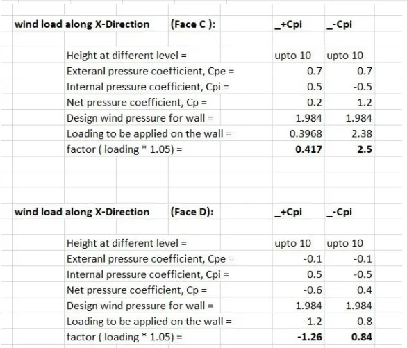
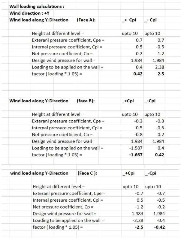
- AIM : To apply wind load calculation on the model
- PROCEDURE :
- Click on frames in the model tab and create frames for outer wall of the structure
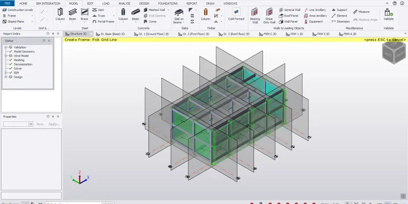
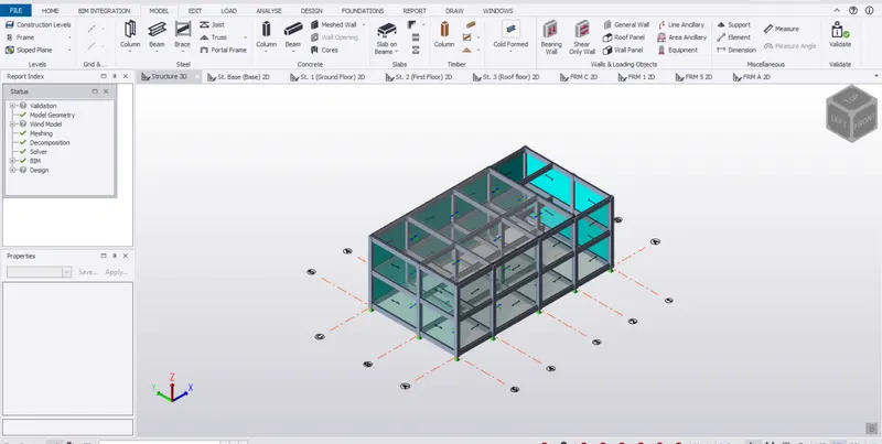
- Open frame using frame using structure window and click on wall panels in the model tab and create wall panels in all frames
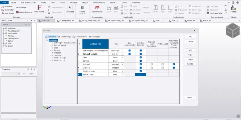
- Now click on load cases in the load tab add new load cases and name them as wind load +Y +Cpi,wind load -Y-Cpi and select the type as wind load and click OK
- Open frame C which is considered as wall A and apply wind load +Y-Cpi, wind load +Y-Cpi as per calculation shown above on clicking on area load and setting direction as global +Y and entering the value as 0.42 and 2.5 resp.
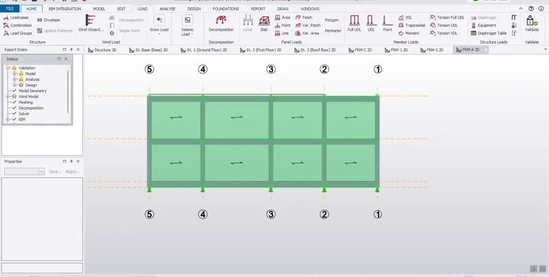
- Repeat frame A which is wall B and frame 5 which is wall C and frame 1 which is wall D set direction as global X for walls C and D
- RESULT :
- Wind load applied on walls of structure