To calculate dead and live load for industrial steel structures and to apply them using TSD
QUESTION:1
1Calculate dead load in design report based on IS code and apply dead load on the model
- Finishes of 50mm
- Slab as per design
- Brickwall 150mm thickness
- Roofing load based on purlin size
- Ceiling loading 0f 0.3KN per sq m
ANSWER:
AIM: To calculate dead load in design report based on IS code and apply dead load on the model.
INTRODUCTION:
A constant load in a structure that is due to the weight of the members, the supported structure, and permanent attachments.It is a static load of the bulding such as self weight of the columns,beams and slabs.
It also includes brickwall weight,floor finish,ceiling weight etc.,
PROCEDURE:
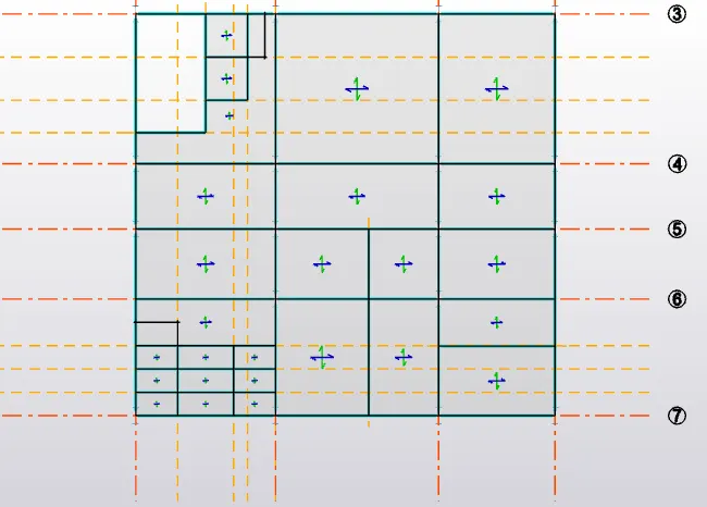
- initially define a slab property and model them for ground floor,intermediate foor and roof floor.
- consider one-way or two-way slab based on the x/y ratio.
- thickness of slab for groundfloor and intermediate floor is 150kN/m and that of roof floor is 125kN/m.
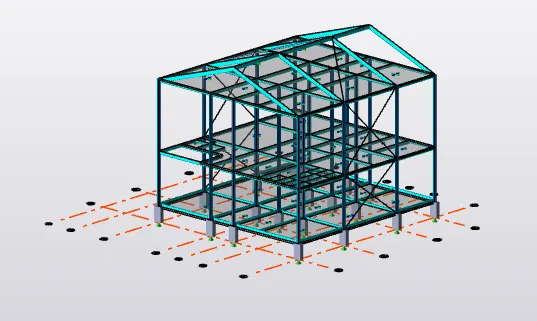
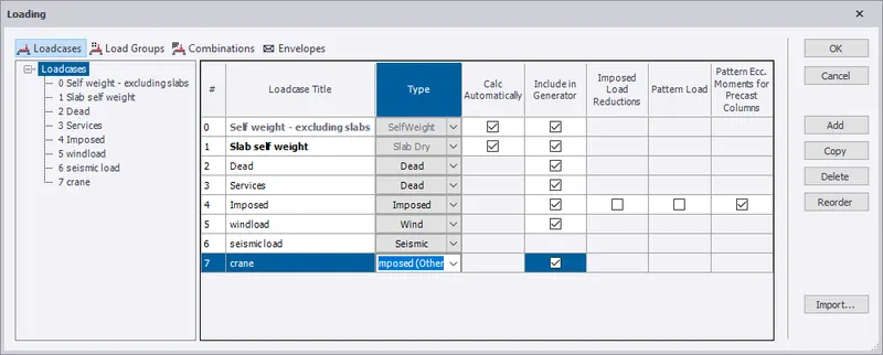
- define addtitional load such as seismic load,wind loadetc under load cases.
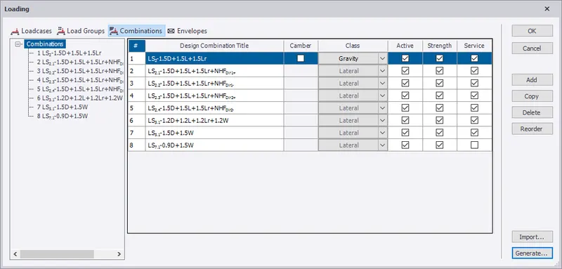
- select load combination>generate load ,new ocmbination is automatucaly generated.
dead load calculation- as per IS 875:part 1
unit weight fo concrete=24kN/m3
finish loading=0.05x24=1.2kN/m2
brick wall loading of 1150mm,unit weight =20kN/m3
brick wall loading(GF-IF)=0.15*20*5.2=15.6kN/m
brickwall loading(IF-R)=0.15*20*6.8=20.4kN/m
self weight of the slab is calculated by software itself
roof loading based on purlin size=1.5kN/m2
ceiling loading=0.3kN/m2
- select dead load>load toolbar>area load>1.2>click on slabs for finish load.
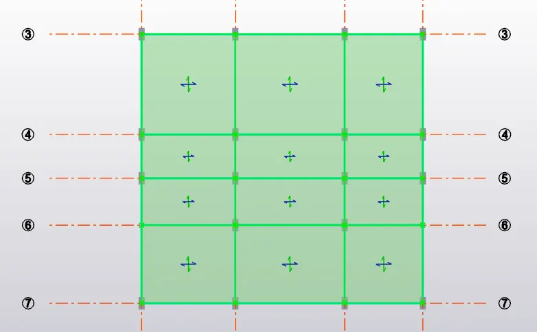
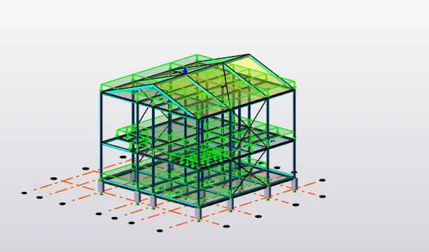
- dead load>load toolbar>full udl>enter 15.6 for GL-IL>click on beams.
- for birckwall load inside select line load and add.
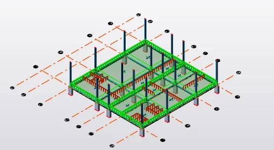
- repeat the same for IL-RF(20.4)
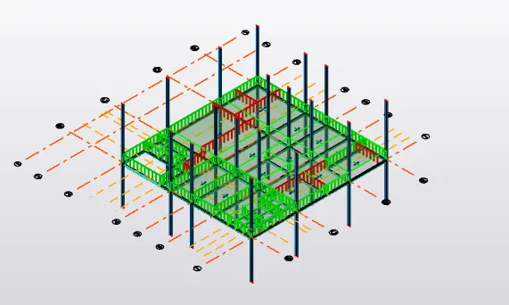
- go to 3d strcuture and select dead load at bottom,area load from load toolbar(1.5) and same or ceiling load.
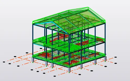
validate at each step for error check,if no error proceed.
RESULT: dead load(finish lod and brickwall load) is calculated manually and applied on the structure.
QUESTION:-2
Calculate live load in design report based on IS code and apply live load on the model
- Assume the loading based on IS 875
- Roof loading
- Consider equipment loading as 5KN per sq m
ANSWER:
AIM: To calculate live load in design report based on IS code and apply live load on the model
INTRODUCTION:
live load is referred to a load that can change over time. The weight of the load is variable or shifts locations, such as when people are walking around in a building. Anything in a building that is not fixed to the structure can result in a live load, since it can be moved around.
PROCEDURE:
live load as per IS 875:Part 2 is
- Stair case = 5KN/m2
- Workshop = 5 KN/m2 ( Considering Light Machinery)
- Corridor = 5KN/m2
- Meeting Room =5 KN/m2
- Store room = 5 KN/m2
- Toilet=2 KN/m2
- Canteen 3 KN/m2
- Office = 3KN/m2
- Conference = 5KN/m2
- Equipment = 10KN/m2
- Administration room -5KN/m2
- roof load for on accessible-0.75kN/m2
set the ground floor level>load toolbar>area loading and value as per IS code.
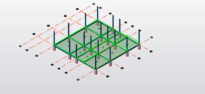
simialry repeat the same for intermediate floor and roof floor.
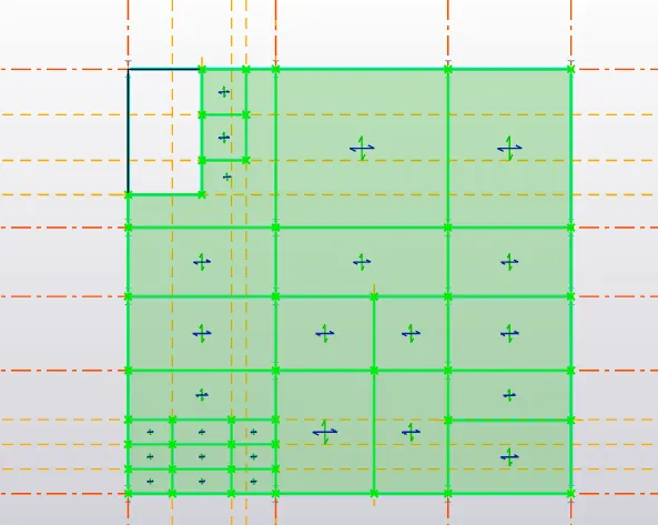
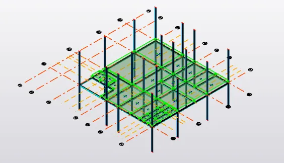
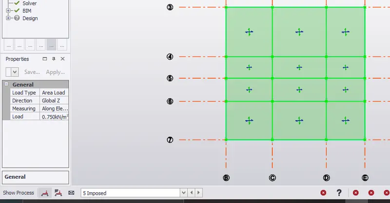
validate at each step for error check,if no error proceed.
RESULT: Live load as per code ia noted down and applied on the structure.
QUESTION:-3
Generate a calculation for 5T crane loading based on following inputs
- Centre to Centre of wheel = 10m
- Weight of crab = 40 KN
- Number of wheels = 4
- Wheel base = 2m
ANSWER:
AIM: To generate a calculation for 5T crane loading based on the following inputs.
- Centre to Centre of wheel = 10m
- Weight of crab = 40 KN
- Number of wheels = 4
- Wheelbase = 2m
calculation:
Max wheel load
Maximum concentrated load on crane = 50 + 10 = 60 KN.
Self-weight of crane will act as uniformly distributed load of intensity
=40 / 10 = 4 KN/m.
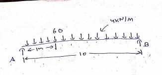
consider moment about B :
(Ra x 10) = (60 x 9)+(4 x 10/2 x 10) =540+200=740
10 Ra = 740.
Ra = 74 KN.
sum of y components = 0
Ra + Rb =60+ 4(10)
74+Rb=100
Rb=26 KN
The reaction from the crane girder is distributed equally on two wheels at the end of the crane girder.
Maximum wheel load on each of the crane wheel = 74 / 2 = 37KN.
MAXIMUM BENDING MOMENT :
let us Assume the self-weight of the gantry girder as 1.5 KN/m
Total dead load = ( Self-weight of rail + self-weight of gantry girder ) 300 + 1500 = 1800 N/m
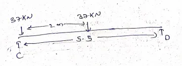
consider moment about D
Rc x 5.5 =(37 x 4.25)+(37 x 2.25)
Rc x 5.5 = 157.25+83.25=240.5
Rc = 240.5 / 5.5= 43.72 KN.
sigma y =0
Rc+Rd=37+37=74
Rd=74-43.72 = 30.27 KN.
Rd=30.27 KN
Bending moment under wheel due to live load = Rd x 2
= 30.27 x 2
= 60.54 KNM.
Bending moment due to impact = 10/100 x 60.54 ( 10 % increase due to MOT)
= 6.054 KNM
Total bending moment due to live load and impact load = 60.54 + 6.054
= 66.594 KNM.
Bending moment due to dead load = W x l x l / 2
= 1.8 x 5.5 x 5.5 / 2 = 27.225 KNM
Maximum bending moment = 66.594 + 27.225
= 93.819 KNm.
MAXIMUM SHEAR FORCE :
For maximum shear force, one of
Rc x 5.5 –(37 x 5.5)-(37 x 2.5) = 0
Rc = 9.25 + 20.35 / 5.5
Rc = 5.381 KN
The maximum shear force due to wheel load = 5.381 KN
LATERAL FORCES :
Lateral forces traverse to rails = 5% of the weight of crab and weight lifted
=5/100( 40 + 10 )
= 2.5KN
Lateral forces on each side wheel F1 = 2.5 / 2 = 1.25 KN
Maximum horizontal reaction due to the lateral force by proportion at C
= Lateral force x reaction at C due to vertical load / maximum wheel load due to vertical load
= 1.25 x ( 43.72 / 37) = 1.44 KN
At D
2.5 – 1.44 = 1.06 KN
Bending moment due to lateral load by proportion
= (1.25 / 37) x 5.31
= 0.179 KNm.
RESULT:
WE HAVE GENERATED CALCULATION FOR 5T CRANE LOADING BASED ON THE GIVEN INPUTS
- Centre to Centre of wheel = 10m
- Weight of crab = 40 KN
- Number of wheels = 4
- Wheelbase = 2m
AND GOT THE RESULTS AS FOLLOWS
Ra = 74 KN
Rb=26 KN
Maximum bending moment =93.819 KNM.
The maximum shear force due to wheel load = 5.381 KN
Lateral forces on each side wheel F1 = 2.5 / 2 = 1.25 KN
Bending moment due to lateral load by proportion = 0.179 KNm.