Drafting of various geometries using Chamfer, Fillet tool in AutoCad
Drafting of various geometries using Chamfer,Fillet tool in AutoCAD.
AIM:
Drafting of various geometries using Chamfer,Fillet tool in AutoCAD.
INTRODUCTION:
- AutoCAD consist of a number of drawing and modification tools.Among the modification tools are the Chamfer,Fillet,Offset,Object,Snap,Rotate,Copy,Move,Mirror,Trim,Extend,and Join.
- CHAMFER:
- A bevel or chamfer is an angled line that meets the endpoint of two strating 2d points .a slope transition between two surfaces or adjacent faces on a 3D solid.
- The distance and angles that we specify are applied in the order that we select the objects.
2.FILLET:
- Around or fillt is an arc that is created as a tangent between 2D objects.Acurved transition between two surface or adjacent faces on a 3D solid.
3. OFFSET:
- It is used to create concentric circles ,parallel lines and parallel curves.
4. OBJECT SNAP:
- Object snap provides a way to specify precise location,such as end point ,midpoint etc.on objects whenever we are prompted for a point within a command.We can offset an object at a specified distance or through a point.
5.ROTATE:
- This tool rotates objects around a base point. An object can be rotated either by entering the angle of rotation,or drag the object around its base point and specifying a point location to which we want to rotate the object.we can also enter cto create a copy of the selected object from a specified reference angle to an absolute angle.
6.COPY:
- This command copies objectes at a specified distance in a specified direction .with the copy mode system variable,we can control whether multiple copies are to be created automatically.
7.MOVE:
- It moves object a specified distance in a specified direction.we can use coordinate ,grid snap,object snaps and other tools to move objects with precision.
8. MIRROR:
- This command is used to create a mirrored copy of selected objects.using this command we can create objects that represent half of a drawing,select them,and mirror them across a specified line to create the other half.
9. TRIM:
- It trims extends objects to meet the edges of other objects.There are two modes that can be used to trim objects viz quick mode and standard mode.
10.EXTEND:
- This command extend the object to meet the edges of other objects.To extend objects,we first need to select the boundaries and then press Enter and select the objects that we want to extend.to use all objects as boundaries,we press enter at the first select objects prompt.
11.JOIN:
- It joins the endpoints of linear and curved objects to create a single object.A series of finite linear and open curved objects at their common endpoints are combined to create a single 2D or 3D object.The resulting object depends on the types of objects selected,the type of object selected first and whether the objects are coplanar.
QUESTION 1).
AIM: DRAFT THE GIVEN GEOMETRY USING DECIMAL UNIT SYSTEM:
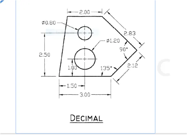
- The given geometry is created in AUTOCAD using primarily the line and circle tools.The procedure of drawing is explained in detail with diagrams of each step and the final result is given.
PROCEDURE:
Step-1:
- Open the AUTOCAD software and Click on new Drawing Sheet.
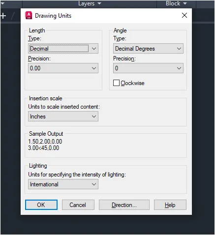
- Enter units in command box.
- Select DECIMAL in type 0.00 in Precision and meters in units to scale insted content Press OK.
Step-2:
- Turn off the ortho mode
- L for the line command .
- Set the coordinate of origin as 0,0
- Drag the mouse rightwards
- Type 3 as length of line and press enter.
- Press escape.
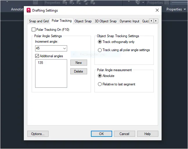
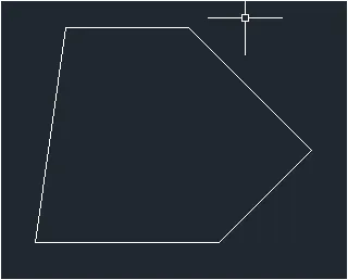
Step-3:
- Select the line tool by entering line command in the command tab.
- Select the first point as 0,0 in the command line.
- Specify the next point as @3,0 in the command line.
- Specify the ext point as @2.12<45 in the command line
- Specify the next point as @2.83< in the command line.
- Specify the next point as @ -2.00<0 in the command line.
- Click close on the command line.
Step-4:
- Select the circle tool by entering CIRCLE command in the command tab.
- Specify the center point of circle 1.50,1.00 in the command line.
- Select the diameter option in the command line.
- Specify the daimeter of circle 1.20 in the command line.
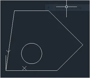
Step-5:
- Select the circle tool by entering CIRCLE command in the command tab.
- Specify the next point of circle 1.50,2.50 in the command line.
- Select the diameter option in the command line.
- Specify the diameter of circle 0.80 in the command line.
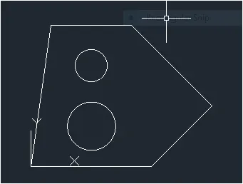
Step-6:
- Enter DIMSTYLE command in the command tab to open the dimension style manager dialog box.
- Click on the modify tab.
- Under the lines option change the color of the dimensions and extensions lines.
- Under the symbols of arrow and option change the arrow size to 0.15 .
- Under the text option change the text height to 0.15
- Click OK.Then click on the current and close the dialog box.
- Select the dimensions tool by entering DIM in the command line.
- Select the first point and second point of the object to be measured, then drag the dimension line to the desired location.Repeat for all the objects to be measured.
- For measuring angles use the DIMANGULAR command.
- Select the lines making the angles and press enter.
- Enter text command in the command line.
- Specify height of text as 0.2.
- Specify angle of rotation of text as 0.00
- Enter the name of the drawing.
- Click enter and press Esc.
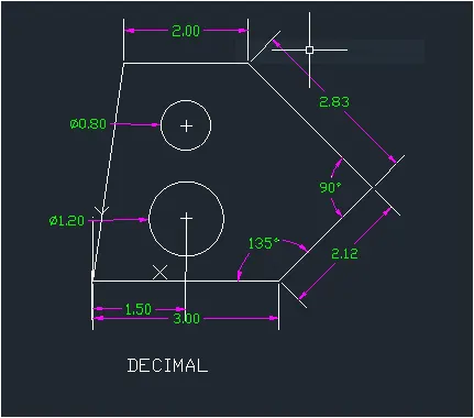
RESULT:
QUESTION 2):
AIM: DRAFT THE GIVEN GEOMETRY USING ARCHITECTURAL UNIT SYSTEM:
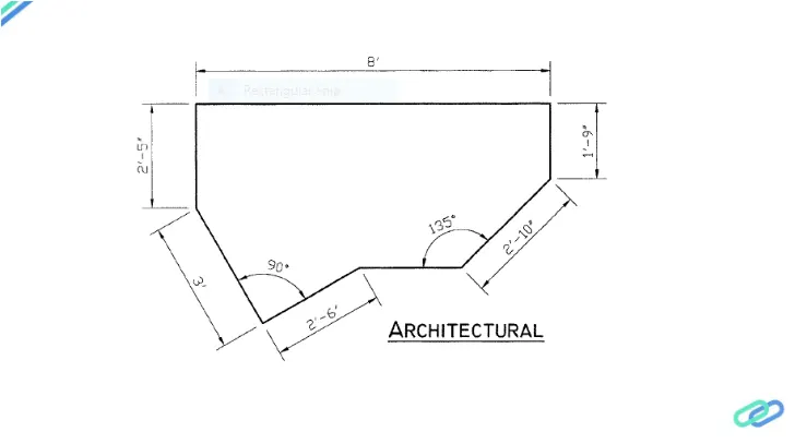
- The given geometry is created in autocad using primarily the line tool.
- The procedure of drawing is explained in detail with diagrams of each step and the final result is given.
PROCEDURE:
Step-1:
- Open the Autocad software and click on new for a new drawing sheet.
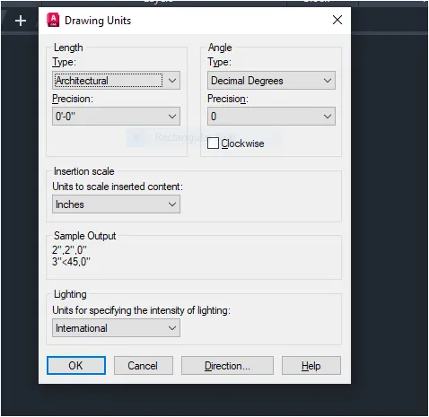
- Enter UNITS in command box
- 0'0.0" in precision and inches in Units to scale inserted press ok.
- Also select Architectural Dimension style.
Step-2:
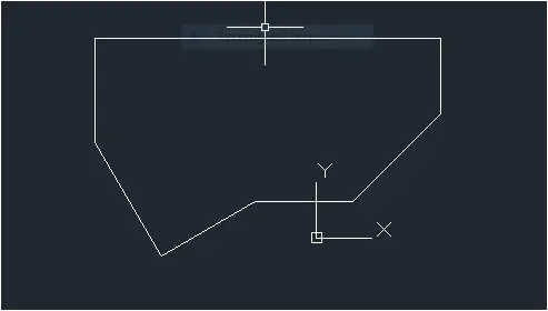
- Select the line tool by entering Line command in the command tab.
- Specify the first point as 10,10 in the command line.
- Specify the coordinate of the next point as @ 2'10" <45
- Specify the coordinate of the next point as @ 0,1'9"
- Specify the coordinate of the next point as @-8',0
- Specify the coordinate of the next point as @0,-2'5"
- Specify the coordinate of the next point as @ 3' <300
- Specify the coordinate of the next point as @ 2'6" <30
Step-3:
- Enter DIMSTYLE command in the command tab to open the diamension style manager dialog box.
- Click on the modify tab.
- Under the lines option change the color of the dimensions and extensions lines.
- Under the symbols of arrow and option change the arrow size to 0'-2^1/2"
- Under the text option change the text height to 0'-2^1/2"
- Click ok.Then click on the current and close the dialog box.
- Select the first point and second point of the object to be measured ,then drag the dimension line to the desired location.Repeat for all the objects to be measured.
- For measuring angles use the DIMANGULAR command.
- Select the lines making the angles and press Enter.
- Enter text command in the command line.
- Specify the start point as 0'3^1/2"
- Specify angle of rotation of text as 0.00
- Enter the name of the drawing.
- Click Enter and press Esc.
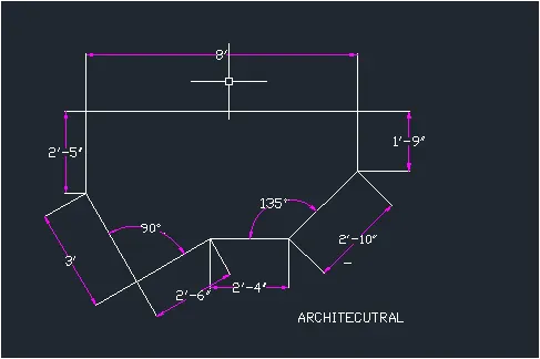
RESULT:
QUESTION 3).
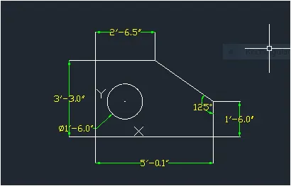
AIM: DRAFT THE GIVEN GEOMETRY USING ENGINEERING UNIT SYSTEM:
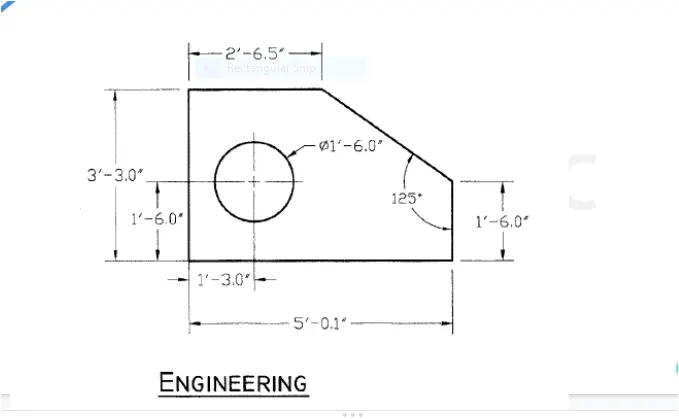
The given geometry is created in autocad using primarily the line and circle tools.The procedure of drawing is explained in detail with diagrams of steps and the final result is given
PROCEDURE:
Step-1:
- Go to start menu slect ATOCAD .
- In command line type in STARTUP enter.
- Go to application Menu and select New.
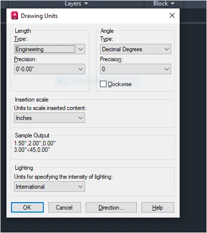
- In the create new drawing dialog box we do the advanced setup and select engineering unit of measurement and select precision as 0'-0.0"
- enter 'UNITS' command in command tab.
- In the drawing units dialog box select engineering in type 0'0.0" in precision and inches in insertion scale.
- click on -ok.
Step-2:
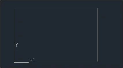
- Select the line tool by entering LINE.
- Specify the first point as the 0'0.0",0'0.0" in the command line.
- Specify the next point as the @5'0.1",0'0.0"
- Specify the next point as the @0'0.0",3'3.0"
- Specify the next point as the @-5'0.1",0'0.0" in the command line.
- Click close on the command line.
Step-3;
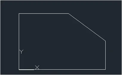
- Select the CHAMFER tool by entering CIRCLE command in the command tab.
- Select the angleoption in the command line.
- Specify the Chamfer length 1'6.0" in the command line.
- Specify the angle from the first line as 125.
- Select the first CHAMFER line.
- Select the distance option in the command line
- Specify the distance option in the command line.
- Specify the first chamfer distance as 1'9.0"
- Specify the second chamfer distance as 2'5.6'
- Then select the second line.
Step-4:
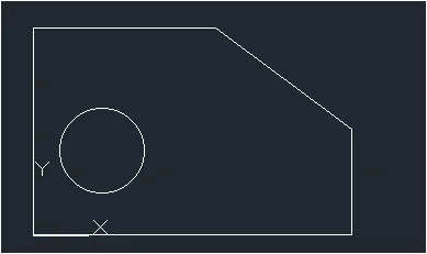
- Select the circle tool by entering CIRCLE command in the command tab.
- Specify the center point of the circle as 1'3.0",1'6.0"in the command line.
- Select the diameter option in the command line.
- Specify diameter of circle as 1'6.0
Step-5:
- Enter DIMSTYLE command in the command tab to open the dimension style manager dialog box.
- Click on the modify tab.
- Under the lines option change the color of the dimensions and extensions lines.
- Under the symbols of arrow and option change the arrow size to 0'-3.25".
- Under the text option change the text height to 0'-3.25'
- Click ok.Then click on the curent and close the dialog box.
- Select the dimension tool by entering DIM in the command line.
- Select the first point and second point of the object to be measured,then drag the dimension line to the desired location.Repeat for all the object to be measured.
- For measuring angles use the DIMANGULAR command.
- Select text command in the command line.
- Specify the start point of text as required.
- Specify height of text as 0'2.5"
- Specify angle of rotation of text as 0.00.
- Enter the name of the drawing.
- Click enter and press Esc.
RESULT:
QUESTION 4).
AIM:DRAFT THE GIVEN GEOMETRY 4 USING AUTOCAD TOOLS:
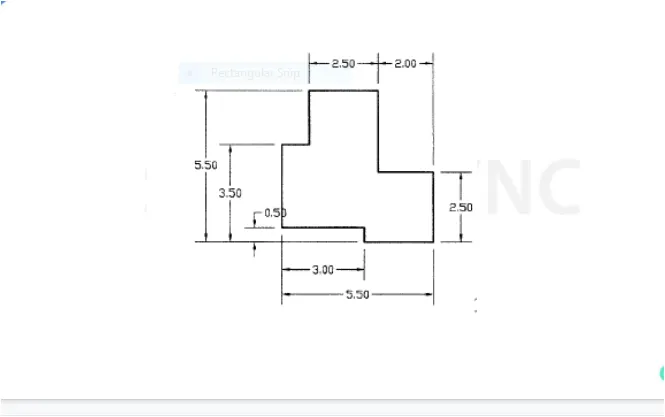
The given geometry is created in autocad using primarily the line tool.The procedure of drawing is explained in detail with diagrams of each step and the final result is given.
PROCEDURE:
Step-1:
- Go to start menu,select Autocad.
- In command line type;Startup enter.
- Enter new value of startup:1
- G o to application menu and select New.
- In create new drawing dialog box we do the advance setup and select the DECIMAL unit of measurement.
- Enter UNITS command in the command tab.
- In drawing units dialog box is there select decimal in type 0.00' in precision and meter in insertion scale Click on OK.
Step-2:
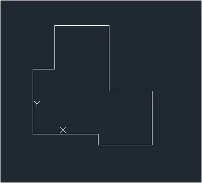
- Select the line tool by entering LINE command in the command tab.
- Specify the first point as @ 0,0 in the command line.
- Specify the next point as @ 3.00,0.00 in the command line
- Specify the next point as @0.00,-0.50 in the command line
- Specify the next point as @2.50,0.00 in the command line
- Specify the next point as @ 0.00,2.50 in the command line
- Specify the next point as @ -2.00,0.00 in the command line
- Specify the next point as @ 0.00,3.00 in the command line
- Specify the next point as @ -2.50,0.00 in the command line
- Specify the next point as @ 0.00,-2.00 in the command line
- Specify the next point as @ -1.00,0.00 in the command line
- Click close on the command line.
Step-3
- Enter DIMSTYLE command in the command tab to open the dimension style manager dialog box.
- Click on the modify tab.
- Under the lines option change the color of the dimensions and extensions lines.
- Under the symbols of arrow and option change the arrow size to 0'-3.25".
- Undr the text option change the text height to 0'-3.25''
- Click OK.Then click on the current and close the dialog box.
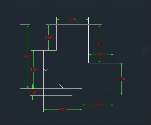
- Select the dimension tool by entering DIM in the command line.
- Select the first point and second point of the object to be measured, then drag the dimension line to the desired location. Repeat for all theobjects to be measured.
- Press Esc to cancel the dimension tool.
RESULT:
QUESTION 5.
AIM: DRAFT THE GIVEN GEOMETRY 5 USING AUTOCAD TOOLS:
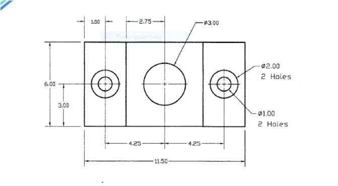
- The given geometry is created in autocad using primarily the line and circle tools.the procedure of drawing is explained in detail with diagrams of each step and the final result is given.
PROCEDURE:
Step-1:
- Open the AUTOCAD software and click on new for a new drawing sheet.
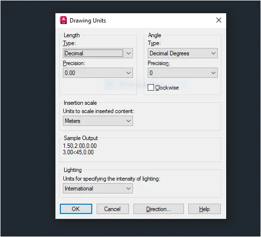
- Enter UNITS in command box.
- Select Decimal in type 0.00 in precision and meter in unit to scale inserted content press ok.
- Switch on orthomode
Step-2:
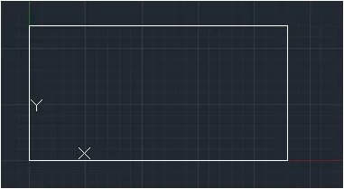
- Select the line tool by entering Line command in the command tab.
- Specify the first point as the 0,0 in the command line.
- Specify the next point as @ 11.50,0.00
- Specify the coordinate of the next point as @ 0.00,6.00
- Specify the coordinate of the next point as @ -11.50,0.00
- Click close on the command line.
Step-3:
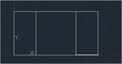
- Select the offset tool by entering OFFSET COMMAND in the command line.
- Enter 3.00 as offset distance in the command line.
- Select the leftmost vertical lineof the above drawing.
- Specify the point on the desired side to offset.
- Repeat the same for the right most vertical line of the above drawing .
- Press Esc to cancel the offset command.
Step-4:
- Select the circle tool by entering CIRCLE command in the command tab.
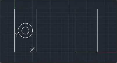
- Specify the center point of the circle as 1.50,3.00 in the command line.
- Select the diameter of the circle as 2.00
- Select the offset tool by entering OFFSET command in the command tab.
- Enter 0.50 as offset distance in the command line.
- Select the left circle.
- Click on the inside of the circle.
- Press Esc to cancel the offset command.
Step-5:
- Select the circle tool by entering CIRCLE command in the command tab.
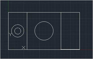
- Specify the center point of the circle as 5.75,3.00 in the command line.
- Select the diameter option in the command line.
- Specify diameter of circle as 3.00
Step-6:
- Select the circle tool by entering CIRCLE command in the command tab.
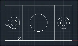
- Specify the center point of the circle as 10.03,3.00 in the command line.
- Select the diameter of the circle as 2.00
- Select the offset tool by entering OFFSET command in the command tab.
- Enter 0.59 as offset distance in the command line.
- Select the left circle.
- Click on the inside of the circle.
- Press Esc to cancel the offset command.
Step-7:
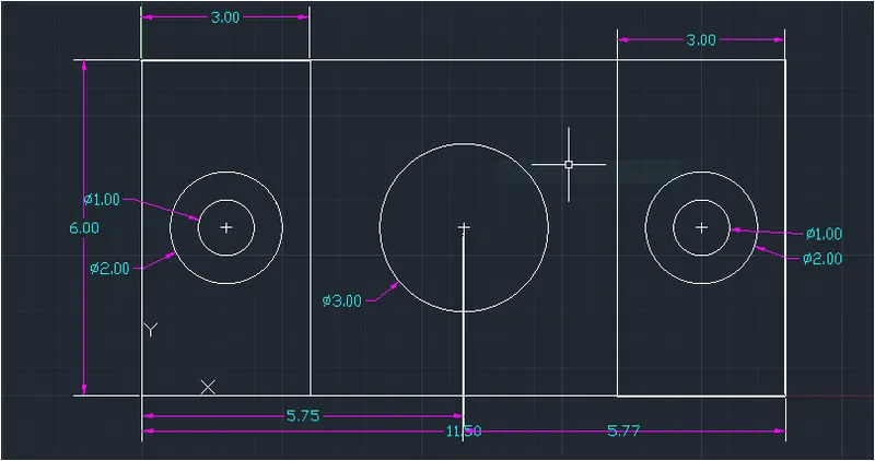
- Enter DIMSTYLE command in the command tab to open the dimension style manager dialog box.
- Click on the modify tab.
- Under the lines option change the color of the dimensions and extensions lines.
- Under the symbols of arrow and option change the arrow size to 0.25 .
- Under the text option change the text height to 0.25
- Click OK. Then click on the current and close the dialog box.
- Select the first point and second point of the object to be measured, then drag the dimension line to the desired location.Repeat for all the objects to be measured.
- ENTER text command in the command line.
- Specify the start point of text as required.
- Click enter and press Esc.
RESULT:
QUESTION 6).
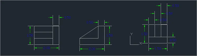
AIM: DRAFT THE GIVEN GEOMETRY 6 USING AUTOCAD TOOLS.
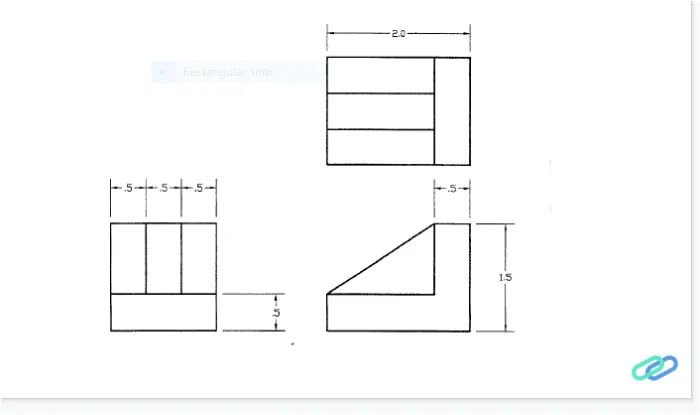
- The given geometry is created in autocad using primarily the line tool.The procedure of drawing is explained in detail with a diagram of each step and the final result is given.
PROCEDURE:
Step-1:
- Open AUTOCAD software and click start drawing tab.
- Enter UNITS in command box.
- Select DECIMAL in type 0.0 in precision and meter in units press ok.
- Switch on orthomode.
- Enter L in commanf line.
Step-2:
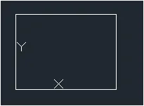
- Select the line tool by entering LINE command in the command tab.
- Specify the first point as 4.5,2.5 in the command line.
- Specify the coordinate of the next point as @2.0,0.0 in the command line.
- Specify the coordinate of the next point as @ 0.0,1.5 in the command line.
- Specify the coordinate of the next point as @ -2.0,0.0 in the command tab.
- Enter 0.5 as offset distance in the command line.
- Select the right most vertical line of the drawing.
- Specify the point on the desired side to offset.
- Repeat the same for the upper horizontal line of the drawing.
- Press Esc to cancel the offset command.
- Select the trim tool by entering TR command in the command tab.
- Press ENTER.
- Press Esc to cancel the trim command.
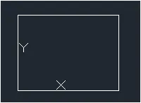
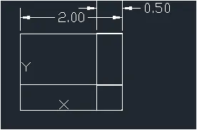
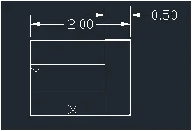
Step-3:
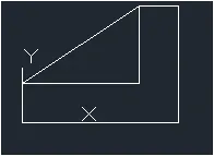
- Select the line tool by entering LINE command in the command tab.
- Specify the first point as 4.5,0.0 in the command line.
- Specify the coordinate of the next point as @ 2.0,0.0 in the command line.
- Specify the coordinate of the next point as @ -0.5,0.0 in the command line.
- Specify the coordinate of the next point as @-1.5,-1.0 in the command line.
- Click close on the command line.
- Select the first point as 4.5,0.5 in the command line.
- Specify the coordinate of the next point as @ 1.5,0.0 in the command line.
- Specify the coordinate of the next point as @ 0.0,1.0 in the command line.
- Press Esc to cancel the line tool.
Step-4:
- Select the line tol by entering line command in the command tab.
- Specify the first point as 0.0,0.0 in the command line.
- Specify the coordinate of the next point as @ 1.5,0.0 in the command line.
- Specify the coordinate of the next point as @ 0.0,1.5 in the command line.
- Specify the coordinate of the next point as @ -1.5,0.0 in the command line.
- Click close on the command line.
- Select the offset tool by entering OFFSET command in the command tab.
- Enter 0.5 as offset distance in the command line .
- Select the point on the desired side to offset.
- Repeat the same for the upper horizontal line of the drawing.
- Press Esc to cancel the offset command.
- Select the trim tool by entering TR command in the command tab.
- Press Enter.
- Press Esc to cancel the trim command.
Step-5:
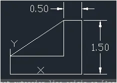
- Enter DIMSTYLE command in the command tab to open the dimension style manager dialog box.
- Click on the modify tab.
- Under the lines option change the color of the dimensions and extensions lines.
- Under the lines option change the color of the dimensions and extensions lines.
- Under the symbols of arrow and option change the arrow size to 0.1 .
- Under the text option change the text height to 0.1
- Click ok.Then click on the current and close the dialog box.
- Select the dimensions tool by entering DIM i the command line.
- Select the first point and second point of the object to be measured,then drag the dimension line to the desired location.Repeat for all the object to be measured.
- Press Esc to cancel the dimension tool.
RESULT:
QUESTION -7.
AIM: DRAFT THE GIVEN GEOMETRY 7 USING AUTOCAD TOOLS:
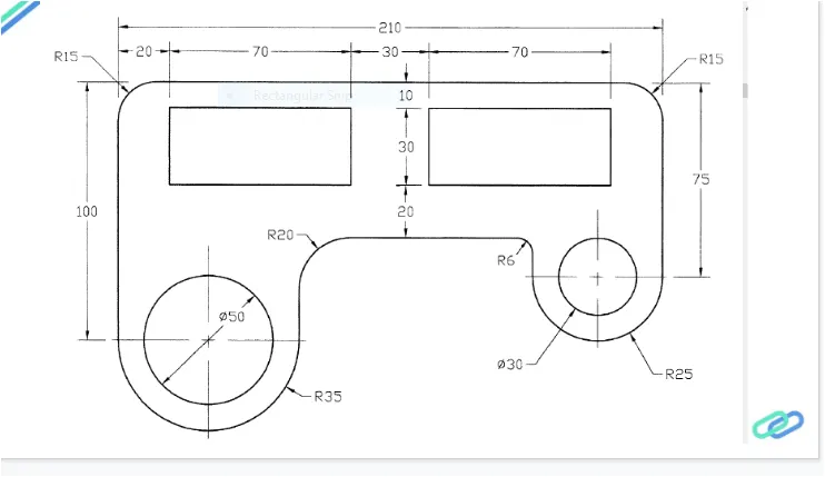
- The given geometry is created in autocad using primarily the line and circle tools.The procedure of drawing is explained in detail with a diagram of each step and the final results is given
PROCEDURE:
Step-1:
- Open the AUTOCAD software and click start drawing tab.
- Enter units in command box.
- Select DECIMAL in type 0.00 in precision and meter in units press OK
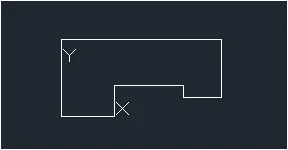
Step-2:
- Switch on orthomode.
- Enter L in command box.
- Enter 0,0 as first point
- Enter @70,0 as next point.
- Enter @ 0,40 as next point.
- Enter @ 90,0 as next point
- Enter @ 0,-15 as next point.
- Enter @ 50,0 as next point.
- Enter @ 0,75 as next point.
- Enter @ -210,0 as next point
- Enter @ 0,-100 as next point.
- Press enter or close.
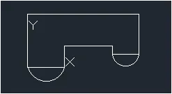
Step-3:
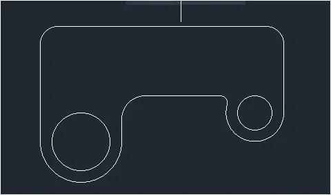
- Click arc tool in ribbon.
- Click start End Redius from the dropdown.
- Click start and end point .
- Enter 35 as radius.
- Click arc tool in ribbon.
- Click start end radius from the dropdown.
- Enter 25 as radius.
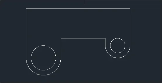
Step-4:
- Click circle Diameter in ribbon.
- Enter 35,o as center.
- Enter 50 as diameter.
- Click circle Diameter in ribbon.
- Enter 185,25 as center .
- Enter 30 as diameter
- Delet two unconnected lines.
Step-5:
- Enter f and select radius .
- Enter 20 as fillet radius.
- Select 1st object and 2nd object
- Enter F and select radius.
- Enter 6 as Fillet radius.
- Select 1st object and second object
- Enter f and select radius
- Enter 15 as fillet radius.
- Select 1st object and 2nd object.
Step-6:
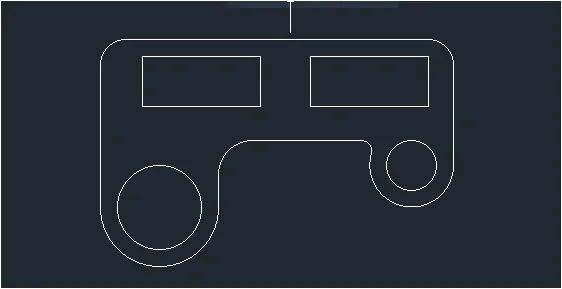
- Enter RECTANG in command tab.
- Enter 20,90 as firstcorner point
- Click Dimension
- Enter 70 as length and 30 as width.
- Enter 90,60 as another corner point
- Enter RECTANG in command tab.
- Enter 120,90 as first corner point
- Click dimension.
- Enter 70 as length and 30 as width.
Step-7:
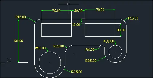
- Enter DIMSTYLE command in the command tab to open the dimension style manager dialog box.
- Click on the modify tab.
- Under the lines option change the color of the dimensions and extensions lines.
- Under the text option change the text height to 4
- Under the symbols of arrow and option change the arrow size to 4
- Click ok. Then click on the current and close the dialog box.
- Select the dimensions tool by entering DIM in the command line.
- Select the first point and escond point of the object to be measured then drag the dimension line to the desired location .Repeat for all the objects to be measuredd.
- Press Esc to cancel the dimension tool.
RESULT:
QUESTION 8).
AIM: DRAFT THE GIVEN GEOMETRY 8 USING AUTOCAD TOOLS.
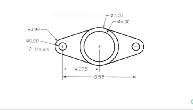
- The given geometry is created in autocad using primarily the line and circle tools. the procedure of drawing is explained in detail with a diagram of each step and the final results is given.
PROCEDURE:
Step-1:
- Open the AUTOCAD software and click start drawing tab.
- Enter units in command box.
- Select DECIMAL in type 0.00 in precision and meter in units press ok.
Step-2:
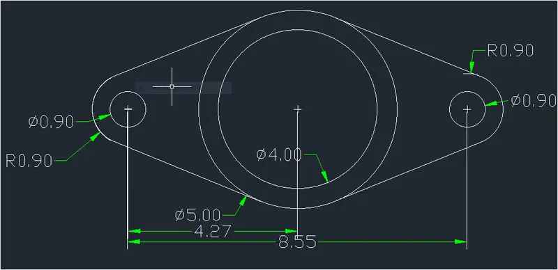
- Select the line tool by entering LINE command in command tab.
- Specify the first point as 5,5 in command line.
- Specify the coordinate next point as @8.55,0 in command line.
- Press Esc.
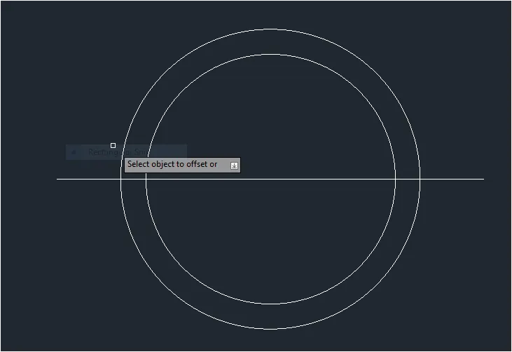
- Select circle tool by entering Circle command line in command tab.
- SPecify the center point o circle as mid point of line drawn previously .
- Select the diameter option in command line.
- Select the diameter of circle as 5
- Select the offset tool by entering offset command in the command tab.
- Enter 0.5 as offset distance in command line.
- Select the circle of diameter 5 unit .
- Click on inside of the circle.
- Press Esc.
Step-3:
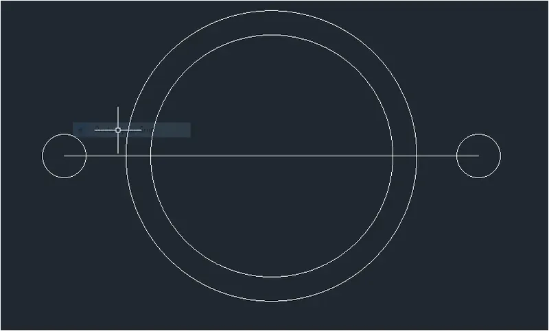
- Select the circle tool by entering CIRCLE command in command tab.
- Specify the center point of circle as the start point of the line length 8.55 unit created in above drawing.
- Select the diameter option in command line.
- Specify diameter option in command line.
- Select the circle tool again by entering CIRCLE command in command tab.
- Specify the center point of circle as the end point of the line of length 8.55 units created in the previous step.
- Select the diameter option in command line.
- Specify diameter of circleas 0.90.
Step-4:
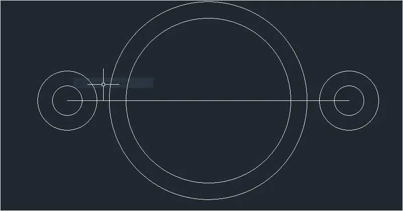
- Select the circle tool by entering CIRCLE command in command tab.
- Specify the centre point of circle as the start point of the start point of the line of length 8.55 units created in step 2.
- Specify radius of circle as 0.90
- Select the circle tool again by entering CIRCLE command in command tab.
- Specify the center point of circle as the end point of the line of length 8.55 units Created in step 2
- Specify radius of circle as 0.90
Step-5:
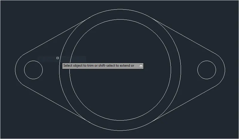
- Enter OSNAP in command line.
- In the drafting setting dialog box, under object snap option ,deselect all the snap modes and turn on only the tangent mode.
- Select the line tool by entering LINE command in command tab.
- Draw a line joining the tangent point of te circle of radius 0.90 on the right side and the circle of diameter 5
- Press Esc to cancel the line tool
- Repeat the above procedure to draw all four tangents.
- Press Esc to cancel the line tool.
- Select the tri tool by entering TR command in command tab.
- Press Enter.
- Select Edge option and click on no extend.
- Select the unwanted lines to be trimed.
- Press Esc.
Step-6:
- Enter DIMS in command box.
- Click modify.
- Click Symbols and arrow enter required size.
- Click Text Height.
- Click ok
- Select standard in style,click Set Current .Click close.
RESULT:
QUESTION 9:
AIM: DRAFT THE GIVEN GEOMETRY 9 USING AUTOCAD TOOLS:
- The given geometry is created in autocad using primarily the line and circle tools.The procedure of drawing is explained in detail with a diagram of each step and the final result is given.
PROCEDURE:
Step-1:
- Go to start enu select AUTOCAD.
- In the command line type in startup enter.
- Enter new value of startup 1
- Go to application menu and select new.
- In the create New Drawing dialog box we do the advanced setup and select the engineering unit of measurement and select precision as 0'-0.0"
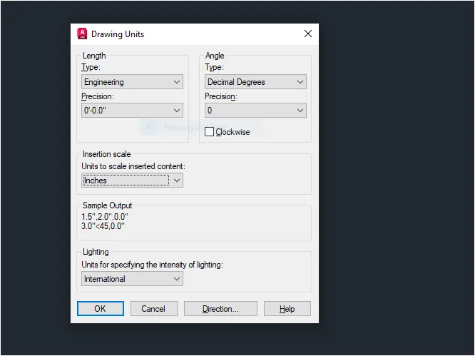
- Enter UNITS command in command tab.
- In the drawing units dialog box select Engineering in type 0-0.0' in precision and inches in insertion scale
- Click on OK
Step-2:
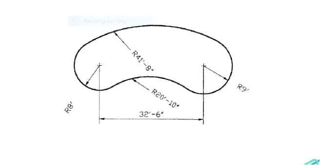
- Select the line tool by entering LINE command in the command tab.
- Specify the first point as 10,10 in the commend line.
- Specify the coordinate of the next point as @ 32'6",0'0.0"
- Press Esc to cancel the line tool.
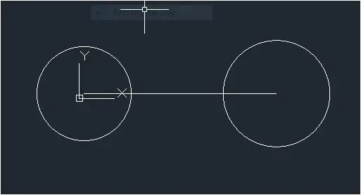
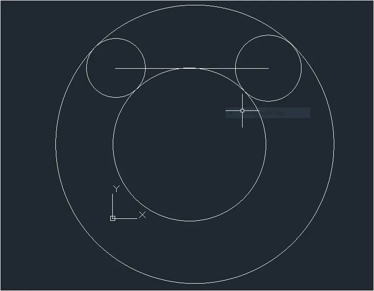
- Select the circle tool by entering Circle command in the command tab.
- Specify the center point of the circle as the start point of the line of length 32'6" units created before.
- Specify radius of circle as 8
- Select the circle tool by entering circle command in the command tab.
- Specify the center point of the circle as the start point of the line of length 32'6'' units created before.
- Specify radius of circle as 9'.
Step-3:
- Select the circle tool by entering CIRCLE command in the command tab.
- Specify the tan tan radius option in the command line.
- Select the first tangent by clicking on the top tangent of the right circle.
- Specify radius as 41'8"
- Again select the circle tool by entering CIRCLE command in the command tab.
- Specify the tan tan radius option in the command line.
- Select the first tangent by clicking on the bottom tangent of the left circle.
- Select the second tangent by clicking on the bottom tangent of the right circle.
- Specify radius as 20'10".
Step-4:
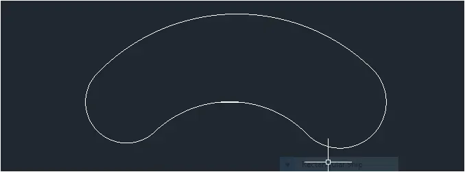
- Select the trim tool by entering tr command in the command tab.
- Erase the unwanted things on the drawing.
Step-5:
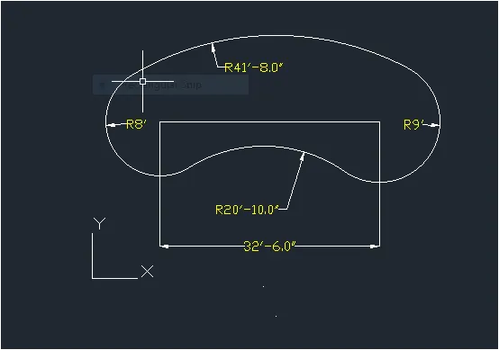
- Enter DIMSTYLE command in the command tab to open the dimension style manager dialog box.
- Click on the modify tab.
- Under the symbols of arrow and option size to 15"
- under the text option change the text height to 15"
- Click ok. then click on the current and close the dialog box .
- Select the dimension tool by entering DIM in the command line.
- Select the first point and second point of the object to be measured, then drag the dimension line to the desired location.Repeat for all the objects to be measured.
- Press Esc to cancel the dimension tool.
RESULT:
QUESTION -10.
AIM: DRAFT THE GIVEN GEOMETRY 10 USING AUTOCAD TOOLS:
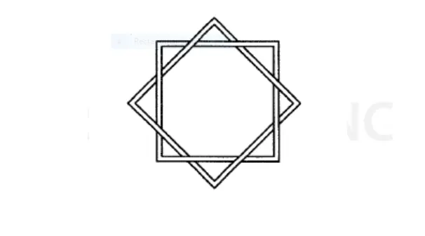
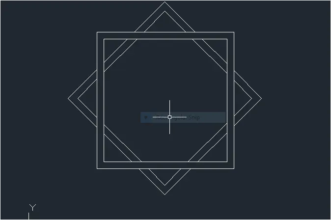
- The given geometry is created in autocad using primarily the rectangle tools.the procedure of drawings is explained in detail with a diagram of each step and the final result is given.
PROCEDURE:
Step-1:
- Open the AUTOCAD software and click start drawing tab.
- Enter units in command box
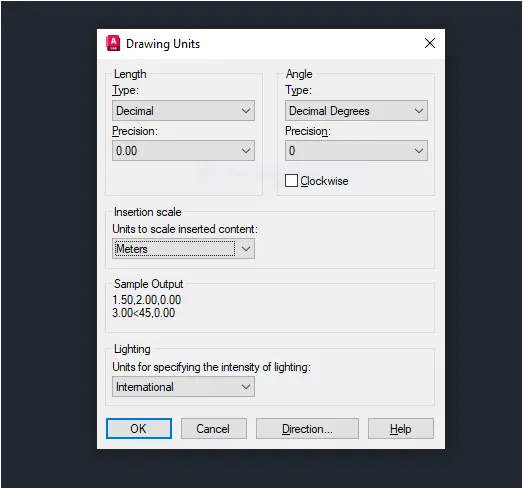
- Select DECIMAL in type 0.00 in precision and meter in units press ok.
Step-2:
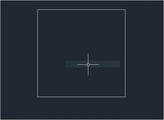
- Select the rectangle tool by entering Rec command in the command tab.
- Specify the first point as 5,5 in command line.
- Select dimension option in the command line.
- Specify the length of rectangle as 10,in command line.
- Specify width of rectangle as 10 in the command line.
- Move the cursor towards the upward and click enter.
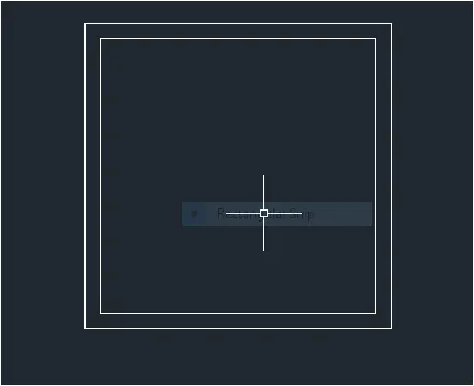
- Select the offset tool by entering offset command in the command line.
- Enter 0.5 as offset distance in the command line.
- Select the rectangle of size 10*10
- Click on the inside of the rectangle
- Press Esc.
Step-3:
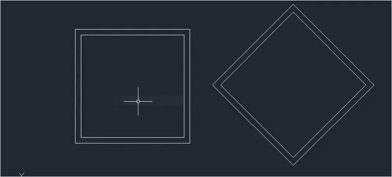
- Select the copy tool by entering copy command in the command tab.
- Select the drawing created in step 2
- Specify the base point and click entr.
- Select the rotate tool by entering RO command in the command tab.
- Select the copied object and specify the base point
- Specify the rotation angle as 45
- Select the move tool by entering M command in the command tab.
- Select the rotated object and specify the base point
- Move the object to the desired location (keep ortho mode 0ff)
- Select the trim tool by entering Tr command in the command tab.
- Press enter.
- Select unwanted lines to be trimed
- Press Esc.
RESULT:
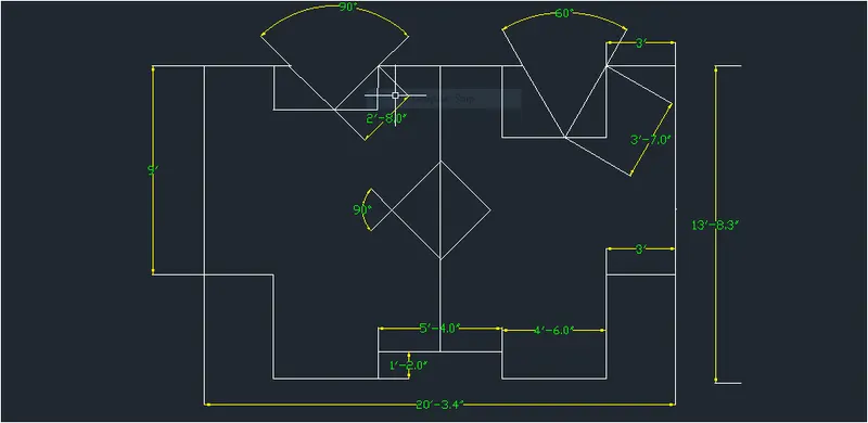
QUESTION-11:
AIM: DRAFT THE GIVEN GEOMETRY 11 USING AUTOCAD TOOLS:
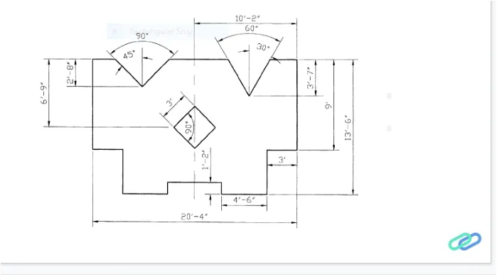
- The given geometry is created in autocad using primarily the line tool. the procedure of drawing is explained in detail with a diagramof each step and the final result is given.
PROCEDURE:
Step-1:
- Go to start Menu Select Autocad
- In the command line type in startup.
- Enter new value of startup 1
- Go to application menu and select new.
- In the create New drawing dialof box we do the advanced setup and select the engineering unit of measurement and select precision as 0'-0.0"
- Enter UNITS command in the command tab.
- In the drawing units dialog box select Engineering in type 0'-0.0" in precision and inchesin insertion scale
- Click on ok.
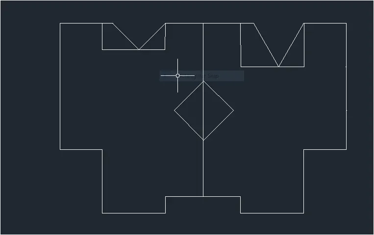
Step-2:
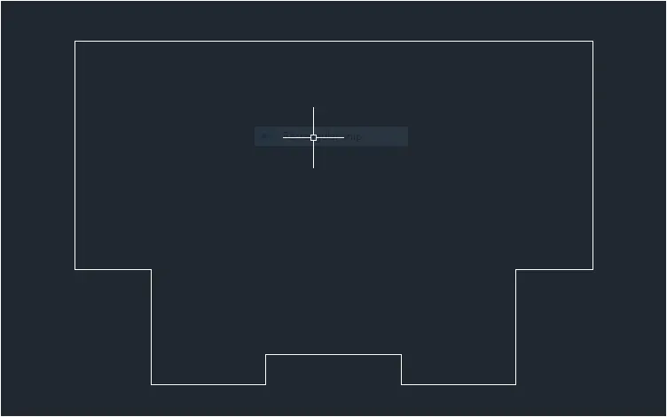
- Select the line tool by entering LINE command in the command tab.
- Keep ortho mode on.
- Specify the first point as 0,0 in the command line.
- Specify the coordinate of the next point as @-3',0' in the command line.
- Specify the coordinate of the next point as @0',-9 in command line.
- Specify the coordinate of the next point as @ 3',0' in the coomand line.
- Specify the coordinate of the next point as @ 0',-4'6" in the command line.
- Specify thecoordinate the next point as @ 4'6",0' in command line.
- Specify the coordinate of the next point as @ 0',1'2'' in the command line.
- Specify the coordinate of the next point as @ 5'4",0' in the command line.
- Specify the coordinate of the next point as @ 0',-1'2" in the command line.
- Specify the coordinate of the next point as @ 4'6'',0' in the command line.
- Specify the coordinate of the next point as @ 0',4'6" in the command line.
- Specify the coordinate of the next point as @ 3',0 in the command line.
- Specify the coordinate of the next point as @0',9' in the command line.
- Specify the coordinate of the next point as @ -3',0' in the command line.
- Press Esc to cancel the line tool.
Step-3:
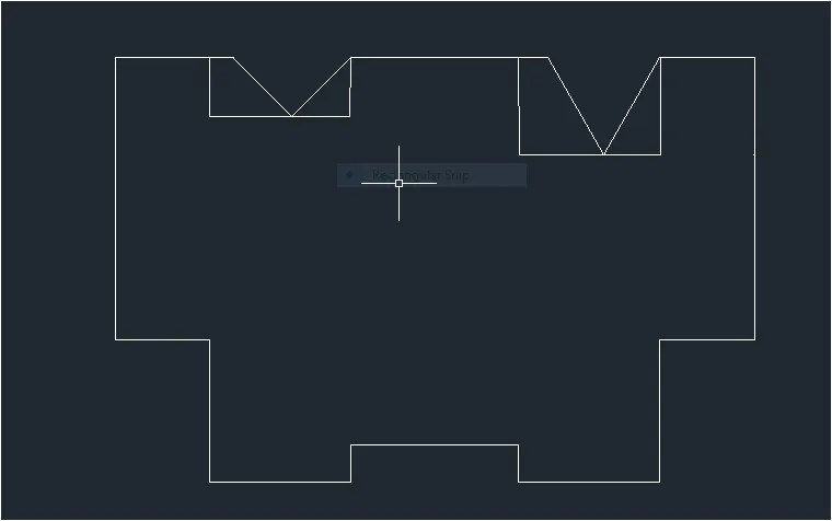
- Turn ortho off and click on polar tarcking from the status bar and select 30,60,90... from the drop down list.
- Select the line tool by entering LINE command in command tab.
- Specify the first poit at b then pointing the cursor downward enter a length of 3'7"
- Next pointing the cursor towards left draw a line of any arbitary length of over 2
- press Esc.
- Select the mirror tool by enetring MIRROR Command in the command tab.
- Select the objects to mirror and click enter.
- Select first point mirror line.
- Select second point of mirror line.
- Click No in earse source object 1? prompt.
- Again click on the polar tracking from the status bar and select 45,90,135... from the dropdown list.
- Select the line tool by entering LINE command in command tab.
- Specify the first point at a then pointing the cursor downward enter a length of 2'8",
- Next pointing the cursor towards left draw a line of any arbitary length of over 3'
- Press Esc.
- Select the mirror tool by entering MIRROR command in command tab.
- Select first point of mirror line.
- Select second point of mirror line.
- Click no in erase source object? prompt
- SElect the line tool and join the two open ends of the drawing.
- Press Esc to cancel.
- Again select the line tool and draw bisecting both the angles
- Press Esc.
Step-4:
- Trim nad erase the unwanted lines in the drawing.
- Select the line tool and draw a line from the midpoint of base line such as that it divides the geometry into two halves.
- Press Esc.
- Select the rec tool by entering commnad in command tab.
- Specify the first point as 7'2', in the command line.
- Select dimensions option in the command line.
- Specify length and width of rectangle as 3' in command line.
- Move the cursor towards the upward and click enter.
- Select the rotate tool by entering RO command in command tab.
- Select the rec of size 3',3' and specify the base point at the bottom left corner of the rectangle.
- Using polar tracking rotate the rectangle to an angle about 45 the middle line.
Step-5:
- Enter DIMSTYLE command in the command tab to open the dimension style manager dialog box.
- Click on the modify tab.
- Under the line option change the color of the dimensions and extension lines.
- Under the symbols of arrow and option change the arrow size to 0.5"
- Under the text option change the text height to 0.5"
- Click ok the, click on the current and close dialog box.
- Select the first point and second point of the object to be measured then drag the dimension line to the desired location.Repeat for all the object to be measured.
- Press Esc to cancel the dimension tool.
- For angle measurement select the dimangular tool by entering.
- Dimangualr in the command line and then specify the angles of measurement.
RESULT: