Creation of geometries by Coordinate system methods using AutoCad
Q1.Create the geometries from P1 to P2 using all the coordinates system methods. You need to use the Line tool to create the geometries. Where required you need to use the circle tool.
Please read the drawings and find out the missing dimensions before working on the sketches.
Note: Use the Imperial Template and the Decimal Units to draft the features. Dimensions are there for references.
Ans:
Aim:
(A) To create the geometries from P1 toP2 using all the coordinates system methods and P3 toP10 by any one coordinate system.
(B) To draw the profile and the trusses using any coordinate system methods.The dimensions are there for reference.
Introduction:
- Before going to the drawing ,we should know about the coordinates systems.
- In Autocad ,there are two coordinate system, i.e cartesian and polar .To these coordinate system,the absolute and relative coordinates of Autocad are applicable.
Coordinate system:
- Coordinate system is a system whenre numbers are used to determine the unqiue position of points and/or other geometric elements.
- Also coordinates in Autocad can be set by mouse,input (setting) the values of coordinates in the command line and enter coordinates using dynamic input.
1.Absolute coordinate systems.
2. Relative coordinates Sytems.
a)Relative rectangular coordinates.
b) Relative polar coordinates.
3. Direct distance entry.
1.Absolute coordinate system:
- In this system,all points are established at some distance in the X and Y axis (sometimes Z-axis) from a coomon origin(usually0,0).
2.Relative coordinate system:
- The location of a relative coordinate is defined by its distance from a reference point .
- In Autocad ,when using this system the first point of the drawing /geometry is always absolute,i.e. it is established with respect to origin (0,0) and then all the successive positions are established with respect to their preceding point .
- This system is further classified as.
a) Relative rectangular coordinates:
- It is a coordinate system that specifies each point by a pair of numerical coordinates inthe X- axis and Y-axis .
- In this sytem ,the points succeeding the first point are typed in as '@X,Y' in the command line.
b)Relative polar coordinates:
- This system specifies the distance (length)and angle of a particular point with respect to its previous point.
- In the Relative polar coordinates system,points are established by typing @ distance.
3.Direct distance entry method:
- It is another popular method used for drawing different shapes/geometries in Autocad.
- The direct distance entry method snables the user to draw an object by simply pointing the cursor in the desired direction and entering the required distance in the command line.
Commands used:
- Line command.
- Dimlinear command.
- Text command.
- Circle command.
Procedure:
- Starting AutoCAD Software:
- Go to Start Menu,select AutoCAD 2022.
- Click on START DRAWING.
- In the Command line type in : STARTUP (ENTER).
- Enrer new value of startup:1
- Go to application Menu and select New.
- In the 'Create New Drawing' dialog box,select the 'Imperial System in the start from Scratch 'option.
- Next select the 'Decimal using system from the 'Advanced Setup' option.
- Set the limits by entering LIMITS in the Command tab.The lower-left corner is specified as0,0 and the upper-right corner is specified as 100,100.
- [Note: The above procedure is followed each time a new drawing is to be created.]
(A).To calculate the geometries fromP1 to P2 using all the coordinates system methods:
I.Drafting the geometry for P1 by using all coordinates System Methods:
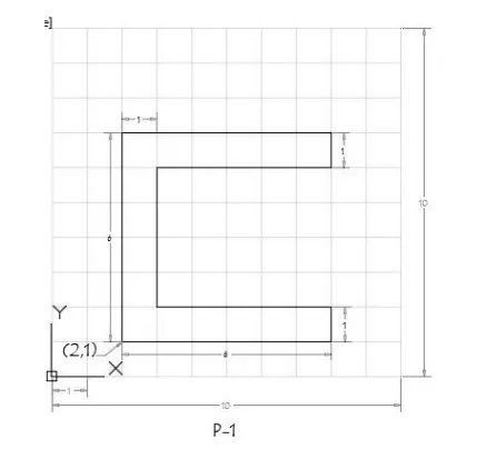
a) Absolute coordinates system:
Steps:
- Select the line tool from the ribbon tab or by entering the 'Line' command in the command tab.
- Specity the starting coordinate of point 1 as 2,1.
- Specify the next coordinate of point2 as8,1.
- Specify the next coordinate of point 3 as 8,2.
- Specify the next coordinate point 4 as3,2
- Specify the next coordinate point 5 as3,6.
- Specify the next coordinate point 6 as 8,6.
- Specify the next coordinate point 7 as 8,7.
- Specify the next coordinate point 8 as 2,7.
- Then for the last point ,click 'Close'on the command line.
Result:
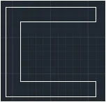
b)Relative Rectangular coordinate System;
Steps:
- Select the line tool from the ribbon tab or by entering the 'Line' command in the command tab.
- Specify the starting coordinate of point 1 as2,1.
- Specify the next coordinate of point 2 as @6,0
- Specify the next coordinate of point 3 as @0,1
- Specify the next coordinate of point 4 as @-5,0
- Specify the next coordinate of point 5 as @0,4
- Specify the next coordinate of point 6 as @5,0
- Specify the next coordinate of point 7 as @0,1
- Specify the next coordinate of point 8 as @ -6,o
- Then for the last point ,Click 'Close' on the command line.
Result:
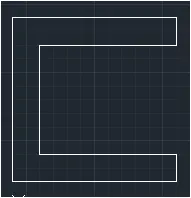
c)Relative Polar Coordinate system:
Steps:
- Select the line tool from the ribbon tab or by entering the 'Line' command in the command tab.
- Specify the starting coordinate of point1 as 2,1.
- Specify the next coordinate of ponit 2 as @6<0,
- Specify the next coordinate of point 3 as @1<90
- Specify the next coordinate of point 4 as @ 5<180
- Specify the next coordinate of point 5 as @ 4 <90
- Specify the next coordinate of point 6 as @ 5< 0
- Specify the next coordinate of point 7 as @ 1< 90
- Specify the next coordinate of point 8 as @ 6 < 180
- Then for the last point ,click 'Close' on the coomand line.
Result:
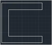
d)Direct Distance Entry method:
Steps:
- Select the Line too; from the ribbon tab or by entering the' Line ' command in the command tab.
- Specify the starting coordinate of point 1 as 2,1
- Enter the length of point 2 as 6 in the command line towards the +ve x-axis.
- Enter the length of point 3 as 1 in the command line towards the +ve y-axis.
- Enter the length of point 4 as 5 in the command line towards the -ve x-axis
- Enter the length of point 5 as 4 in the command line towards the +ve y-axis
- Enter the length of point 6 as 5 in the command line towards the +ve x-axis
- Enter the length of point 7 as 1 in the command line towards the +ve y-axis.
- Enter the length of point 8 as 6 in the command line towards the -ve x-axis.
- Then for the last point ,Click 'Close' on the command line.
Result:
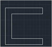
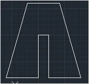
II.Drafting the geometry for P2 by using all coordinates system methods:
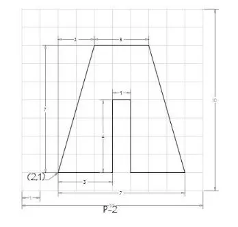
a)Absolute Coordinate System:
Steps:
- Select the line tool from the ribbon tab or entering the 'Line'command in the command tab.
- Specify the starting coordinate of point 1 as 2,1
- Specify the next coordinate of point 2 as 5,1
- Specify the next coordinate of point 3 as 5,5
- Specify the next coordinate of point 4 as 6,5
- Specify the next coordinate of point 5 as 6,1
- Specify the next coordinate of point 6 as 9,1
- Specify the next coordinate of point 7 as 7,8
- Specify the next coordinate of point 8 as 4,8
- Then for the last point click 'Close' on the command line.
Result:
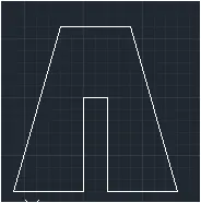
b) Relative Rectangular Coordinate System:
Steps:
- Select the line tool from the ribbon tab or entering the 'Line' command in the command tab.
- Specify the starting coordinate of point 1 as2,1
- Specify the next coordinate of point 1 as @ 3,0
- Specify the next coordinate of point 3 as @0,4
- Specify the next coordinate of point 4 as @1,0
- Specify the next coordinate of point 5 as @0,-4
- Specify the next coordinate of point 6 as @3,0
- Specify the next coordinate of point 7 as @ -2,7
- Specify the next coordinate of point 8 as @ -3,0
- Then for the last point Click 'Close' on the command line.
Result
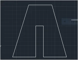
c) Relative Polar Coordinate System:
Steps:
- Select the line tool from the ribbon or by entering the 'Line' command in the command tab.
- Specify the starting coordinate of point 2 as 2,1
- Specify the next coordinate of point 2 as @3 ,0
- Specify the next coordinate of point 3 as @4<90
- Specify the next coordinate of point 4 as @ 1<90
- Specify the next coordinate of point 5 as @ 4<270
- Specify the next coordinate of point 6 as @3<0
- Specify the next coordinate of point 7 as@ 7<180
- Specify the next coordinate of point 8 as@ 3<180
- Then for the last point click 'Close' on the command line.
Result:
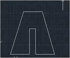
d)Direct Distance Entry Method:
Steps:
- Select the line tool from thr ribbon or by entering the 'LINE' command in the command tab.
- Specify the starting coordinate of point 1 as 2,1 in the command line.
- Enter the length of point 2 as 3 in the command line towards the +ve x-axis.
- Enter the length of point 3 as 4 in the command line towards the +ve y-axis.
- Enter the length of point 4 as 1 in the command line towards the -ve x-axis.
- Enter the length of point 5 as 4 in the command line towards the +ve y-axis.
- Enter the length of point 6 as 5 in the command line towrds the +ve x-axis.
- Enter the length of point 7 as 6 in the command line at angle of <106 from the +ve x-axis while keeping polar tracking on.
- Enter the length of point 8 as 3 in the command line towrds the -ve x-axis.
- Then for the last point ,Click'Close' on the command line .
Result:
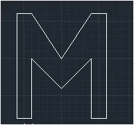
III. Drafting the geometry for P4 by using Absolute Coordinate system:
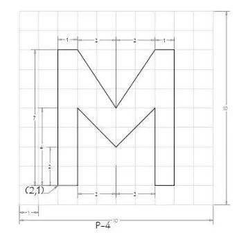
Steps:
- Select the line tool from the ribbon or by entering the line command in the command tab.
- Specify the strating coordinate of point 1 as 2,1
- Specify the next coordinate of point 2 as 3,1
- Specify the next coordinatw of point 3 as 3,5
- Specify the next coordinate of point 4 as 5,3
- Specify the next coordinate of point 5 as 7,5
- Specifty the next coordinate of point 6 as 7,1
- Specify the next coordinate of point 7 as 8,1
- Specify the next coordinate of point 8 as 8,8
- Specify the next coordinate of point 9 as 7,8
- Specify the next coordinate of point 10 as 5,5
- Specify the next coordinate of point 11 as 3,8
- Specify the next coordinate of point 12 as 2,8
- Then for the last point click'Close' on the command line.
Result:
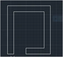
IV.Drafting the geometry for P5 by using Relative Rectangular Coordinate system:
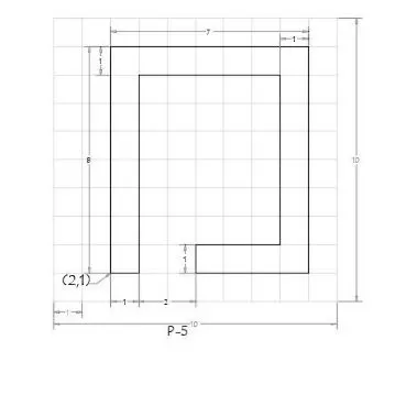
Steps:
- Select the line tool from the ribbon or by entering the 'Line' command in the command tab.
- Specify the starting coordinate of point 1 as2,1
- Specify the next coordinate of point 2 as @1,0
- Specify the next coordinate of point 3 as @0,7
- Specify the next coordinate of point 4 as @5,0
- Specify the next coordinate of point 5 as @0,-6
- Specify the next coordinate of point 6 as @-3,0
- Specify the next coordinate of point 7 as @0,-1
- Specify the next coordinate of point 8 as @4,0
- Specify the next coordinate of point 8 as @0,8
- Specify the next coordinate of point 10 as @-7,0
- Then for the last point ,Click'Close' on the Command line.
Result:
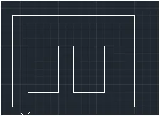
V. Drafting the geometry for P7 by using Absolute Coordinate system:
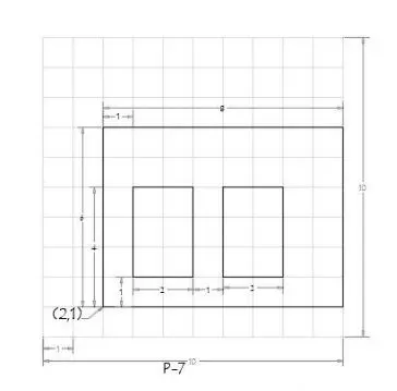
Steps:
- Select the line tool from the ribbon or by entering the 'Line' command in the line command tab.
- Specify the starting coordinate of point 1 as2,1
- Specify the next coordinate of point 2 as 10,1
- Specify the next coordinate of point 3 as 10,7
- Specify the next coordinate of point 4 as 2,7
- Click 'Close'on the command line.
- Select the line tool from the ribbon or by entering the 'Line' command in the command tab
- Specify the next coordinate of point 5 as 3,2
- Specify the next coordinate of point 6 as 5,2
- Specify the next coordinate of point 7 as 5,5
- Specify the next coordinate of point 8 as 3,5
- Click'Close' on the command line.
- Select the line tool from the ribbon or by entering the 'line'command in the command tab.
- Specify the next coordinate of point 9 as 6,2
- Specify the next coordinate of point 10 as 8,2
- Specify the next coordinate of point 11 as 8,5
- Specify the next coordinate of point 12 as 6,5
- Then for the last point Click'Close' on the command Line.
Result:
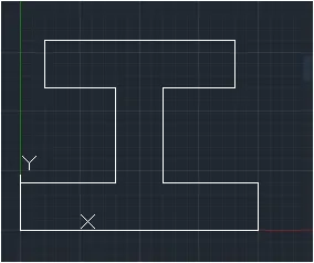
VI.Drafting the geometry for P8 by using Relative Rectangular Coordinate System:
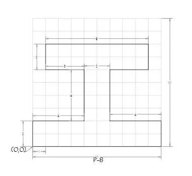
Steps:
- Select the line tool from the ribbon or by entering the 'line'command in the command tab.
- Specify the next coordinate of point 1 as 0,0
- Specify the next coordinate of point 2 as @10,0
- Specify the next coordinate of point 3 as @0,2
- Specify the next coordinate of point 4 as @-4,0
- Specify the next coordinate of point 5 as @ 0,4
- Specify the next coordinate of point 6 as @3,0
- Specify the next coordinate of point 7 as @ 0,2
- Specify the next coordinate of point 8 as @-8,0
- Specify the next coordinate of point 9 as @0,-2
- Specify the next coordinate of point 10 as @ 3,0
- Specify the next coordinate of point 11 as @0,-4
- Specify the next coordinate of point 12 as @ -4,0
- Then for the last point ,Click'Close' on the command line.
Result:
VII.Drafting the geometry for P9 by using Absolute Coordinate system:
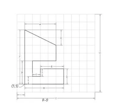
Steps:
- Select the line tool from the ribbon or by entering the line command in the command tab.
- Specify the next starting coordinate of point 1 as 1,1
- Specify the next coordinate of point 2 as 6,1
- Specify the next coordinate of point 3 as 6,3
- Specify the next coordinate of point 4 as 3,3
- Specify the next coordinate of point 5 as 3,2
- Specify the next coordinate of point 6 as 2,2
- Specify the next coordinate of point 7 as 2,4
- Specify the next coordinate of point 8 as 5,4
- Specify the next coordinate of point 9 as 5,6
- Specify the next coordinate of point 10 as 1,8
- Then for the last point Click 'Close' on the command line.
Result:
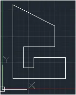
VIII.Drafting the geometry for P10 by using Relative Polar Coordinate System:
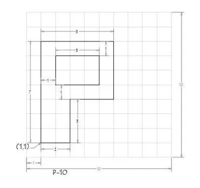
Steps:
- Select the line tool from the ribbon tab or by entering the 'Line' command in the command tab.
- Specify the starting coordinate of point 1 as 1,1
- Specify the next coordinate of point 2 as @ 2<0
- Specify the next coordinate of point 3 as @3<90
- Specify the next coordinate of point 4 as @4<90
- Specify the next coordinate of point 5 as @4<90
- Specify the next coordinate of point 6 as @ 5<180
- Click"Close' on the command line.
- Specify the next coordinate of point 7 as 2,5
- Specify the next coordinate of point 8 as @3<0
- Specify the next coordinate of point 9 as @2<90
- Specify the next coordinate of point 10 as @3<180
- Then for the last point ,Click 'Close'on thhe command line.
Result:
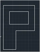
Civil Related Problems:
B) To Draw the profilr and the trusses using any coordinate system methods.The dimensions are there for the reference:
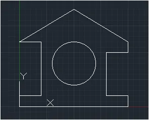
I.Drafting the Wood Profile as shown in the given picture:
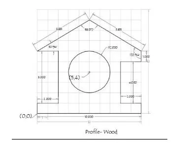
Steps For Creating The Wood Profile Using Direct Distance Entry Method:
- Select the line tool from the ribbon tab or by entering the 'Line' command in the command tab.
- Specify the starting coordinate of point as 0,0 in the command line.
- Enter the length of point 2 as 10 in the command line towards the +ve x-axis.
- Enter the length of point 3 as 1 in the commnad line towards the +ve y-axis
- Enter the length of point4 as 2 in the command line towards the -ve x-axis
- Enter the length of point 5 as 4 in the command line towards the +ve y-axis
- Enter the length of point 6 as 2 in the command line towards the +ve x-axis
- Enter the length of point 7 as 1 in the command line towards the +y-axis
- Enter the length of point 7 as 5.831 in the command line at an angle <149.036 from + ve x-direction while keeping polar tracking on.
- Enter the lemgth of point 8 as 5.831 in the command line at an angle <210.964 from the +ve x- direction while keeping polar tracking on.
- Enter the length of point 10 as 5 in the command line towards the -ve y-axis.
- Enter the length of point 11 as 2 in the command line towards the +ve x-axis
- Click'Close'on the command line.
- Select the circle tool by entering the 'Circle'command in the command tab
- Specify center point of the circle as 5,4
- Specify radius of the circle as 2
Result:
II.Drafting the Queen Post Truss as shown in the Given image:
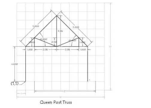
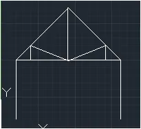
Steps For Creating The Queen Post Truss Using Relative Polar Coordinate System:
- Select the line tool from thr ribbon or by entering the line command in the command tab.
- Specify the starting coordinate of point 1 as 1,1
- Specify the next coordinate of point 2 as @4<90
- Specify the next coordinate of point 3 as @5<45
- Specify the next coordinate of point 4 as @5<315
- Specify the next coordinate of point 5 as @4<270
- Press 'Esc' to cancle the line command.
- Select the line tool from the ribbon or by entering the Line command in the command tab
- Specify the starting coordinate of point 1 as 1,5
- Specify the next coordinate of point 2 as @1<0
- Specify the next coordinate of point 3 as @2.5355<0
- Specify the next coordinate of point 4 as @ 2.5355<0
- Specify the next coordinate of point 5 as @1<0
- Press 'Esc' to cancle the line command.
- Select the line tool from the ribbon or by entering the 'Line'command in the command tab.
- Specify the starting coordinate of point 1 as 2,5
- Specify the next coordinate of point 2 as @1<90
- Specify the next coordinate of point 3 as @ 2.7256<338
- Specify the next coordimate of point 4 as @2.7256<22
- Specify the next coordinate of point 5 as @1<270
- Press 'Esc' to cancel the line command.
- Select the line tool from the ribbon or by entering the 'Line'command in the command tab
- Specify the starting coordinate of point 1 as 4.5,5
- Specify the next coordinate of point 2 as @ 3.53571<90
- Press'Esc'to cancel the line command.
Result:
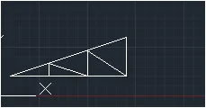
III.Drafting the Mono Pitch as shown in the given image:
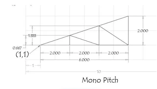
Steps For Creating The Mono Pitch Using Absolute Coordinate system:
- Select the line tool from the ribbon or by entering the 'Line'command in the command tab.
- Specify the starting coordinate of point 1 as 1,1
- Specify the next coordinate of point 2 as 7,1
- Specify the next coordinate of point 3 as 7,3
- Click'Close' on the command line.
- Select the line tool again from the ribbon or by entering the 'Line'command in the command tab.
- Specify the starting coordinate of point 4 as 3,1
- Specify the next coordinate of point 5 as 3,1.667
- Specify the next coordinate of point 6 as 5,1
- Specify the next coordinate of point 7 as 5,2.3333
- Specify the next coordinate of point 8 as 7,1
- Press 'Esc'to cancel the line command.
Result: