To Analysis and Design of Steel Structures using TSD
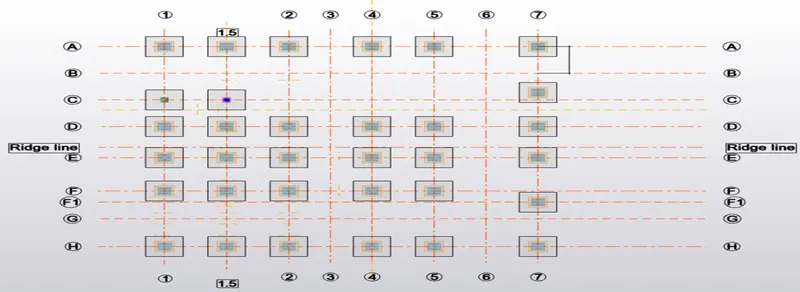
Above is the Layout plan of my model in which from left to Right side represents +X axis while from Bottam to top of the screen shows + Ve Y axis.
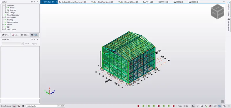
Due to Planar Irregularity from the Architectural point, this model is quite weak along the Y-axis force(Fy) orientation.
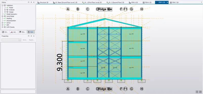 Frame 1
Here the opening is provided b/w C& D grid in Frame 1, where we are not getting any significant problem but,
7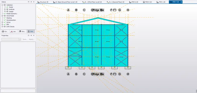 Frame 7
In Frame 7, Three opening/ door should be provided b/w C&D, D&E and E&F which makes our model unstable for the force acting along the Y axis.
Lateral Force provided in Frame 7 is susceptible to +21/14 mm deflection along X-axis while wind is blowimg along Y axis.(Out of plane Deflection)
(Analytical results are explained properly in PDf Attached below named as Model Deflection phenomenon due to primary load)
Though the structure/ Model can be made as per architectural viewpoint, but Good Architectural plan can be secured more easily and economically even by the Engineer of Pettty Skills but Bad Architectural plan can not be much justified even by a Good Engineer in Charge.
By Providing the Lateral bracing on either side of plane 7 above shown, we have to design the base plate of four columns for a tensile force of appro. 210 KN, data is shown in PDF attached below.
=============================================================================
Other frame plane named as Frame A and Frame H where we are not facing much irregularity is shown below:
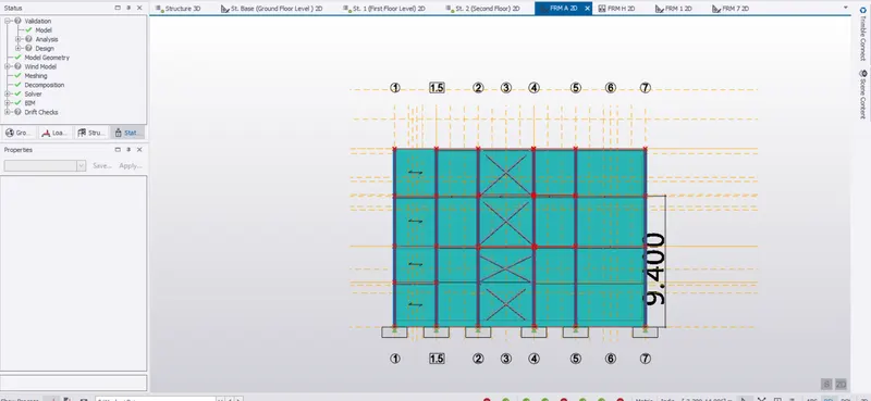
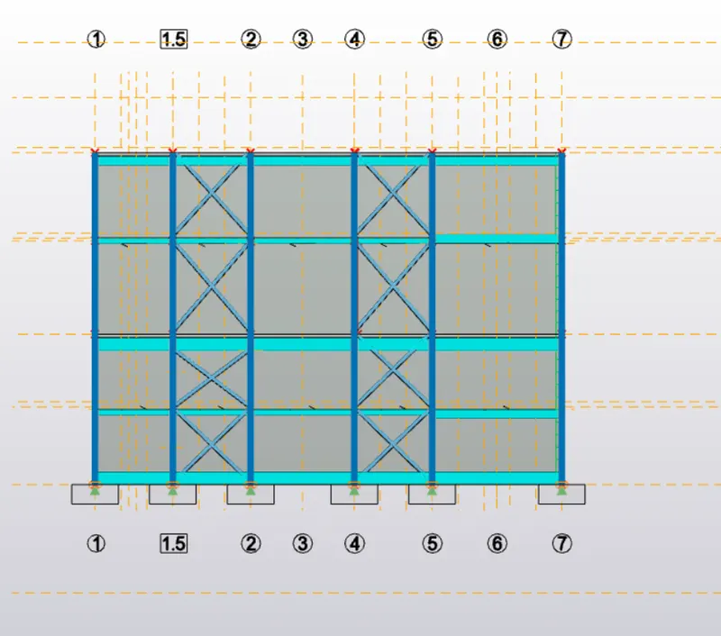
In Between 1 & 1.5 in Frame H, we have an staircase which completely change the centre of rigidity of this model resulting in unsymetrical lateral bracing system along the periphery of the Model.
=================================================================================
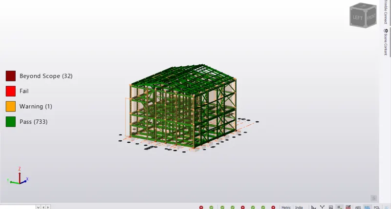
1. Even after the unsymmetry in Model plan, Wind Direction reversibilty hardly provide a change in reaction's Magnitude, though its nature get changed due to change in orientation.
2. More than 95% of Lateral force acting on the system, is resisted by the bracing system installed along both the Axis.
3. Due to Y axis force action, out of plane deflection in the lateral force resisting system installed along the Y axis, is crossing the maximum Drift limit.
4. max. deflection mentioned in above point is seen at the height of 9.3 m from the base of the building i.e. We are getting maximum drift not at an Extreme height of our model but at an intermediate level.
5. This nature give rise to the formation of Kink in our model at frame 7 at the height of 9.3 m whose data is shown in PDF attached below named as "Model Deflection Phenomenon due to primary loads".
6. Though all our members are passing, but model can be optimised if good plan is adopted.
Foundation IR ratioon basis of (available Bearing Preessure/ Max. Bearing Capacity)
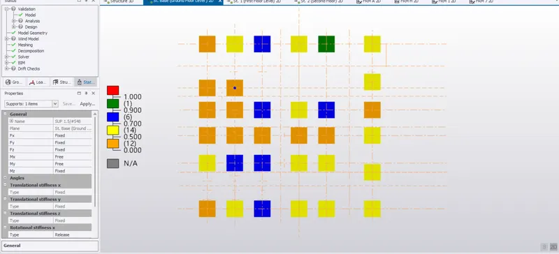
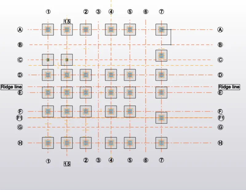
C7, H1.5 & H4 footing is designed under Top & Bottam R/f @16mm dia #125 mm C-C
while rest of the footing are designed under single Bottam R/f @ 16mm dia #125mm C-C
All Footing are of (1800*1800*750)mm.
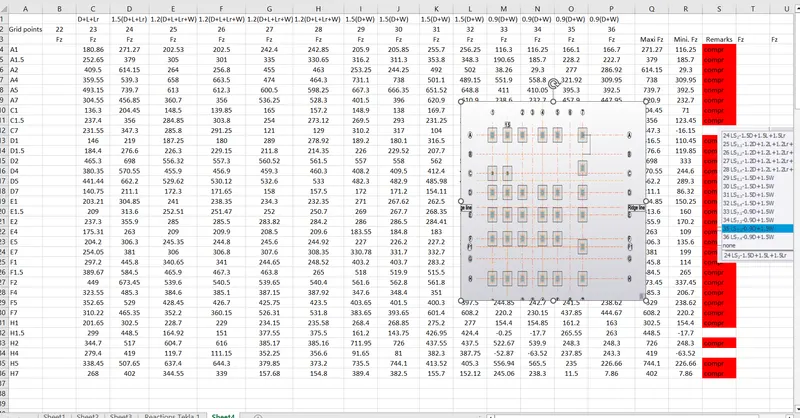
7. There is hardly 20% variation along the specific grid which minimises the chances of Differential Settlement which can be easily identified by looking at the screenshot below.
===============================================================================
Thanks & Regards,
Please let me know about my mistakes or ill habits while looking at our model so that I can lucratively utilise my skills for the upliftment of Mankind.
Thanks once Again!