To Analysis and Design of Steel Structures using TSD
1.
Aim: To summarise the study for bending moment, shear force and deflection diagrams for the elements of the model
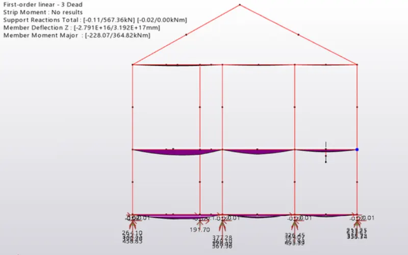
Bending Moment
- Bending Moment refers to the bending of member due to the applied forces.
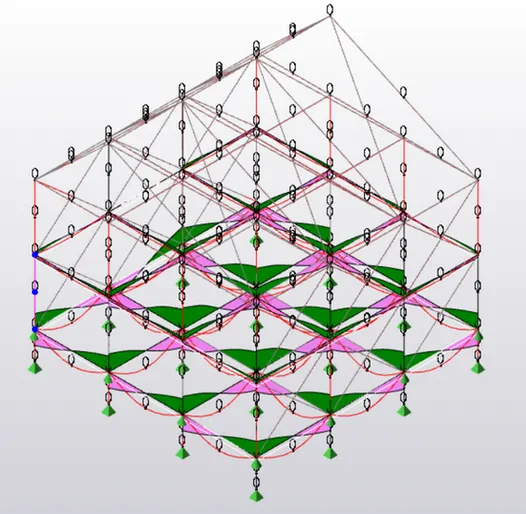
- Now in our figure, we can see the simply supported beams subjected to certain uniformly distributed load and the bending moment values.
- All the supports are hinged so the reaction at the end is zero.
- And the concave shape at the centre represents the bending of the beam due to applied load
Shear Force
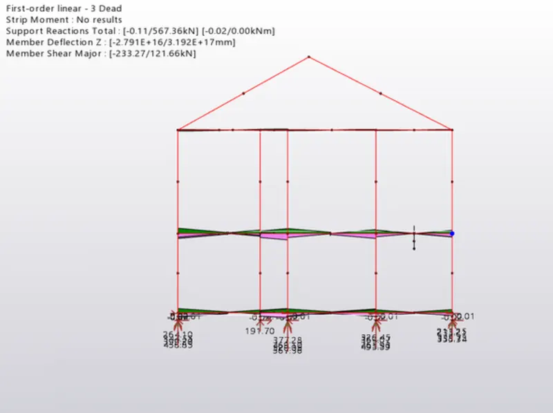
- Shear force is defined as system of two equal and opposite forces acting side by side or at close distance, and this occurs at the supports of a beam where there will be upward force applied at ends and reactions will be developed at the bottom, hence creating a system of two equal and opposite forces.
- In our figure, we can observe that the figure reaction is maximum at the ends and zero at the centre
Deflection Diagrams
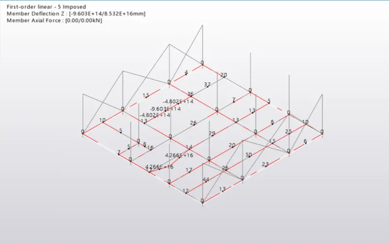
- Deflection diagram refers to the settling or deformation of the structural members such as beams and columns.
- Deflection means the components move from their original place to some extent due to the applied forces
- Allowable deflection is Span/250, if it exceeds than this value, then the dimensions of the members should be changed.
2.
Aim: To outline the thought process in selecting the member sizes along with the foundation design
Procedure:
- From the ribbons, select seismic wizard and select the code spectra
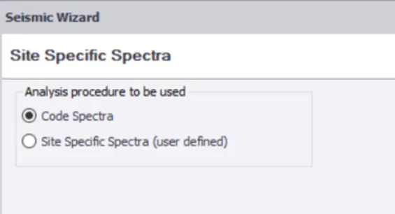
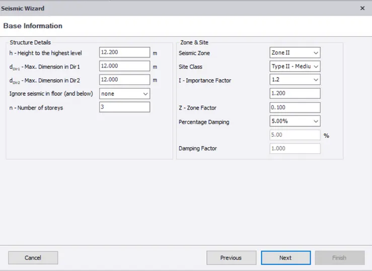
- Now in a table, all the values will be shown by the software except the zone and the importance factor, now click next
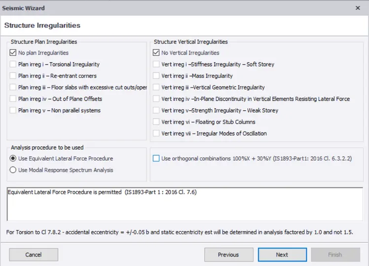
- Now tick on No plan irregularities option in both the columns and click next
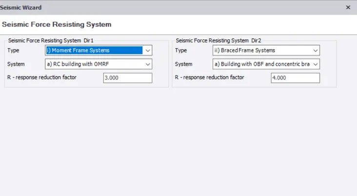
- Now enter the strure type as steel composite structure and click next and select the moment frame as OMRF and enter the response reduction factor and click Next
- Now enter the load cases and click ok.
- Now go to the load combinations and click Generate option.
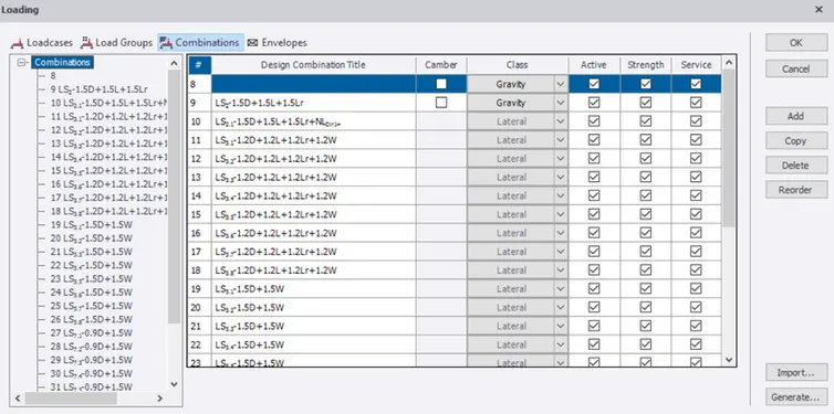
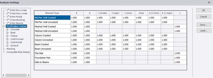
- Now from the Analyze tab, select first order analysis after setting the modification factor as 1
- Now start checking the members for design and select any one member and right click on it. Select the check member a list will be obtain and check if it passes all the condition.
- If it fails, click on the criteria and correct it by increasing the size.
- This procedure is repeated for all the members and design is complete and then, display the shear force and bending moment diagram
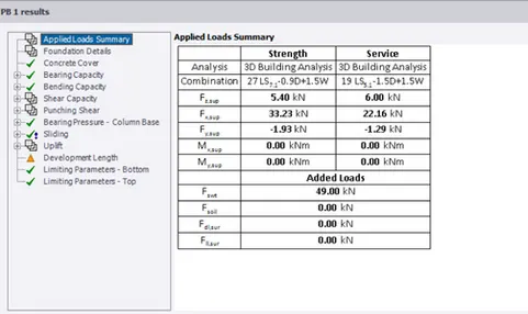
- Now for designing Foundation, fo to the foundation tab and select base pad and assign it to any one column.
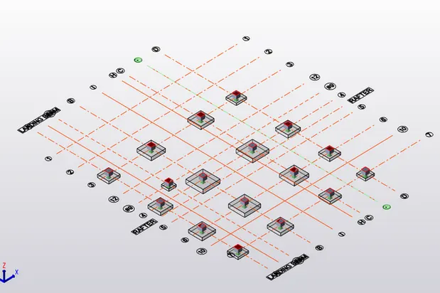
- Initially assume the dimensions and check the foundation for design
- Here, we assumed the same to all the columns