Temperature & Contact Area for Heat Dependance on an EV Battery Pack using Simulink
OBJECTIVES:
- Prepare a report summarizing the Thermal Management Techniques for Electric Car Battery Pack.
- Create a Simple Simscape Model with a Battery and show the Temperature Dependence in the Performance. Also connect a Resistor Load of 10 Ohm.
(Hint: Table-based Battery, Temperature Source)
- Compare the Resultants Graph for Different Area of Contact of Heat.
SOLUTIONS:
Solution to Objective 1:
In EVs and HEVs, the Battery Pack along with other Electronic & Electrical Components and Systems can significantly affect the performance and Life Cycle of the Battery and its associated systems. Therefore in order to keep the Battery operating at ideal Temperature Ranges, Thermal Management Systems need to be implemented under the hood of EVs and HEVs. Thermal Management Systems help to minimize the discrepancy between the operating and optimum conditions of the Batteries and other Electronic & Electrical Components & Systems.
The Cooling Methods employed for the Batteries in EVs and HEVs are as follows:
- Passive Air Cooling System: As the name suggests, the cooling of the Batteries (in warm ambient conditions) is done by the Conditioned Air (emanating from the AC(s)). It is a highly effective Cooling Method for the Battery at mild temperatures (10°C-30°C) without the use of any Active Cooling Components. This method is also very efficient as it uses the air from the Vehicle Air Conditioning. The ideal Battery Operating Temperature (for Li-Ion Batteries) is approximately 20°C on the low end, which is highly compatible with the Cabin Temperature. However, Air Conditioning systems are limited by the Cabin Comfort levels and Noise Consideration, as well as dust and other Contaminants that might get into the Battery, especially when air is taken from outside.
- Active Air Cooling System: Similar to the Passive Air Cooling System, the only difference between the Active Air Cooling System & the Passive Air Cooling System is that in the Active Cooling System, the Air for cooling the Battery is drawn from a separate Micro Air-Conditioning Unit instead of the Vehicle Cabin. The Micro Air-Conditioning Unit is solely for the purpose of cooling the Battery. The Cool Air is drawn from the this micro Air-Conditioning Unit with the use of the available refrigerant. Even though this may provide more adequate cooling to the Battery, the Energy Consumption as well as the Cost and Space Requirements associated with installation of the Blower and the micro Air Conditioning Unit increases significantly.
- Series Air Cooling Technique: In Series Cooling Technique, the entire Cooled Air flows over the Module as a Single Unit. If the Entire Battery is large compared to the portion of region of the Battery that is in direct Contact with the Cooled Air, then the Cooling Process and hence the Temperature Distribution in the Battery Pack tends to non-uniform as only a particular Portion of the Battery Pack is in contact with the Cooled air while the other portions of the Battery Pack are not.
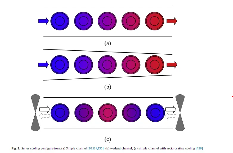
Series Cooling Technique of Modules (Top View)
- Parallel Air Cooling Technique: The Cooled Air for cooling the Battery Pack is split into equal portions where each portion flows over a single module of the Battery Pack. Thus in general, Parallel Airflow provides a more uniform Temperature Distribution than Series.

Parallel Cooling Technique (Top View)
Sometimes the Series Cooling Technique and the Parallel Cooling Technique are combined together to obtain the advantages of both the Cooling Techniques and effectively cool the Battery.
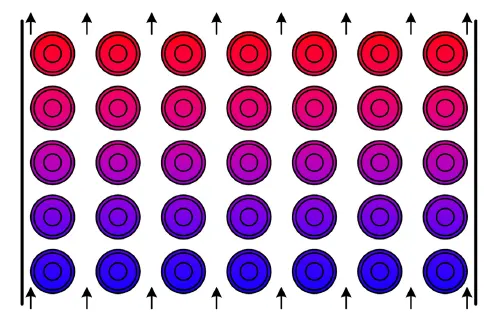
Series-Parallel Cooling Technique (Top View)
- Refrigerant Cooling Technique: It is a compact Cooling Technique of Battery and is more flexible than the Air Cooling Techniques as in this case, the Battery Evaporator is connected in parallel to the Evaporator in the Cooling Loop. The Heat generated from the Battery is transferred to the Evaporating Refrigerant. Generally, this systems require only two additional Refrigerant lines, namely Suction and Pressure lines. The Battery evaporator uses some portion of the Compressor Output (in the Refrigeration Cycle) that was reserved for the Air Conditioning, and thus this might cause conflict in some conditions. However, the Compressor work needed to cool the Battery is usually considerably lower than the Compressor Work, that the Refrigeration Cycle for Air Conditioning needs.
- Liquid Cooling Technique: In the Liquid Cooling Technique, the System incorporates the Refrigerant Cooling Technique with an additional Cooling Loop specifically for the Battery that connects to the Refrigerant. This additional Cooling loop usually has water or a 50/50 Water-Glycol Mixture and it is kept cool via different procedures depending on the Cooling Load and ambient conditions. The coolant can be cooled either by ambient air through the battery cooler (if the ambient temperature is low enough) or by transferring the heat to the refrigerant through the chiller. Both methods increase the efficiency of the system since the additional compressor work (that is used in refrigerant cooling) is no longer needed.
- Phase-Change Materials Integrated Cooling Systems: These Thermal Management Systems have a significant advantage over the other Thermal Management Systems due to its simple design, light weight and compact size, safety and relatively low cost. Using PCM Materials for Cooling is again a Passive Cooling Technique. This Systems derive the Heat from the large amount of Latent Heat of the Phase Change Materials when they are undergoing a Phase Change. This Latent Heat is used to heat the Batteries (when the Battery Pack is at Standby State i.e. neither Charging nor Discharging) at the required Optimum Temperature necessary for the proper functioning of the Battery and its Life Cycle.
During Battery Charging & Discharging, when the Temperature of the Cells in the Battery Pack rises, the PCM (Phase Change Materials) act as a Heat Sink for the heat generated from the Cells.
The PCM Systems can act as a both primary or secondary role in Thermal Management of the Battery Packs which can reduce the cost and complexity of the system.
Solution to Objective 2:
The Simscape Model with a Battery showing the Effect of Temperature (Ambient & Cell) on the performance of the Battery.
The Blocks used for modelling this Battery are as follows:
- Solver Configuration Block: The Solver Configuration block specifies the solver parameters that your model needs before you can begin simulation. Each topologically distinct Simscape block diagram requires exactly one Solver Configuration block to be connected to it.
- Electrical Reference: A model with electrical elements must contain at least one Electrical Reference block. Since this Simscape Model contains many Electrical Blocks, hence an Electrical Reference is necessary to be connected to the network joining the Electrical Blocks.
- Thermal Reference: The Thermal Reference block represents a thermal reference point, that is, a point with an absolute zero temperature, with respect to which all the temperatures in the system containing all the Simscape Thermal Blocks, are determined.
- Battery (Table-Based) Block: The Battery(Table-Based) Block is used to for modelling the Battery and analyse it’s behaviour w.r.t Temperature.
The parameters given to the Battery(Table-Based) Block are as follows:
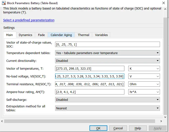
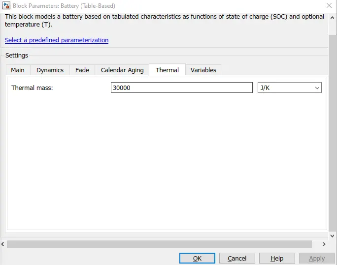
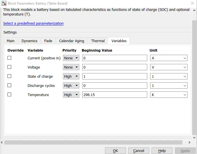
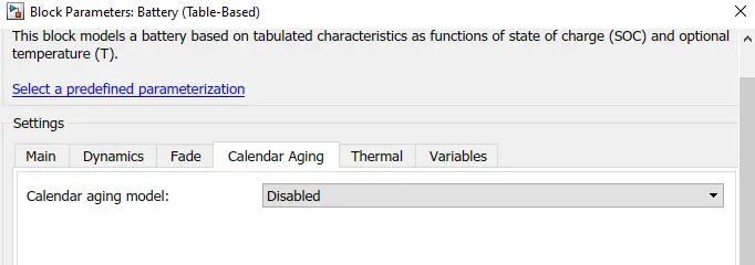
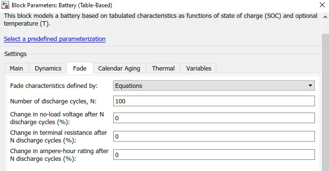
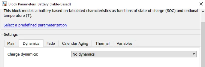
Battery Block Parameters for Modelling the Battery
Also, the ‘Instrumented| Show Thermal Port’ is chosen as the Block Choice for this Simscape Block. This enables a Temperature Dependent Battery Block and will enable us to see the effect of Temperature on the Model.
- Controlled Current Source Block: This Block is used to represent a Current Source which when connected to an Electrical Circuit generates Current in the Circuit on the basis of an input Signal fed to the Block.
- Constant (Simscape Block): This Block generates a constant output value as per the value set inside this Block. In this Model, the Constant Block is used to generate the Current Signals for the Controlled Current Source Block. For this Model, the Constant Value represents the Current that will Flow through the Circuit. The Constant Value has been taken as 2.1 which means that the 2.1 Ampere Current will flow through the Circuit because in general, the recommended Charge/Discharge Rate of the Battery should be 0.5 C Rate. Since the maximum Rated Capacity of the Battery is 4.2 Ah and the Simulation Time is taken as 60*60=3600 seconds=1 Hour, therefore in order for the Battery to charge/Discharge at 0.5 C Rate, the Current flowing from/to the Battery through the Circuit is 4.2*0.5=2.1 Amperes.
- Temperature Source Block: The source generates constant absolute temperature, defined by the Temperature parameter value which is set as 293.15 K. The Outlet Temperature from this Block is powerful enough to keep it constant at all costs.
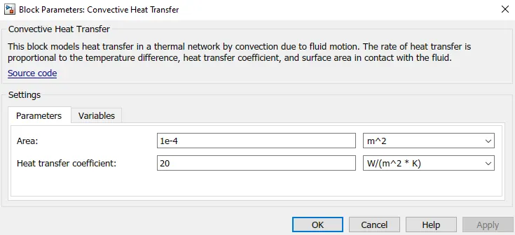
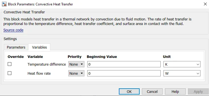
- Convective Heat Transfer Block: This Block represents a Convective Heat Transfer between 2 bodies by means of Fluid Motion governed by the Newton’s Law of Cooling. The Parameters given to the Convective Heat Transfer Block are as follows:
*
Convective Heat Transfer Parameters
- Temperature Sensor Block: This Block represents an Ideal Temperature Sensor which measures the Temperature Difference between any 2 points without allowing any heat flow into the Sensor.
- Thermal Reference Block: This block represents a reference point in a thermal network where the temperature is equal to absolute zero.
- Resistor Block: The Resistor Block models a Constant Linear Resistor which can be described by the following mathematical equation:
V=I*R
Where V is the Voltage/Potential Difference across the Resistor.
I is the Current flowing through the Resistor
R is the Resistance
- Scope Block: It plots & displays the Signals fed as an input to the Block w.r.t. time.
- To & From Blocks: The ‘To Blocks’ are used to pass the input values to the ‘From’ Blocks without directly/physically connecting the Blocks.
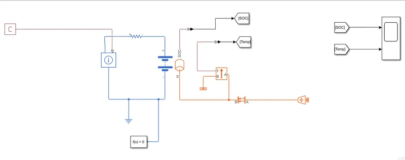
My Battery Model Picture
As can be seen from the Model, the Temperature of the Battery varies as the Battery is getting discharged.When the area of Contact of Convective Heat Transfer is set to 1 X 10⁻⁴ m2, then the Temperature of the Battery rises as the Battery Discharges.
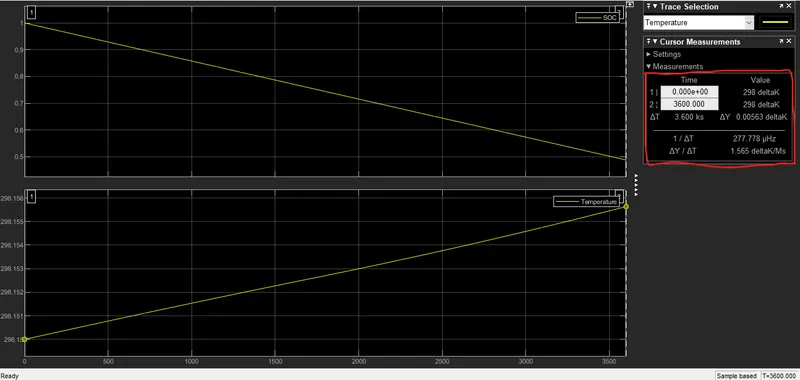
SOC and Temperature Characteristics of the Battery for Convective Surface Area of 1 X 10⁻⁴ m2
Solution to Objective 3:
In Convection, the Heat Transfer takes place via transfer of Heat through Conduction & Fluid Flow. In Conduction, the Energy is transferred from more Energetic Particles of a substance to the adjacent less Energetic ones. In Liquids and Gases, Conduction is due to collisions and diffusion of molecules during their random motion.
In the Battery Model, the Heat Transfer takes place via Convection between the Temperature Source Block (maintained at 20°C/293.15 K) and the Battery (set at 298.15 K/25°C at Fully Charged Initial State).
The following are the Plots Obtained for various Surface Areas through which Heat Transfer takes place:
SOC and Battery Temperature Plots for Surface Area 1=1 X 10⁻⁴ m2
SOC and Battery Temperature Plots for Surface Area 2= 0.2 X 10⁻³ m2
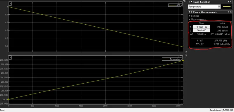
SOC and Battery TemperaturePlots for Surface Area 3= 0.5 X 10⁻³ m2
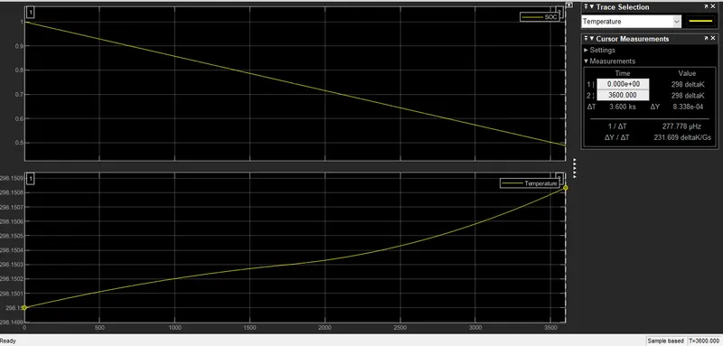
SOC and Battery Temperature Plots for Surface Area 4= 0.55 X 10⁻³ m2
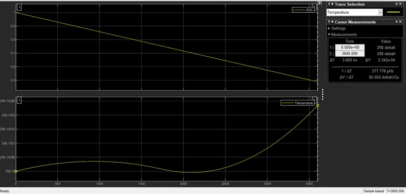
SOC and Battery Temperature Plots for Surface Area 5= 0.6 X 10⁻³ m2
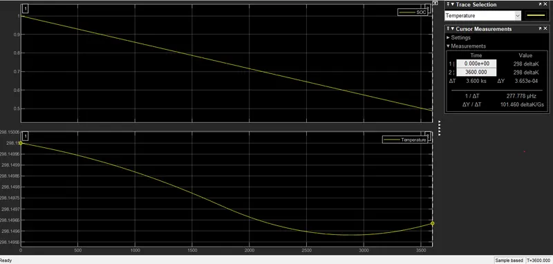
SOC and Battery TemperaturePlots for Surface Area 6= 0.8 X 10⁻³ m2
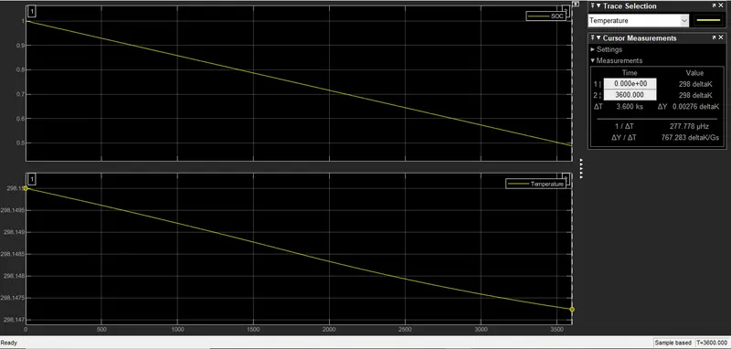
SOC and Battery TemperaturePlots for Surface Area 7= 1 X 10⁻³ m2
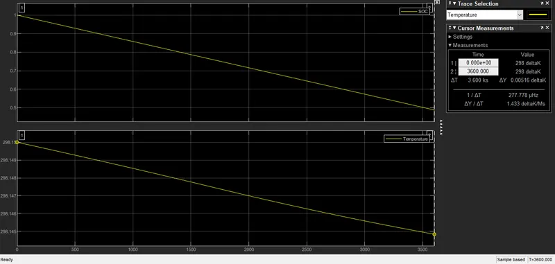
SOC and Battery TemperaturePlots for Surface Area 8= 0.5 X 10⁻² m2
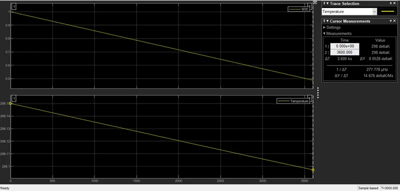
SOC and Battery TemperaturePlots for Surface Area 9= 1 X 10⁻² m2
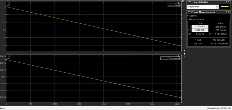
As can be seen from the Plots, when the Surface Area for Convective Heat Transfer is lower, the Temperature of the Battery (being measured using a Temperature Sensor) rises as the Battery Capacity/SOC of the Battery starts decreasing because the Surface Area for the Heat Dissipation is not large enough to dissipate the Heat throughout the Medium/Body to which the Heat is transferred convectively.
But as the Surface Area for Convective Heat Transfer is increased, then Area for Heat Dissipation increases and then the Rate of Temperature Increase of the Battery (being measured using a Temperature Sensor) starts decreasing until the Temperature becomes somewhat Constant and then Temperature starts decreasing, as the Battery discharges as the Surface Area for the Heat Dissipation is large enough to dissipate the Heat throughout the Medium/Body to which the Heat is transferred convectively.