Study of Torque-Speed Characteristics of DC Machine
AIM –
- Develop a MATLAB Code for D.C. Machine and visualize its Speed and Torque Characteristics.
- Distinguish between cables used in wiring HEV.
- Brief on High and Low Voltage in EV.
INTRODUCTION:-
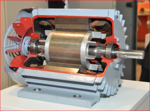
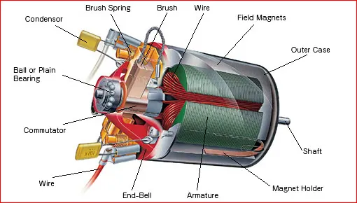
A D.C.Machine is an electromechanical energy alteration device. The working principal of a D.C.Machine is when electric current flows through the coil within a Magnetic Field and then the Magnetic force generates a torque which rotates the D.C.Motor.
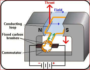
The D.C.Machine can be classified into 2 types namely D.C.Motors as well as D.C.Generator.
D.C.Motor is used to convert Electrical Energy into Mechanical Energy. The shaft of the motor rotates when current is supplied to the motor. Motors are used to operate pumps, lift, Cranes etc. the construction of D.C.Motor is similar to D.C.Generator.
When the Armature and Field Winding of a D.C.Generator is connected to D.C.Source (e.g -Battery) it will work like Motor.
The Advantages of D.C.Motors includes low initial cost, Ease in speed control, High initial Torque
Types of D.C.Motors
D.C.Motors can be classified into 3 types according to the connection of field winding to the Armature winding.
- Shunt Wound motor.
- Series Wound motor.
- Compound wound motor.
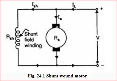
i. Shunt Wound motor:
Here the Field winding are Connected in parallel with the Armature.
For the Constant applied Voltage, the field current is Constant.
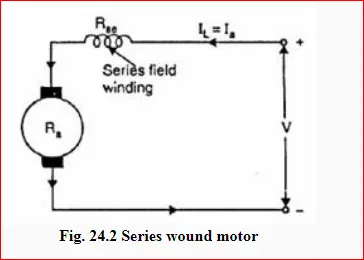
The speed of the shunt wound makes it almost constant as the Flux and Back EMF are constant. Therefore it is also called as constant speed machine.
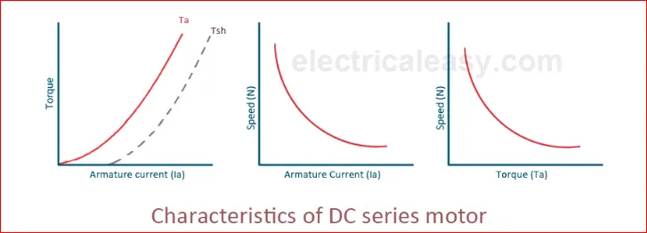
ii.Series wound motor:
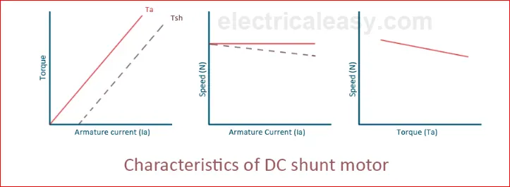
Since the Field winding and Armature are connected in series.
`I_field=I_Armature`
One of the characteristics and advantage of D.C.Motor is that as the motor is loaded heavily, the speed of the motor automatically get reduce.
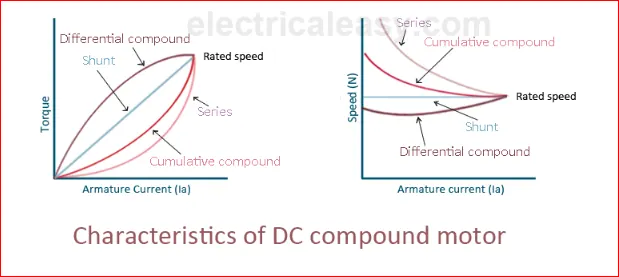
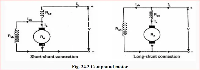
iii. Compound wound motor the Field pole winding comprise of two windings.
- Shunt Field Winding.
- Series Field Winding.
The field windings connected in series and shunt this produce the resultant flux to drive the motor. D.C.Motor is the combination of series and shunt motor. The series field winding is connected in series with the armature and shunt field is in series with the armature and a shunt field is in parallel with the armature. The combination of series and shunt winding allows the motor to have the torque characteristics of the series motor and the regulated speed characteristics of the shunt motor.
Back E.M.F in D.C.Motors
When the motor is operated magnetic flux is produce by field winding and armature winding. The flux produced at the field winding is also known as main flux. As the armature rotates the winding of the armature (also known as conductors) cuts the flux. Thus E.M.F is induced in the armature winding whose direction is opposite to the applied voltage. The induced E.M.F is in opposite direction and opposes the applied voltage, it is also known as back E.M.F.
Thus the relation between applied voltage and back E.M.F is given as follows.
`V= E_b + I_a R_a`
Where,
`V=applied voltage`
`E_b=Back E.M.F`
`I_a=Armature Current`
`R_a=Armature resistance`
MOTOR TORQUE:
It is also known as moment of force. Torque is the tendency of a force to rotate an object about an axis or pivot. Force is defined as Push or Pull; similarly a torque can be thought of as a twist.
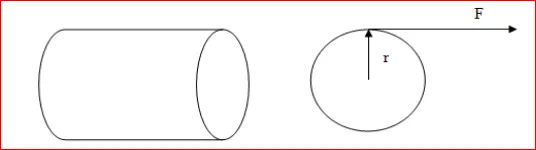
Consider a shaft of radius “r” which is rotated by its axis by force “F” acting on circumference of the shaft.
`T= r × F`
Where,
`T=Torque`
`r = radius of shaft`
`F= Applied force`
MACHINE TORQUE:
One of the basic specifications of an engine is Torque. The power output of an Engine can be given as:
`Power developed (P)=Torque × Rotational Speed`
`P = T × ω watt`
`P=T × 2πN/60` ………………. (Eq.no 1)
Where,
`P = Power developed`
`T= Torque`
`ω = Angular velocity in rad/sec`
`N=rpm (rotation per min)`
TORQUE IN MOTOR:
From equation 1 power developed is given as:
`P=T_a × 2πN/60` ……………….. (Eq.no 2)
`T_a=Torque developed by armature`
Electrical equivalent of mechanical power developed by the armature is given by
`P= E_b I_a watt` ……………… (Eq.no 3)
`E_b=Back E.M.F`
`I_a=Armature current`
`T_a ×2πN/60=E_b I_a` ……………….. (Eq.no 4)
Back E.M.F `E_b=(∅ZN)/60 p/a` .............(Eq.no 5)
Where,
`∅= (flux)/(po l e i n weber's)`
`Z=Total number of armature condutor`
`N=Armature rotation R.P.M`
`p=number of poles`
`a=number of parallel path in armature`
Placing value of equation (5) into equation (4)
`T_a × 2πN/60= (∅ZN)/60 p/a I_a`
Arranging,
`T_a=0.159 ∅ Z I_a p/( a)`
Since Z,p and a are constant for any motor
`T_a α〖 ∅I〗_a`
Torque-Speed Characteristic of a DC machine:
The Equation is given by
`T=V .k ∅/R_a - ((〖k∅〗^2 ))/R_a .N`
Where,
`k∅ = E_(b ).60/(2πN_s )`
T = Torque.
V = Voltage Supply.
`k∅ =` Constant of proportionality.
`R_a=` Armature Resistance.
N = Motor Speed in rad/sec.
OBJECTIVE-1
Develop a MATLAB Code for D.C. Machine and visualize its Speed and Torque Characteristics.
The equation is implemented in the MATLAB to study the Torque speed Curve of DC Machine.
MATLAB CODE:
clear all
close all
clc

% Torque Speed Characteristics of DC Machine.
% Array of motor speed in rad/sec
Speed  = linspace(0,500,50);

% Input of Speed constant of a motor  (rpm/v)
N_s   =  input('Enter the value of Speed Constant of Motor = ');

% Input the Battery voltage supply value.(volts)
V   =  input('Enter the value of Voltage Supply = ');

%Input the Armature Resistance. (ohms)
R_a  =  input('Enter the value of Armature Resistance = ');

% Back E.M.F developed
EMF  =  1 ;  % back emf is directly proportional to speed constant given in the dat is per unit voltage

%Calculating the constant of proportionality in emf and speed relation
k_phi  =  (EMF*60)/(N_s*2*3.14);

% the DC motor Speed torque charateristics
% T = ((V*k_phi/R_a) - ((k_phi)^2/R_a)*omega)
% Calculation of Torque
 T  =  ((V*k_phi/R_a) - (((k_phi)^2/R_a).*Speed));


 % To calculate Total Current in Ampere
 TC  =  (V - EMF)/R_a;

 % To Calculate the maximum Torque
 T_max  = k_phi*TC ;


  %Convert Speed value in rpm from rad/sec
 Speed  =  Speed*60/(2*3.14);

 % Plotting the D.C.Machine charateristics w.r.t Speed Vs Torque
 plot(Speed,T,'color','r','linewidth',3);
 xlabel('Speed (RPM)');
 ylabel('Torque (Nm)');
 title('D.C.Machine Charateristics wrt Speed Vs Torque');
LINK FOR SCRIPT:https://drive.google.com/drive/folders/1IW5UlfplQOmip6UbjNAVdxUKio6ElerT?usp=sharing
EXPLANATION OF THE PROGRAM:
- First an array of 50 value of speed is taken by using the linspace command
- The input command is command so that MATLAB asks the user to enter the input data of voltage supply, speed constant of the motor and Armature resistance.
- Back EMF is directly proportional to motor speed , the motor speed constant given in the data is per unit voltage
Hence `E_(b )` will be 1.
- Then the calculation of the proportionality constant by entering the equation.
`k∅ = E_(b ).60/(2πN_s )`
- Now Entering the Torque Speed characteristic Equation to find the Torque for the array of 50 value of speed of the motor.
`T=V .k ∅/R_a - ((〖k∅〗^2 ))/R_a .N`
- Then the values Speed in Rad/Sec is converted to RPM by Multiplying 60/2`π`
- At last plot command is use to plot the speed torque curve which is a line as the torque speed equation is a line equation.
- The input value are entered manually.
RESULT's:
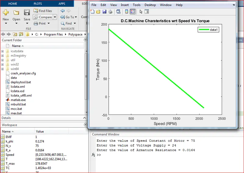
Result_1
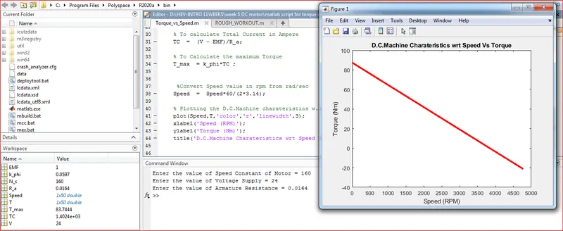
Result_2
OBJECTIVE-2
POWER CABLE AND SINGAL CABLE IN ELECTRIC WIRING OF VEHICLES:
POWER CABLE:
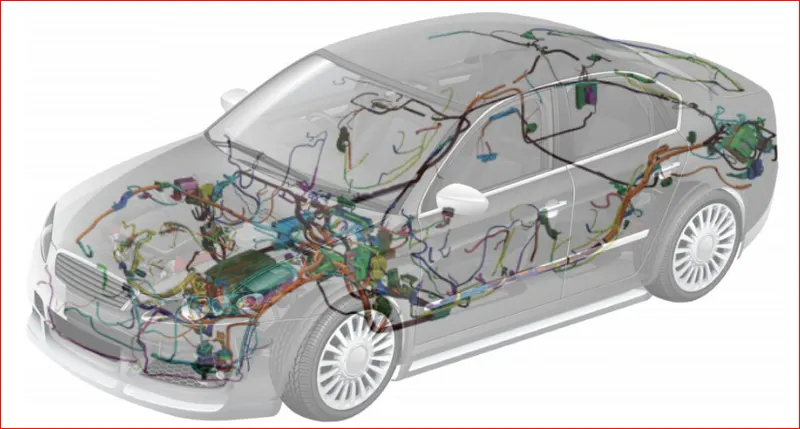
Power cable Are Use to transmit Electrical power, and are diametrically larger in size which will conduct maximum desired current through it. Also, they transfer both High and Low energy from the Source to Equipments. The External sheath of the Power Cable with its immense strength and Protection enable the cable to transfer High Volume without any Tension or Strain. Power cable often has a unique color code system that distinguishes the High Voltage carriers from the Low voltage counter parts.
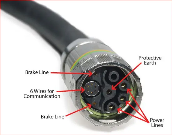
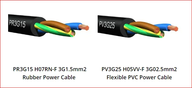
Power cables generally used to supply modern day electric application at huge level. Power cables connect the inverter with two 3 phase alternating current (AC) vehicle, one use for driving the vehicle while other is used for producing energy. The power cable has been 1st used by Toyota Prius that launched in Dec 2015.
SIGNAL CABLE:
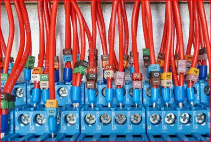
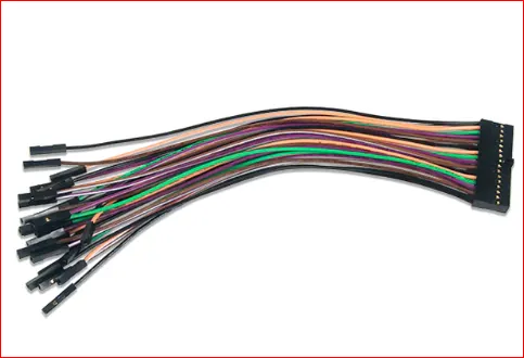
Signal Cables are used to transmit Electrical Signal used for Control that DATA transmission between Power Elements and Control Units. They are diametrically very small in Size when compared to Power cable. They are capable of transferring very low current required for trigger of electric signal or information. Usually use for region that require less than 1 ampere, this Signal can carry volt up to 40 Volts. These cables usually bear a PVC insulation that protects them from impact and harsh climate condition.
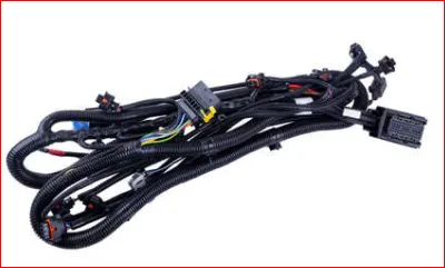
Signal cable are made up of metal wire or optical fiber which is use to transfer data. These cables are used in wire harnesses for various types of car door opening and closing and for automatic locking system of car. These are connected with Electronic control units and are used to transmit the signal to various parts of EV like Powertrain unit, Battery module, ABS etc. Signal cables are also used in Dashboard instrumentation signal.
The main difference between these two is power cable are use for powering the motors, Industrial machine, Large power transmitting cables, Signal cable are used for low and high analog signals such as RTDs, Filed instruments. Signal cables are used in test and measurements applications. If you are using 4 wire micro motion transmitter. Signal cable will carry 4 to 20 Ma Signal and Power Cable will carry 24DC/110/230Vac. Both cables cannot run on fixed route.
OBJECTIVE-3
What Voltage Level is considered as High & Low for a Battery Pack of Electric Vehicle?
Generally the Voltage for the Batteries are used in HEV’s and EV’s are classified as below,
|
Voltage Level |
Minimum |
Maximum |
|
HEV / Plugin Hybrid |
100 V |
200V |
|
EV |
400V |
800V |
|
Traditional |
12 to 14V |
|
|
Mild-Hybrid |
48V |
|
What’s make the Battery manufacturer to consider the High and Low Voltage or what parameters are considered to Grade the Battery for High and Low Voltage are:
- As we know the Battery Pack are combinations of several parallel cells which are formed to be a Battery Pack. The Lowest voltage through which the constant charge is passed on and is comfortably accepted by the cells together is majorly to be considered for Low and High voltage.
- Battery Temperature plays a vital role for the High and Low Voltage considerations.
- Type of Battery used.
- The High Peak point where the vehicle can be charge and does not affect drastically on the life of the Battery has to be considered.
- Types of operation from Battery.
- Charge to be withdrawn from the Battery and at what state the steady flow has to be achieved.
In these entire manner the Low and High Voltage are Designated to a Battery, as we all know Voltage is what that makes the Electric Charge move. So the Constant movement and maintain the surrounding has to be decided which is monitored by BMS Battery Management System.
CONCLUSION:
- At 0 Speed the Max Torque is obtained i.e. in our result observation we can see in Result_1 where T_max = 178.6547 at Speed = 0 and similar can be observed in Result_2 where T_max = 83.744 at Speed = 0.
- When the Torque becomes Zero, speed is max and at this point the commutator reverses the direction of current through the coil so the value of torque will be negative.
REFERENCE:
- https://www.electricaleasy.com/2014/07/characteristics-of-dc-motors.html
- https://www.aspina-group.com/en/learning-zone/columns/what-is/001/
- http://ecoursesonline.iasri.res.in/mod/resource/view.php?id=3305#:~:text=TYPES%20AND%20CHARACTERISTICS%20OF%20D.C.%20MOTORS%2DI,-Module%206.&text=D.C.%20motor%20is%20used%20to%20convert%20electrical%20energy%20into%20mechanical%20energy.&text=The%20advanta
- https://blogs.sw.siemens.com/ee-systems/2020/07/28/wiring-harness-development-in-todays-automotive-world/
- https://edisontechcenter.org/wires.html