Structural Modelling using Etabs 2018
AIM & INTRODUCTION :
AIM :
To design and analyse the G+7 residential building in zone 5 with the provided informations and the structural model must comply wiht provisions of IS 1893 and IS 13930.
INTRODUCTION :
- In E-TABS the stuctural members such as beams, columns and slabs can be created and analysed its bending moment and shear force.
- We can Run the Concrete Frame Design fo the created structure to provide required both Longitudinal and shear reinforcement bars automatically.
- The values for the created structures can be automatically calculated by E-TABS.
- Here in E-TABS we can know the number of Reinforcement bars should be provided for the concrete structures.
- From Frame design analysis we can see both Top and Bottom reinforcement figures for each beam sections.
- We can display concrete frame design result for Longitudinal and Shear reinforcement.
- And also for the Shear wall design such as Pier Longitudinal reinforcement, Pier Shear Reinforcemnt and Edge/Boundary Zone width.
- Moreover we can view the concrete beam design information as per IS 456:2000.
- The Design details of the overall structures can also be viewed as Summary, Flexural Details, Shear Details, Envelope.
- The Earthquake forces in both X and Y direction can be added and the deformations can be analysed.
- Likewise the Respond spectrum in X and Y directions can also be analysed.
- The shear wall stiffness and the base shear stiffness can be seen in the table after analysing.
PROCEDURE :
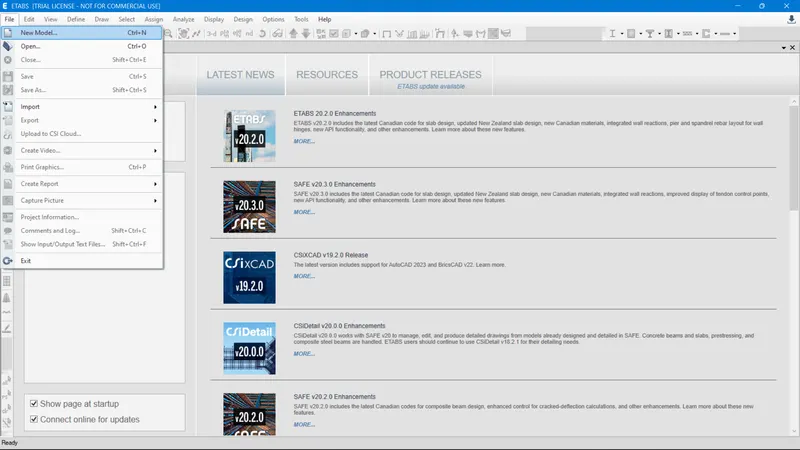
- First open the ETABS software and click File < New Model to open a new workspace to create a new Building model.
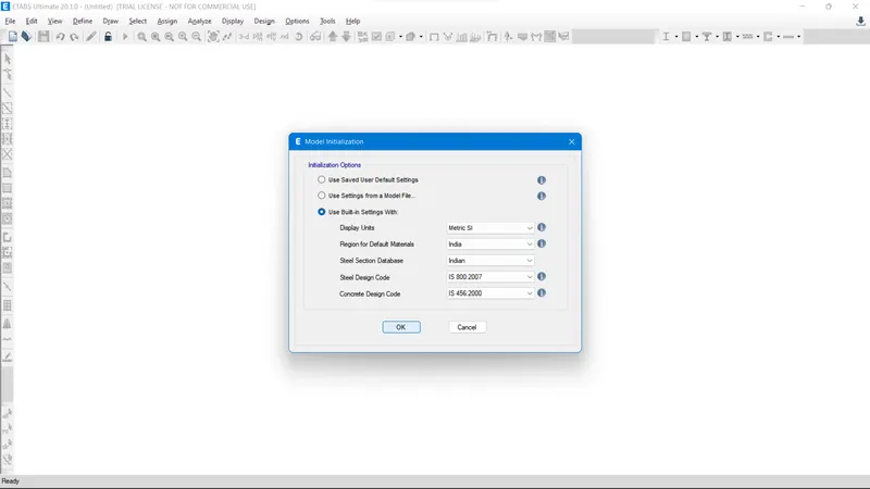
- Then the Model information Tab will be opened, there click Use Built-in Settings with.
- Followed by change Display Units = Metric SI, Region for Default Materials = India, Steel section Database = Indian, Steel Design Code = IS 800 2007, Concrete Design code = IS 456 2000 and click OK.
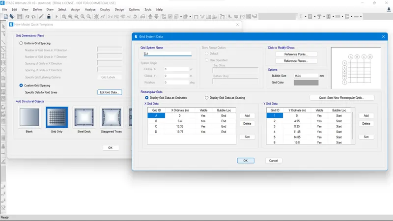
- After that the New model template Tab will be opened, there click Custom grid spacing < Edit grid data.
- Then the Grid system Data Tab will be opened, there in X Grid Data Add Grid ID = A,B,C,D with appropriate X-ordinates.
- Likewise in Y Grid Data Add Grid ID = 1,2,3,4,5,6 with appropriate Y-ordinates and click OK.
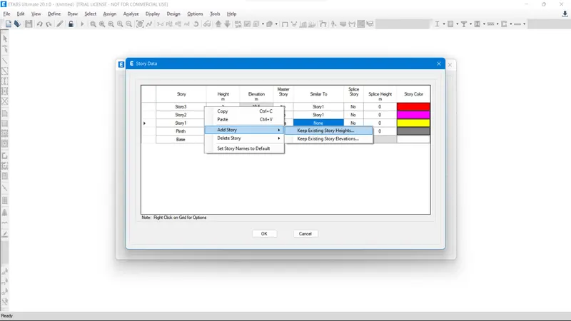
- After that the Story Data Tab will be opened, here to add extra required stories above the default stories.
- For that Right click over the last story and select Add story < Keep existing story heights.
- Now in Add story Tab add the Story height = 3 and the Number of Added stories = 7 and click OK.
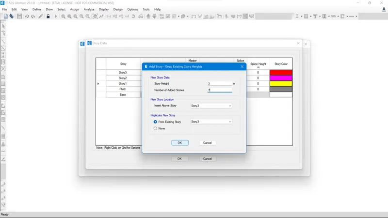
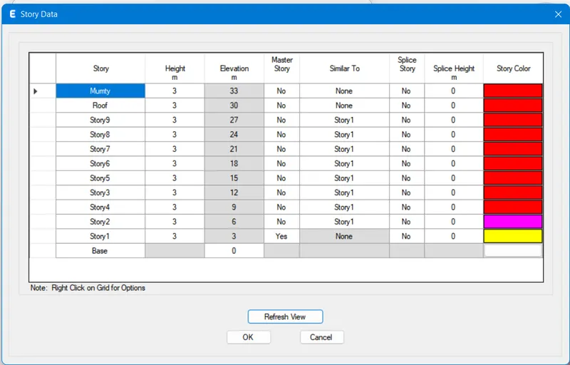
- Here we can see the extra stories are added above the previous story and we can give appropriate name to them such as from Base to Mumty.
- Then the Story 1 should be set as Master story and the remaining stories upto Story 9 should be set as Similar to story 1.
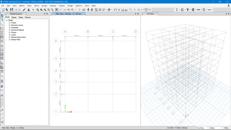
- Atlast the grids for all the stories can be created from Base to the Mumty level.
- Then we have to define the material properties for Columns, Beams, Slabs and Shear walls.
- For that click Define < Material Properties then the Define Materials Tab will be opened.
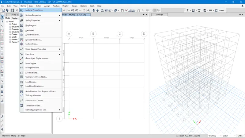
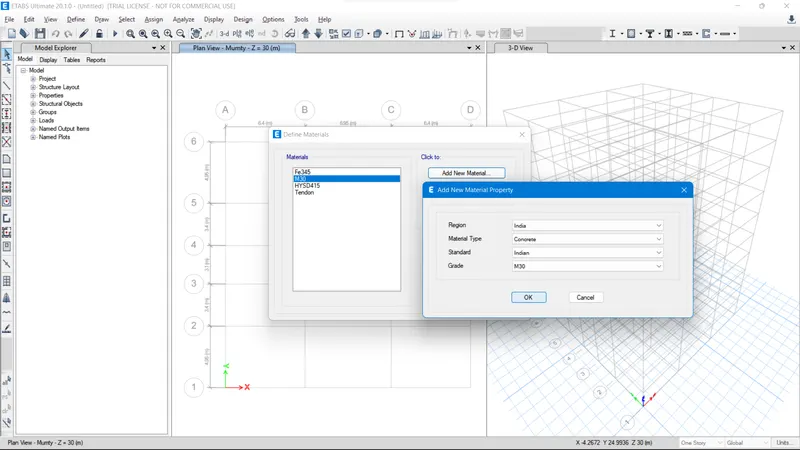
- In opened tab Click Add New material and select Region = India, Material Type = Concrete, Standard = Indian, Grade = 30 and click OK.
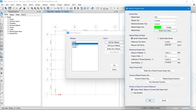
- Then Material Property Data Tab will open, here change the Material Name = M30, Material Type = Concrete and click OK.
- Likewise the Material property for Shear Rebar has to be defined.
- For that the same procedure should be followed such as click Define < Material Properties then the Define Materials Tab will be opened.
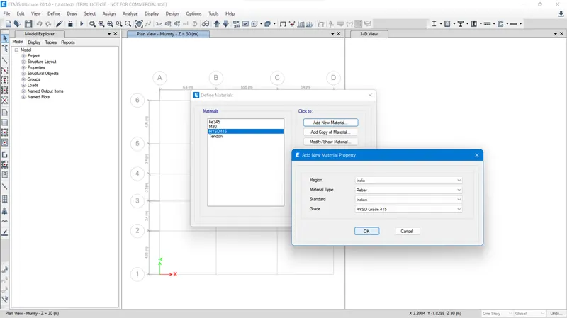
- In opened tab Click Add New material and select Region = India, Material Type = Rebar, Standard = Indian, Grade = HYSD Grade 415 and click OK.
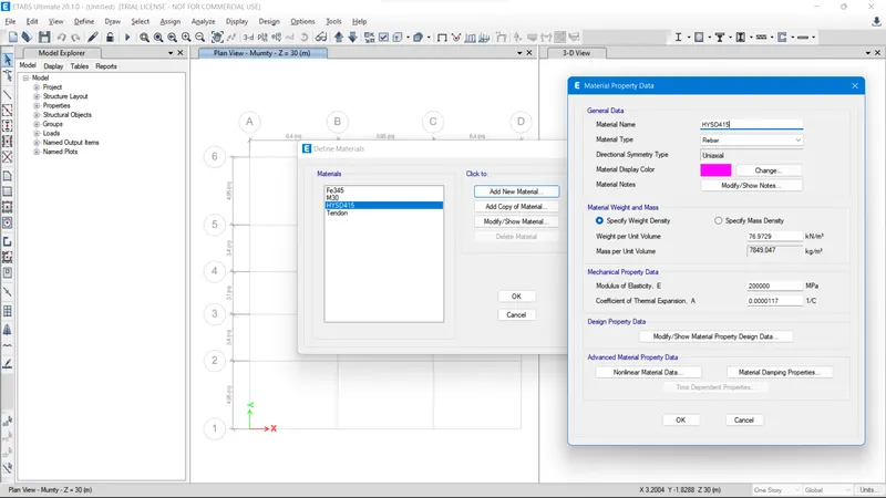
- Then Material Property Data Tab will open, here change the Material Name = HYSD415, Material Type = Rebar and click OK.
- Material property for Longitudinal Rebar also be defined.
- For that the same procedure should be followed such as click Define < Material Properties then the Define Materials Tab will be opened.
- In opened tab Click Add New material and select Region = India, Material Type = Rebar, Standard = Indian, Grade = HYSD Grade 550 and click OK.
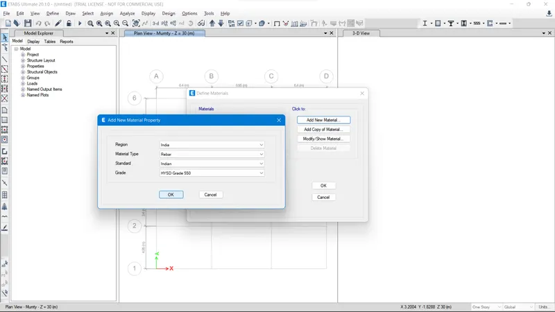
- Then Material Property Data Tab will open, here change the Material Name = HYSD550, Material Type = Rebar and click OK.
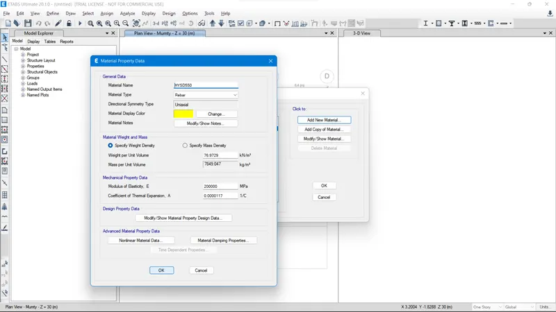
- Followed by the Frame sections for beams, columns has to be defined.
- For that click and select Define < Section properties < Frame sections.
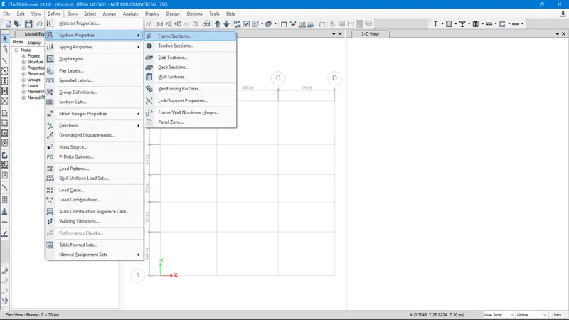
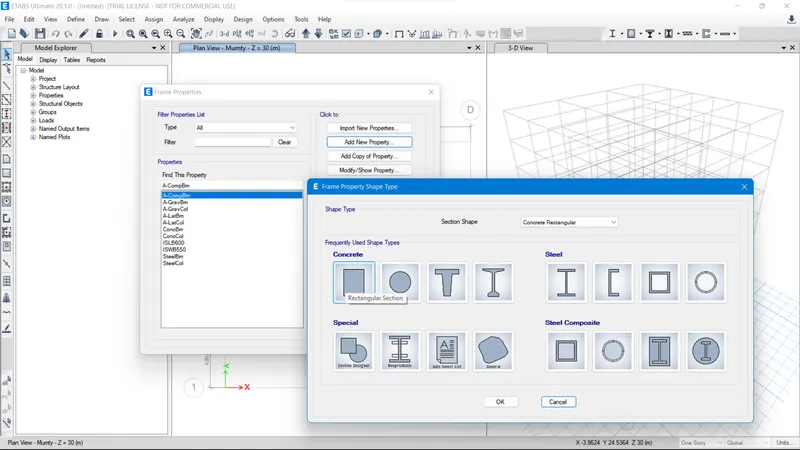
- Then the Frame Properties Tab will open, here click Add New Property.
- After clicking, Frame Property shape type Tab will open.
- From there select Rectangular Section under the concrete and click OK.
- Then the Frame Section Property Data Tab will open, First we should create a Beam Frame section Property.
- Here Change the Property Name = B400x500, Material = M30, Depth = 500mm, Width = 400mm.
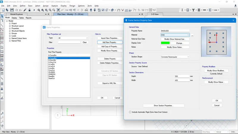
- To make the created Frame Section as Beam section Click Modify/Show Modifiers.
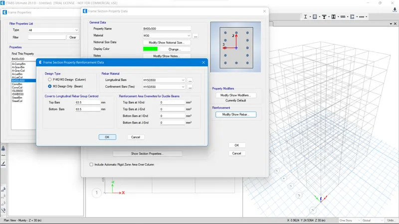
- Then the Frame section Property Reinforcement Data Tab will open, here we should change the Design Type.
- For that Select M2 Design Only (Beam) > Design Type, Longitudinal Bars = HYSD550, Confinement Bars (Ties) = HYSD550 and click OK.
- Likewise for Columns Sections from Frame Properties Tab click Add New Property.
- After clicking, Frame Property shape type Tab will open.
- From there select Rectangular Section under the concrete and click OK.
- Then the Frame Section Property Data Tab will open, First we should create a Column Frame section Property.
- Here Change the Property Name = C450x600, Material = M30, Depth = 600mm, Width = 450mm.
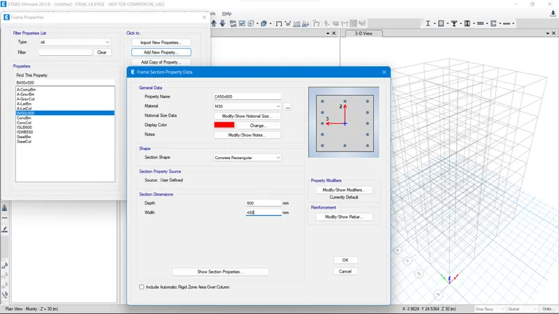
- To make the created Frame Section as Column section Click Modify/Show Modifiers.
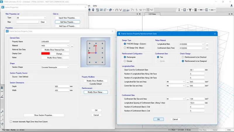
- Then the Frame section Property Reinforcement Data Tab will open, here we should change the Design Type.
- For that Select P-M2-M3 Design (Column) > Design Type, Longitudinal Bars = HYSD550, Confinement Bars (Ties) = HYSD550 and click OK.
- Likewise the Slab sections for Slab has to be defined.
- For that click and select Define < Section properties < Slab sections.
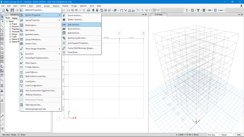
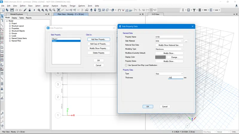
- Then Slab Properties Tab will open, here click Add New Property.
- After clicking, Slab property Data Tab will open here change the General Data appropriately.
- And make Property Name = S150, Slab Material = M30, Thickness = 150mm and click OK.
- Atlast the Wall sections for Shear wall has to be defined.
- For that click and select Define < Section properties < Wall sections.
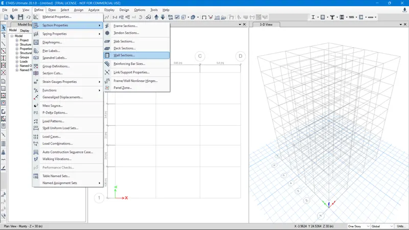
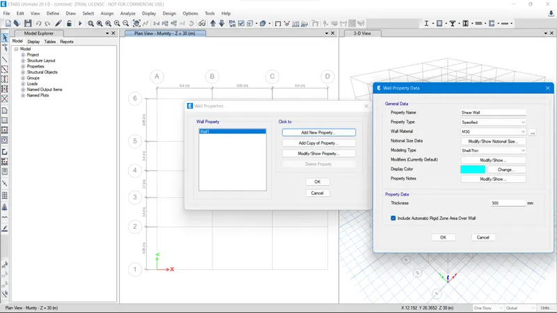
- Then Wall Properties Tab will open, here click Add New Property.
- After clicking, Wall property Data Tab will open here change the General Data appropriately.
- And make Property Name = Shear Wall, Wall Material = M30, Modelling Type = Shell-Thin, Thickness = 300mm and click OK.
- NOTE : Before clicking OK, we should make sure whether the Check box (Include Automatic Rigid Zone Area Over Wall) is selected.
- Now we can start Draw the created Sections all over the Grids.
- To create Beams, Select the Tool named Quick Draw Beams/Columns (Plan,Elev,3D) at the left corner of the workspace Toolbar menu.
- And select the created Beam Size B400x500 in the Properties of Object Tab < Property = B400x500.
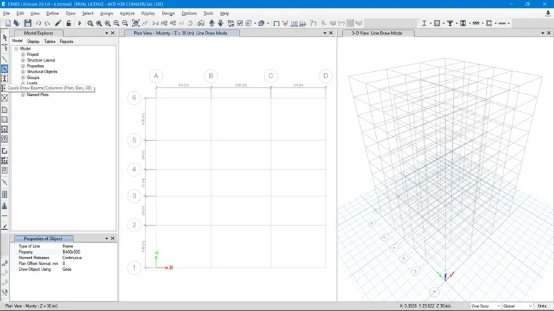
- Before assigning the Beams all over the grids of the Plan, we should make sure the beams should be provided to all stories.
- For that first click and select Set Plan View and the Select Plan View Tab will open.
- In the opened Tab, Select Story 1 and click Ok.
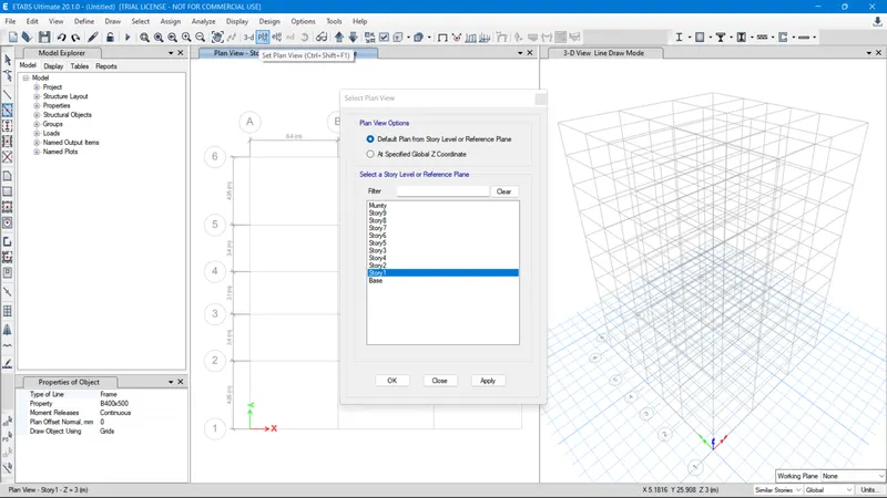
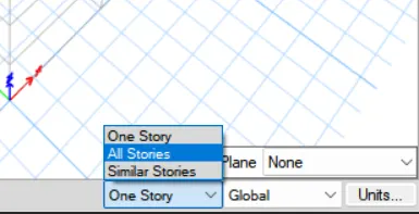
- Then we have to be make sure whether All Stories option is enables to assign the beams to all stories.
- Then we should click over the grid lines to assign the Beams.
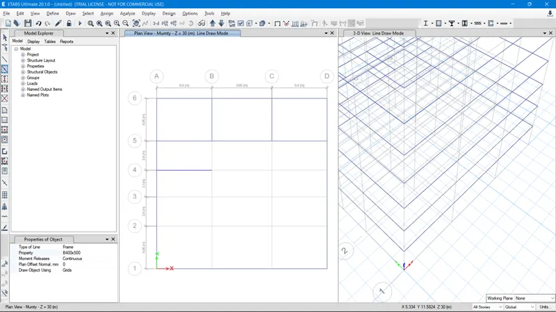
- After assigning the Beams all around the created model grids, the Columns should be assigned at the intersections of the assigned Beams.
- For that Select the Tool named Quick Draw Columns (Plan,3D) at the left corner of the workspace Toolbar menu.
- And select the created Column Size C450x600 in the Properties of Object Tab < Property = C450x600.
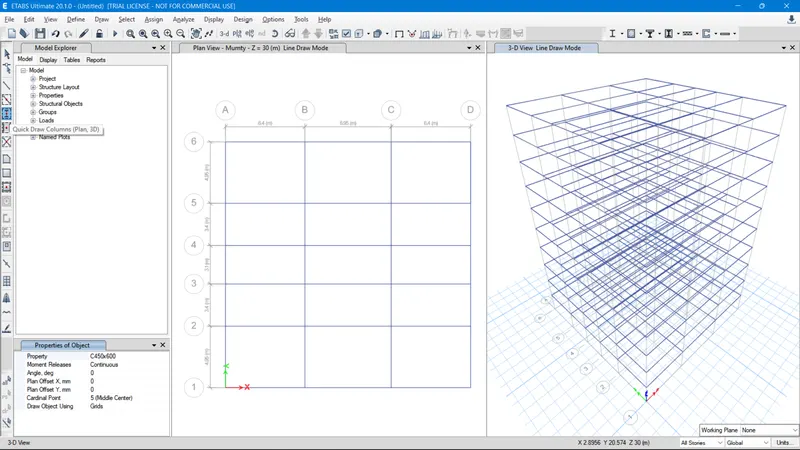
- Then we should click and assign the Columns at the intersections of all beams.
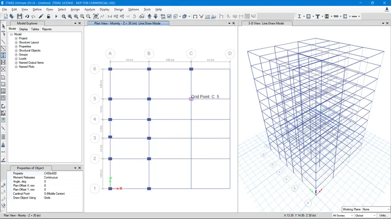
- After assigning all columns, we can see all the Column Orientations are in X direction.
- But some of the columns are needs to be in Y direction as appropriate.
- For that click and select the columns that needs to changed in its into Orientation.
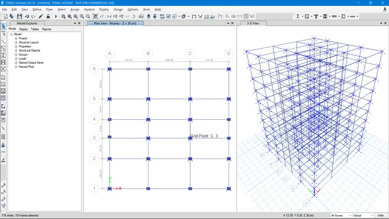
- Then click and select Assign < Frame < Local Axes to open Frame Assignment - Local Axes Tab.
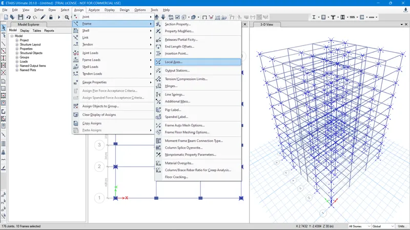
- From the opened Tab, make Rotate by angle = 90 degree > General Orientation > Define Orientation and click OK.
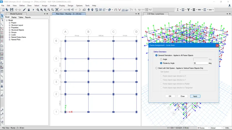
- Here we can see that the selected columns are rotated 90 degree from its Orientation from X to Y direction.
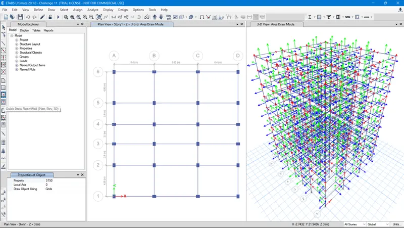
- Followed by beams and columns, the Slabs at the floor level should be assigned.
- For that click and select Set Plan view then we can see Select Plan View Tab will be opened.
- In the opened Tab select Story 1 and click Apply to view the Story 1 view plan.
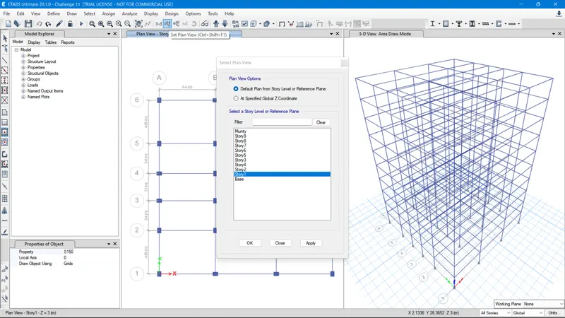
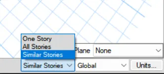
- Then we have to make sure whether Similar Stories option is enabled to assign the beams to all the simillar stories of story 1.
- By making the stories to Similar, we can ignore Slabs apply at the Base level.
- Then the Slabs should be assigned inbetween the assigned Beams and columns.
- For that Select the Tool named Quick Draw Floors (Plan,3D) at the left corner of the workspace Toolbar menu.
- And select the created Slab Thickness = 150mm in the Properties of Object Tab < Property = S150.
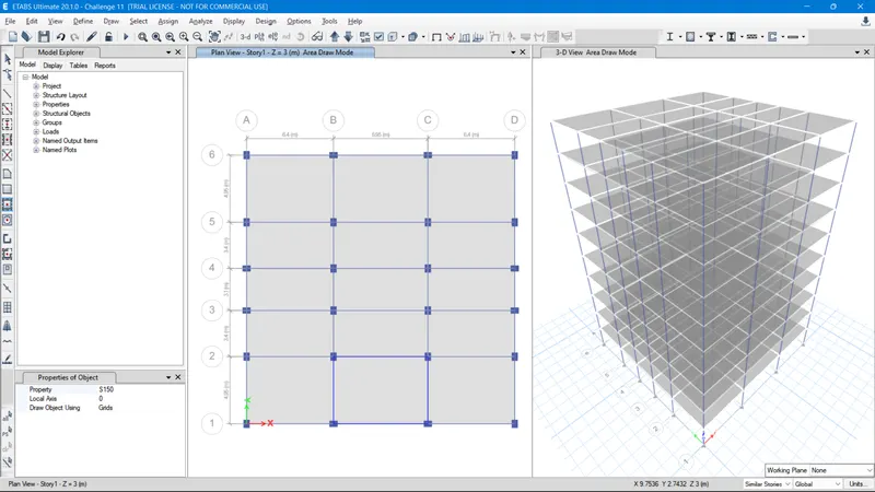
- Below we can see the building model with assigned Beams, Columns and Slabs.
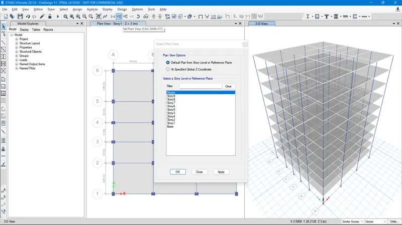
- Then again click Set plan View and from Select Plan view Tab select Mumty level and click Apply to open Mumty level Plan view.
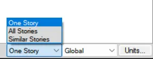
- Here we have to make sure whether One Stories option is enabled to edit Slabs at Mumty level.
- By making the editable stories to One Stories at Mumty level, we can ignore Slabs edited other than Mumty level.
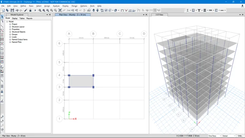
- Here Delete all the other Slabs assigned at Mumty level and leave the slab above the area for Steps from Story1 to Mumty.
- Now, we should assign the Shear Walls at the approprite location of the building model.
- To assign shear walls upto the Roof level, Click Set plan view to open Select plan view tab and select Roof Level and click Apply.
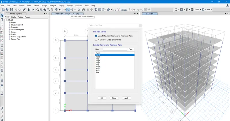
- Then we have to Delete a part of beams at the place where we want to assign Shear walls.
- For that we should Replicate the beams upto the size of the Shear wall to break the intersection points of the replicated beams.
- So click and select beam which has to replicated at X or Y direction, then select Edit < Replicate.
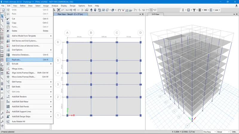
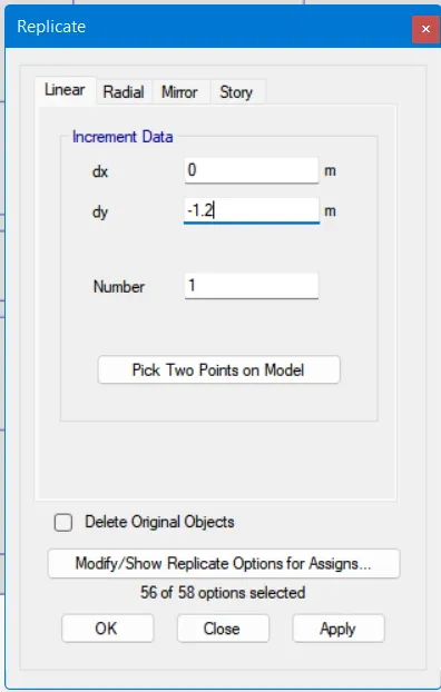
- After selecting the Replicate Tab will open, type the recommended distance where the beam should be replicated and click Apply.
- Here we have typed dy = -1.2 from Linear < Increment Data < dy = 0m, dy = -1.2m .
- After replicating all the required beams, select all the replicated beams and other intersecting beams.
- Then click and select Edit < Edit Frames < Divide Frames to open Divide selected Frames Tab.
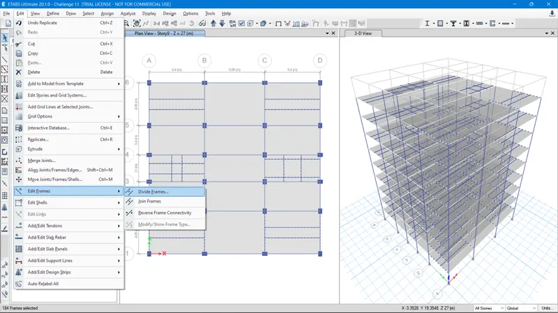
- In opened Tab select Break at intersections with selected frames and joints.
- And click Apply to break the intersection points of all the Beams replicated and selected.
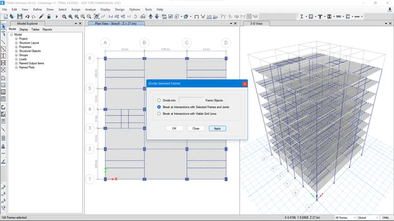
- Then we can Delete the beams at the break points to assign the Shear walls.
- Now click and select Draw Wall (plan) tool at the left corner of the workspace toolbar menu.
- Then select the created Shear wall from the Properties of Object tab < Property = Shear wall.
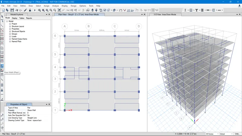
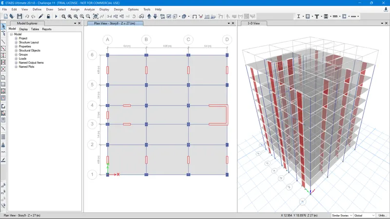
- After selecting the appropriate Shear wall property, try assigning the Shear walls at the allocated location.
- Below we can see the Shear walls assigned at the appropriate locations symmetrically.
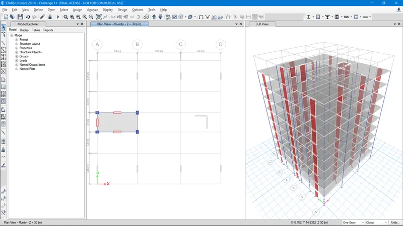
- Now we should assign the created Shear walls around the Staircase area mumty level.
- For that Set the Plan view to mumty level and make the stories to One story.
- After that select the deleted beam area to assign the shear wall at the Mumty level.
- Then we should make Restraints of the Base Level as Fixed from the pinned (default) .
- For that first set the Plan view to Base level from Set Plan view < Select Plan View < Base and click Apply.
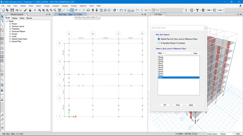
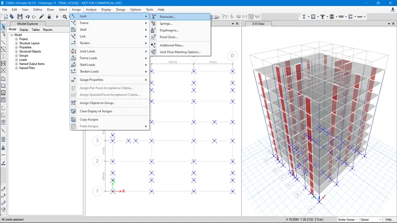
- After setting the Plan view to Base, click and select Assign < Joint < Restraints .
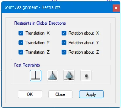
- Then the Joint Assignment - Restraints Tab will open, here the Fixed joint has to be selected.
- For that select First icon below the Fast Restraints and click Apply.
- After assigning the Fixed Restraints at the base, we should Define the Load Patterns.
- For that click and select Define < Load patterns to open Define Load Pattern Tab.
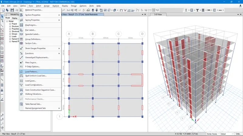
From opened Tab, Add new loads as Dead (Default) = Dead, Live = Live, Brickwall = Super Dead, Finishes = Super Dead and click OK.
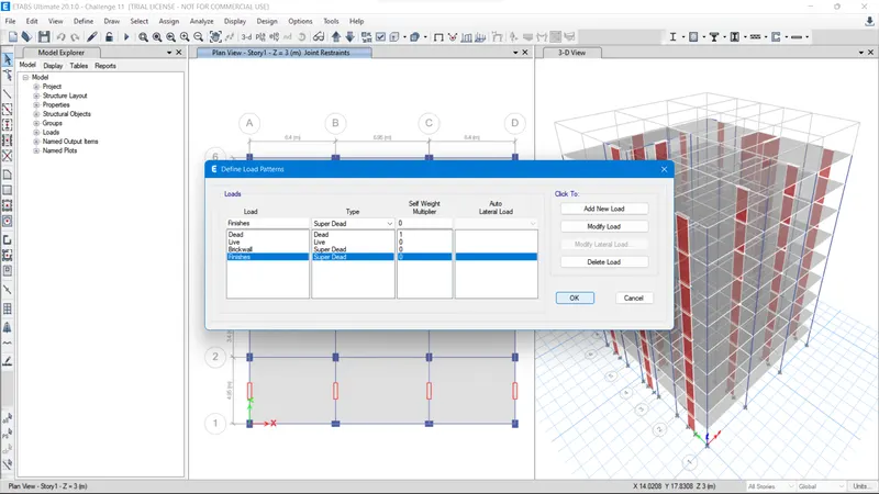
- Now the Brick Wall Loads (Super Dead) should be applied over the Frames as Distributed Load.
- For that first set the Plan view at the Story 1 by selecting Set Plan View < Select plan View < Story1 and click Apply.
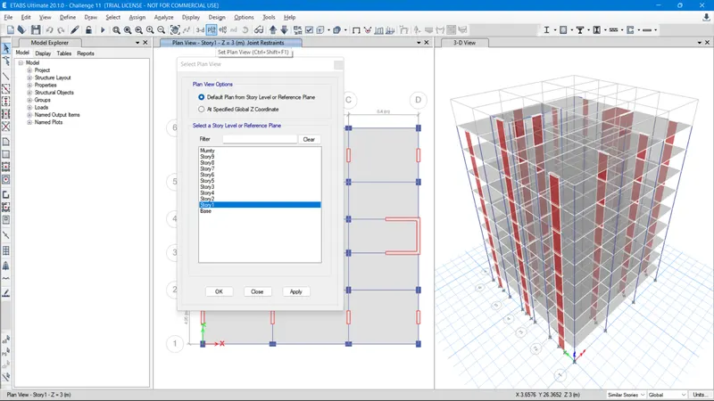
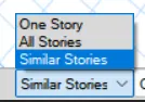
- Then we have to make sure whether Similar Stories option is enabled to assign the Distributed Loads to all the simillar stories of story 1.
- By making the stories to Similar, we can ignore the Load applying to the frames not supporting wall loads such as Roof and Mumty level.
- Now Select all the Beam Frames except the shear walls of the plan to assign the Loads over the Beams.
- To apply the load, Select Assign < Frame Loads < Distributed to open the Frame Load Assignment - Distributed Tab.
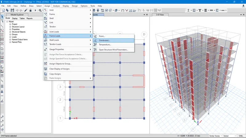
- From the opened Tab, Select Load Pattern Name = Brick Wall, and Uniform Load = 5 (Default) and click OK.
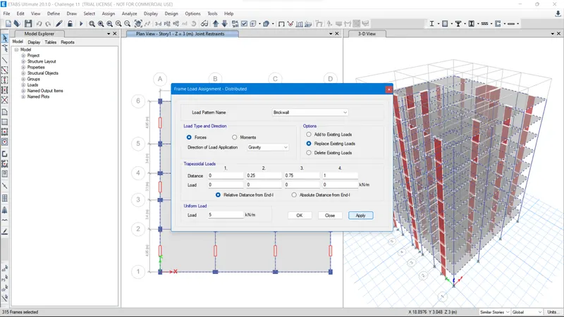
- After assigning the Distributed load over the Beam frames, we can see the applied load from one story separately.
- To view it, click and select the tool named Perspective Toggle at the Top of the workspace Toolbar menu.
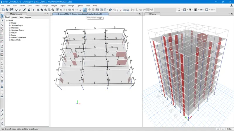
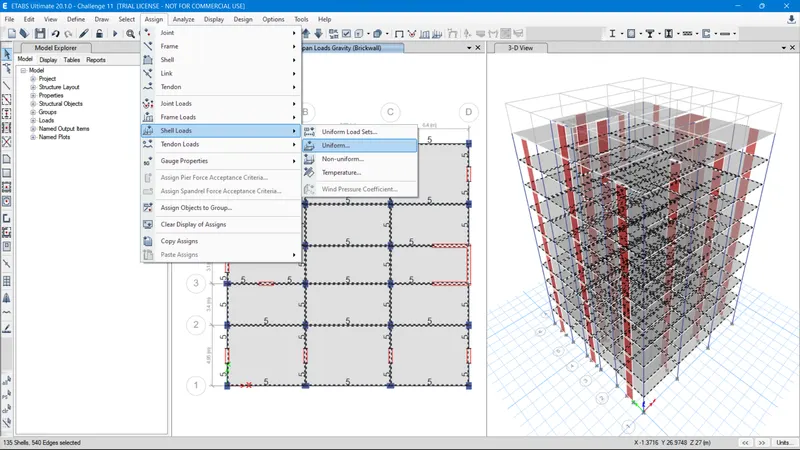
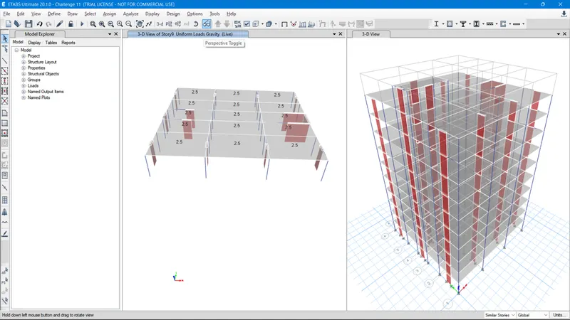
- Then the Live Load as Uniform load should be applied over the Slabs of all similar stories with slabs assigned.
- For that select all the Slabs, then Click and Select Assign < Shell Loads < Uniform to open Shell Load Assignment - Uniform Tab.
- From opened Tab, make Load Pattern Name = Live, Load = `2.5 kN/m^2` and click Apply.
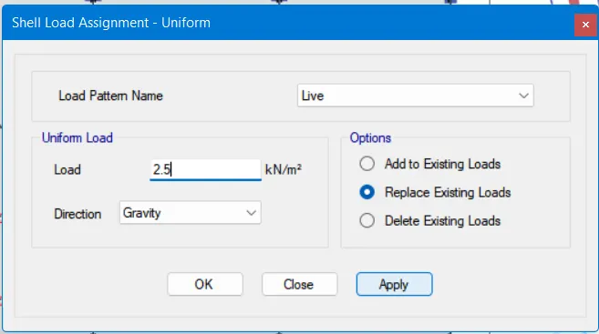
- After assigning the Uniform load over the Slabs, we can see the applied load from one story separately.
- To view it, click and select the tool named Perspective Toggle at the Top of the workspace Toolbar menu.
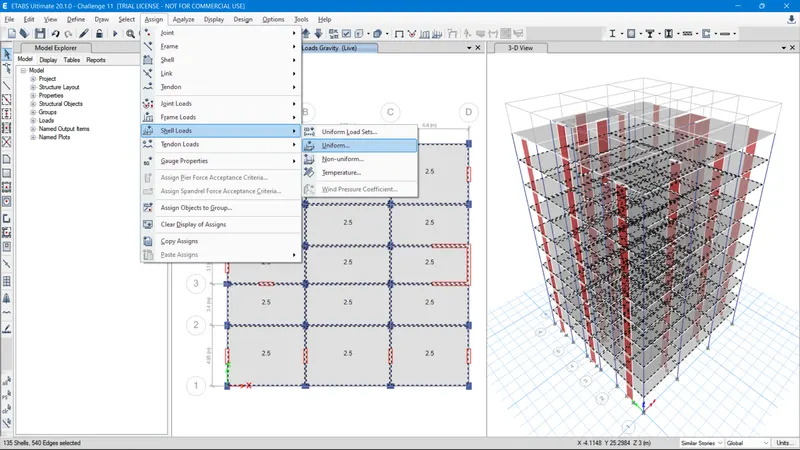
- Likewise the Floor Finishes load as Uniform load should be applied over the Slabs of all similar stories with slabs assigned.
- For that select all the Slabs, then Click and Select Assign < Shell Loads < Uniform to open Shell Load Assignment - Uniform Tab.
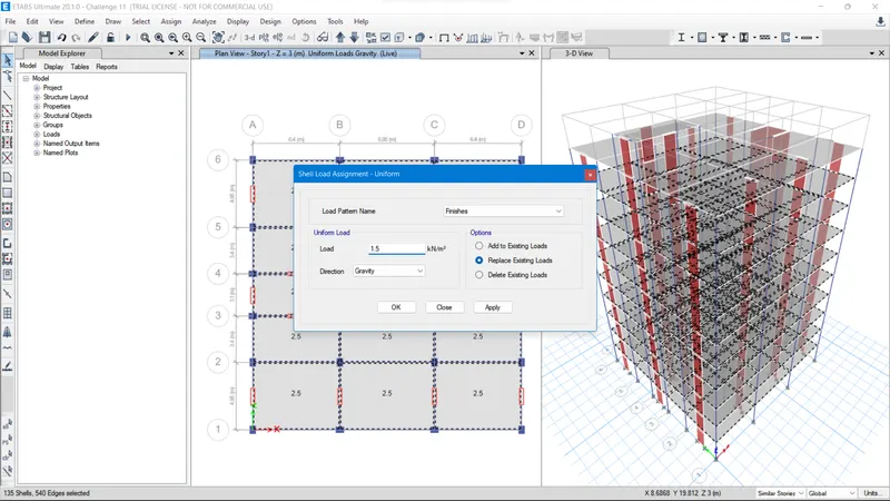
- From opened Tab, make Load Pattern Name = Finishes, Load = `1.5 kN/m^2` and click Apply.
- Atlast the Over Head Tank Load of 20 kN (`1kN/m^2`) should be applied separately at Mumty level.
- For that Set the Plan view at the Mumty level by clicking Set Plan view < Select Plan View < Mumty and click Apply.
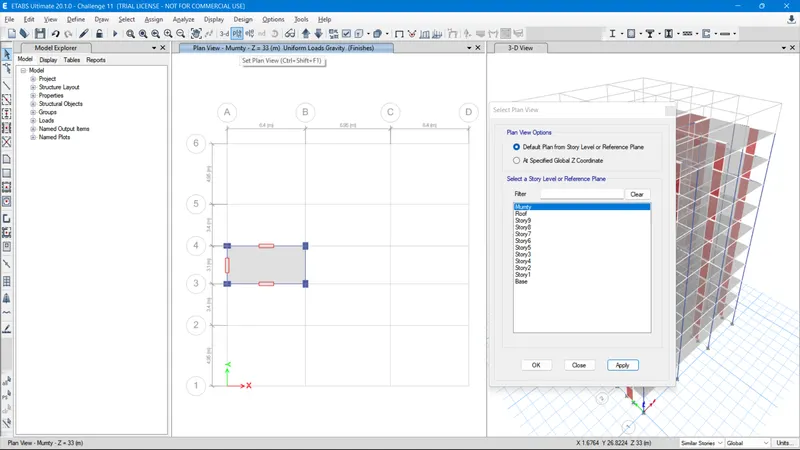
- Then select Assign < Shell Loads < Uniform to open the Shell Load Assignment - Uniform Tab.
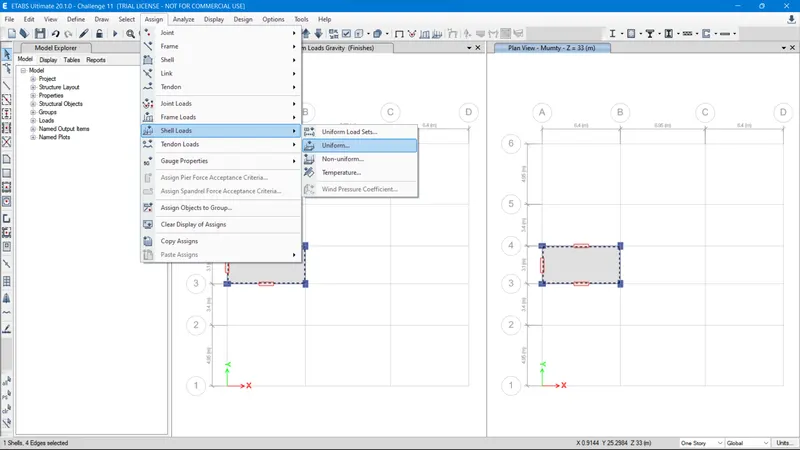
- From opened Tab, make Load Pattern Name = Live, Load = `1 kN/m^2` and click Apply.
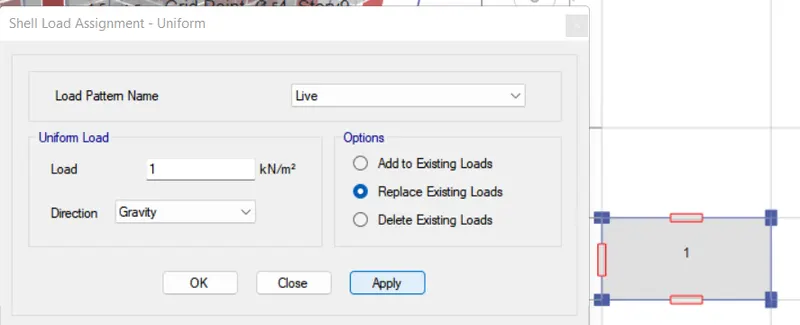
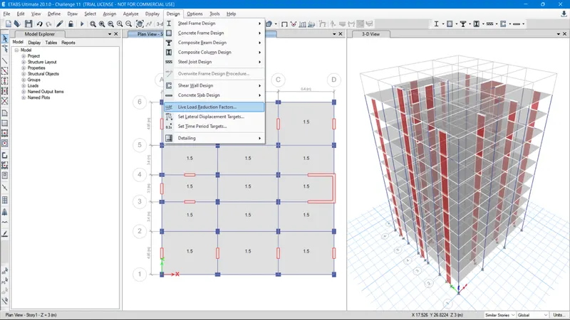
- Then the Live Load Reduction Factors should be Added for every Stories by reducing gradually from Story1 to Story9.
- For that click and select Design < Live Load Reduction Factors to open Live Load Reduction Factor Tab.
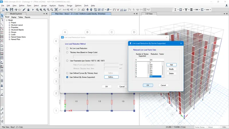
- From the opened Tab, select User Defined (By stories supported) and click Define.
- After click Define, Live Load Reduction By Stories Supported Tab will open.
- Here, we should add the add the all story names along with the Load Reduction value.
- It should be reducing gradually from 1 to 0.6 and not less than 0.6 and click OK.
- Then we should calculate the Ta (Approximate Natural Time period) value of the building in both X and Y direction.
- To get that refer IS-Part I-1893 2016, Clause 7.6.2 c) All other buildings `Ta = 0.09h/sqrtd`
Where,
h = Height of building.
d= Base dimension of the building at the plinth level along the considered direction of earthquake shaking, in m.
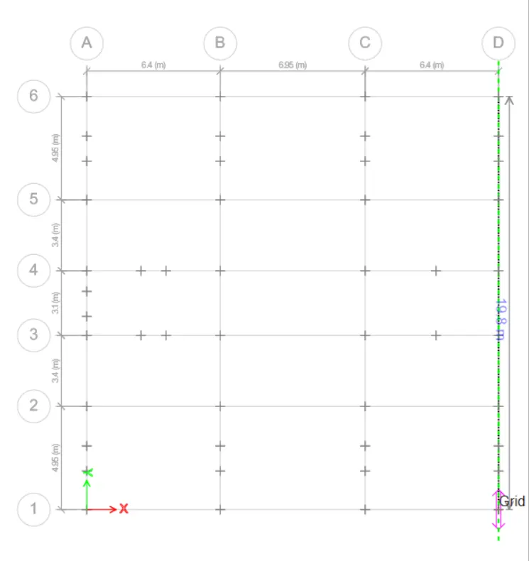
- To know the Base dimension (d) of the building select the Beam Drawing tool and try to measure the Base Dimension (d) value.
- Below the image we can see the Base Dimension (d) = 19.8m .
- Then to know the Height of the building (h), we should visit the Elevation height from the Story data Tab.
- For that click and select Edit < Edit Stories and Grid System to open Edit Stories and Grid System Data Tab.
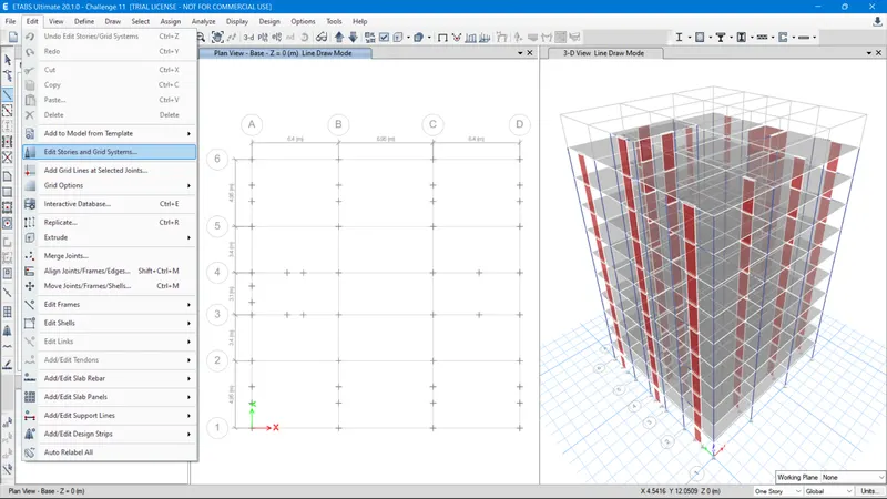
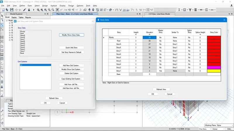
- After opening of the Tab, click the Modify/Show Story Data option to open the Story Data Tab.
- In the opened Story Data Tab, we can see the height of the building as Elevation m = 33m.
- Then we should find out the Time period the Earthquake in X direction by using the formula obtained from IS 1893-Part I-2016.
`Ta = 0.09h/sqrtd`
`Ta = 0.09 (33)/sqrt(19.8)`
Ta= 0.66
- Before that we should create Load Patterns for all Loads along with Seismic loads for all the directions of the building.
- The Earthquake Loads which needs to be added in Load Patterns are Eqx, Eqx-, Eqx+, Eqy, Eqy-, Eqy+.
- To Define the Load Patterns click and select Define < Load Patterns to open Define Load Pattern Tab.
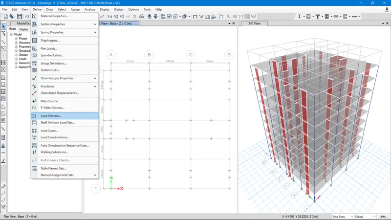
- From the Opened Tab, Add New Loads such as
- Dead Load (Default) = Dead, 1, None.
- Live Load = Live, 0, None.
- BrickWall = Super Dead, 0, None.
- Finishes = Super Dead, 0, None.
- Eqx = Seismic, 0, lS 1893 2016.
- Eqx- = Seismic, 0, lS 1893 2016.
- Eqx+ = Seismic, 0, lS 1893 2016.
- Eqy = Seismic, 0, lS 1893 2016.
- Eqy- = Seismic, 0, lS 1893 2016.
- Eqy+ = Seismic, 0, lS 1893 2016.
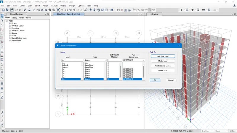
- Then We should change the Direction and Eccentricity for all the Earthquake loads created as per their directions of Seismic forces.
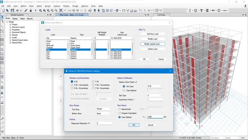
- First Select Seismic Load Eqx and click Modify/Lateral Load to open Indian IS 1893-2016 Seismic Loading Tab.
- From the opened tab, click the Check box of X Dir and unclick all the other check box below Direction and Eccentricity at let the other values as default.
- And click User Defined option below the Time Period, then Input the Calculated Time period Ta = 0.66 sec and click OK.
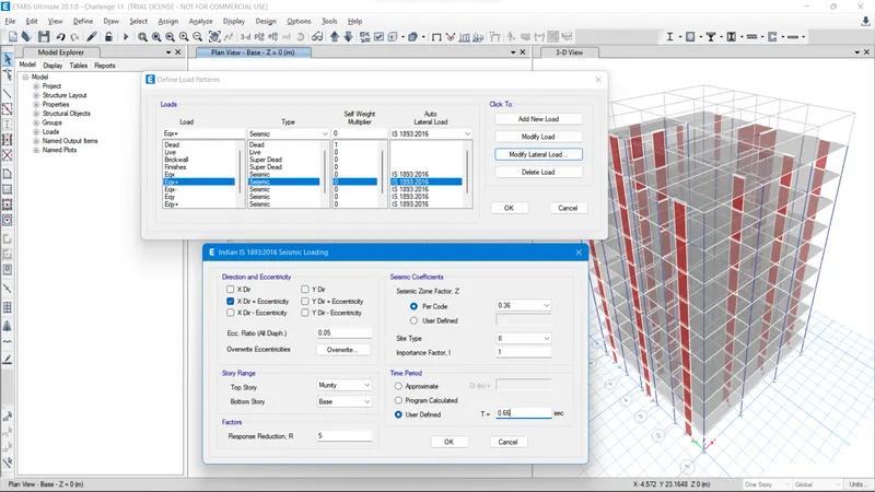
- Second Select Seismic Load Eqx+ and click Modify/Lateral Load to open Indian IS 1893-2016 Seismic Loading Tab.
- From the opened tab, click the Check box of X Dir + Eccentricity and unclick all the other check box below Direction and Eccentricity at let the other values as default.
- And click User Defined option below the Time Period, then Input the Calculated Time period Ta = 0.66 sec and click OK.
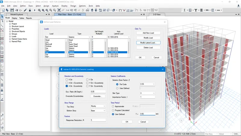
- Second Select Seismic Load Eqx- and click Modify/Lateral Load to open Indian IS 1893-2016 Seismic Loading Tab.
- From the opened tab, click the Check box of X Dir - Eccentricity and unclick all the other check box below Direction and Eccentricity at let the other values as default.
- And click User Defined option below the Time Period, then Input the Calculated Time period Ta = 0.66 sec and click OK.
- Second Select Seismic Load Eqy and click Modify/Lateral Load to open Indian IS 1893-2016 Seismic Loading Tab.
- From the opened tab, click the Check box of Y Dir and unclick all the other check box below Direction and Eccentricity at let the other values as default.
- And click User Defined option below the Time Period, then Input the Calculated Time period Ta = 0.66 sec and click OK.
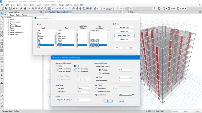
- Second Select Seismic Load Eqy+ and click Modify/Lateral Load to open Indian IS 1893-2016 Seismic Loading Tab.
- From the opened tab, click the Check box of Y Dir + Eccentricity and unclick all the other check box below Direction and Eccentricity at let the other values as default.
- And click User Defined option below the Time Period, then Input the Calculated Time period Ta = 0.66 sec and click OK.
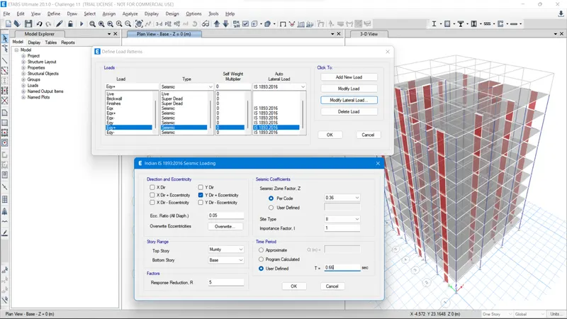
- Second Select Seismic Load Eqy- and click Modify/Lateral Load to open Indian IS 1893-2016 Seismic Loading Tab.
- From the opened tab, click the Check box of Y Dir - Eccentricity and unclick all the other check box below Direction and Eccentricity at let the other values as default.
- And click User Defined option below the Time Period, then Input the Calculated Time period Ta = 0.66 sec and click OK.
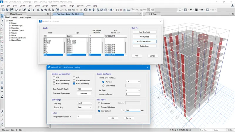
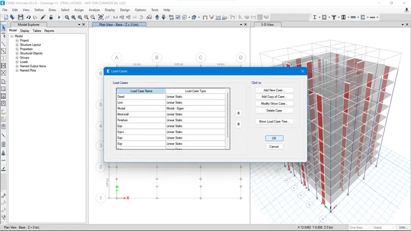
- Then we should check the Load cases whether the created Loads are added in the model or not.
- To open it click and select Define < Load Cases to open a Load Cases Tab.
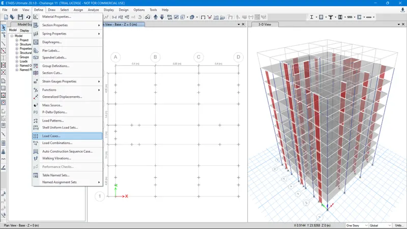
- From the opened Load Cases Tab, check all the created loads are defined and click OK.
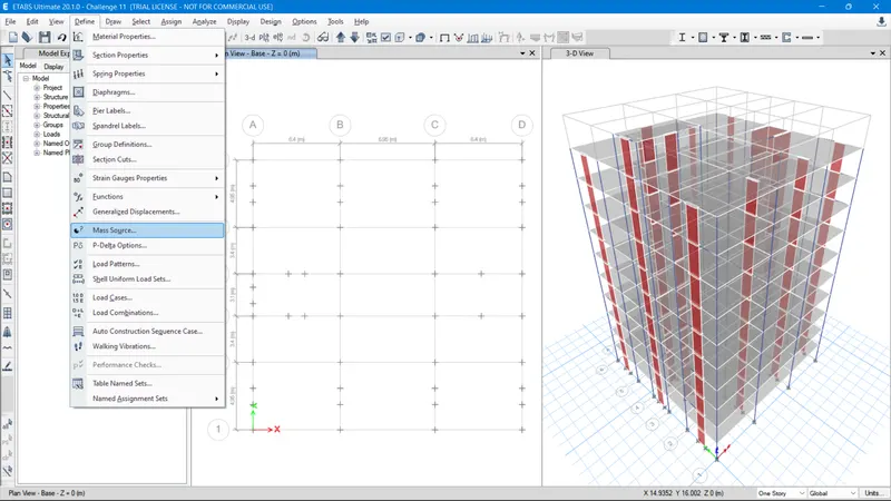
- Then the Loads in Mass Source should be added.
- For that click and Select Define < Mass Source to open the Mass Source Tab.
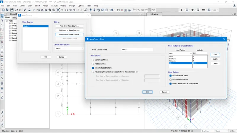
- In the opened Tab, Click Modify/Show Mass Source option to open The Mass Source Data Tab.
- Then from the opened Mass Source Data Tab, Click the check box of Specified Load Patterns below the Mass Source and Unclick all the other CheckBoxes.
- Followed by Add Load patterns and Multipliers as Dead = 1, BrickWall = 1, Finishes = 1, Live = 0.25 and click OK.
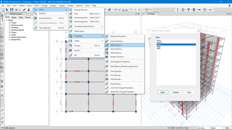
- Then we should assign the Center of gravity (DIAPHRAGM) to all the Floor/Slab.
- For that Select all the Drawn Slabs by clicking and selecting Select < select < properties < Slab Sections < S150 and click Select to select all the assigned Slabs.
- Then to assign Diaphragm click and select Assign < Shell < Diaphragm to open a Shell Assignment - Diaphragms Tab.
- After opening of the Tab, Select D1 and click Apply to assign the Diaphram to all the slabs.
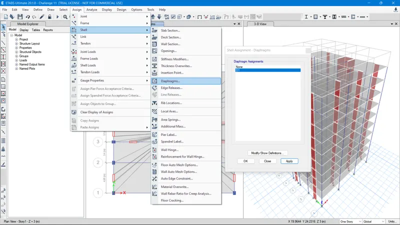
- After Assigning the Diaphragm, we should Assign a Pier Lables to all the Shear Wall before Running analysis.
- For that Click and Select Assign < Shell < Pier Label to open a Shell Assignment - Pier Label Tab.
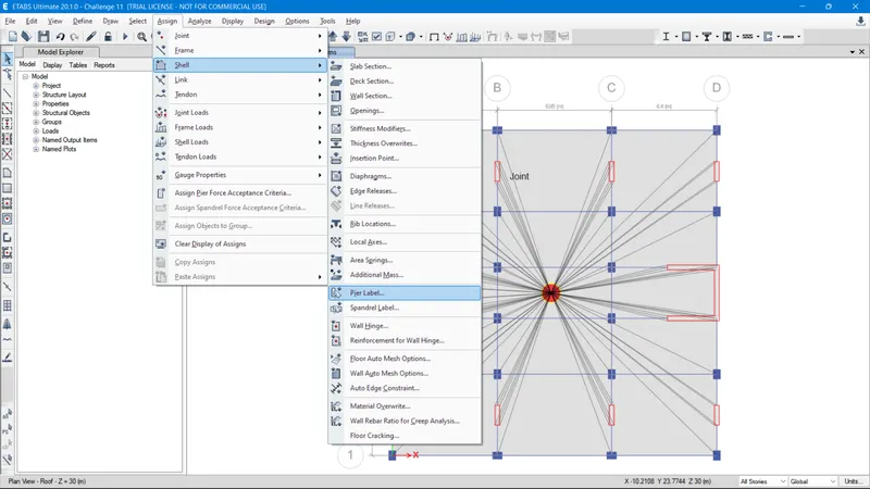
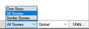
- Before Start assigning the Pier Labels, we should make sure whether Editable Stories are changed as All Stories.
- After opening of the Shell Assignment - Pier Label Tab, click Modify/Show Definitions and Add number of Labels as equal as Shear Walls created.
- Then click and select the Shear Walls one by one to assign the Suitable Pier Lable to them by clicking Apply.
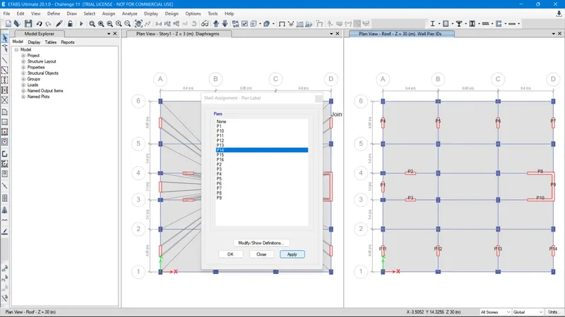
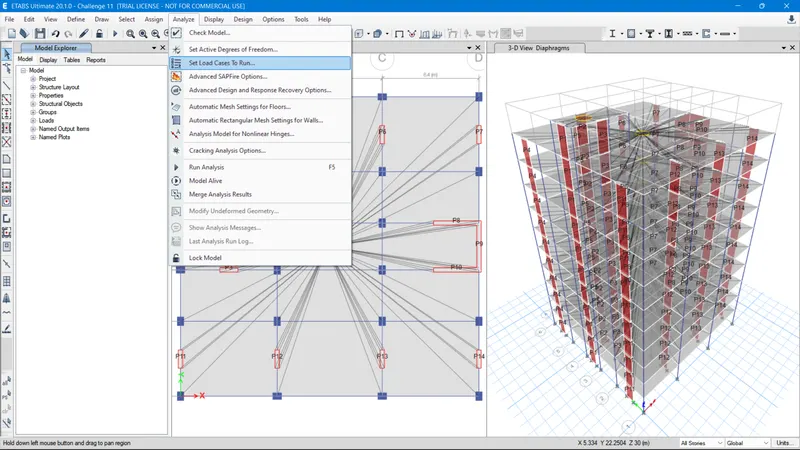
- Also we should make sure to Set Load Cases to Run before Start to Run Analysis.
- For that Click and Select Analyse < Set Load Cases to Run to open Set Load Cases to Run Tab.
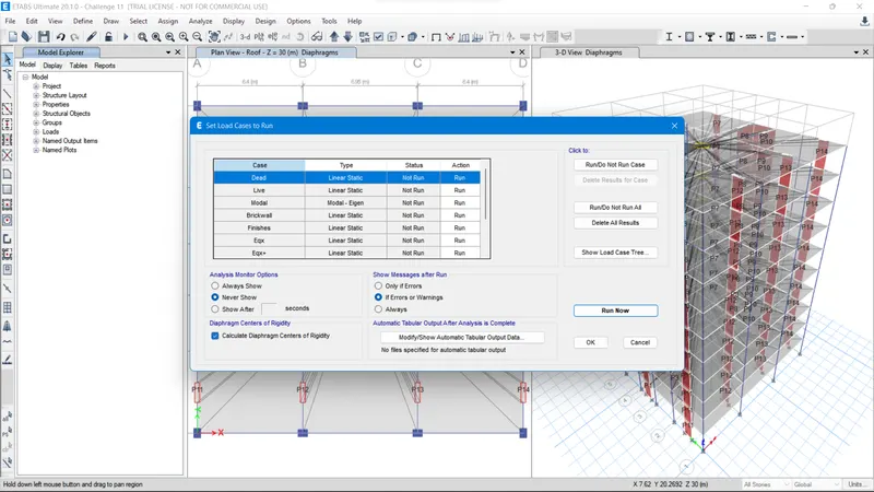
- After opening of the Tab, check whether the Action = Run for All Cases.
- And make sure to click the check box of Calculate Diaphragm Centers of Rigidity and click OK.
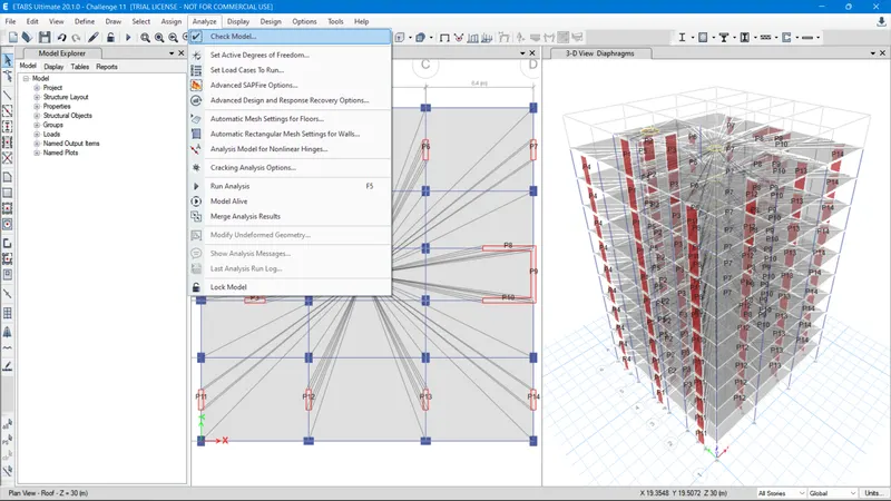
- Then we can Check whether the created model has generated any Warning Messages.
- To check that Click and Select Analyze < Check Model to open a Warning Tab.
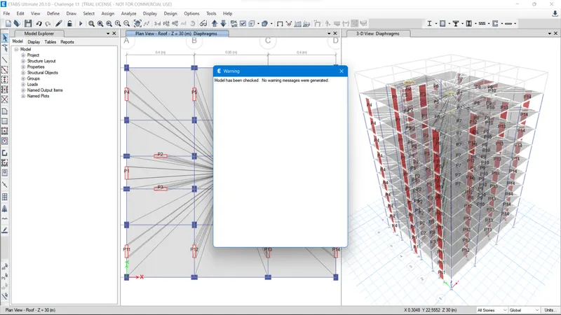
- From the opened Warning Tab, we can see that the Model has been checked. No warning messages were generated.
- So the created model were ready to Run the analysis.
- Before Start Running the Analysis, the Response spectrum should be defined as per IS Code 1893 2016.
- For that Click and Select Define < Functions < Response Spectrum to open Define Response Spectrum Functions Tab.
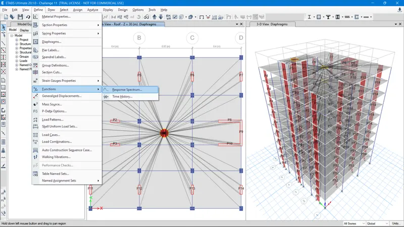
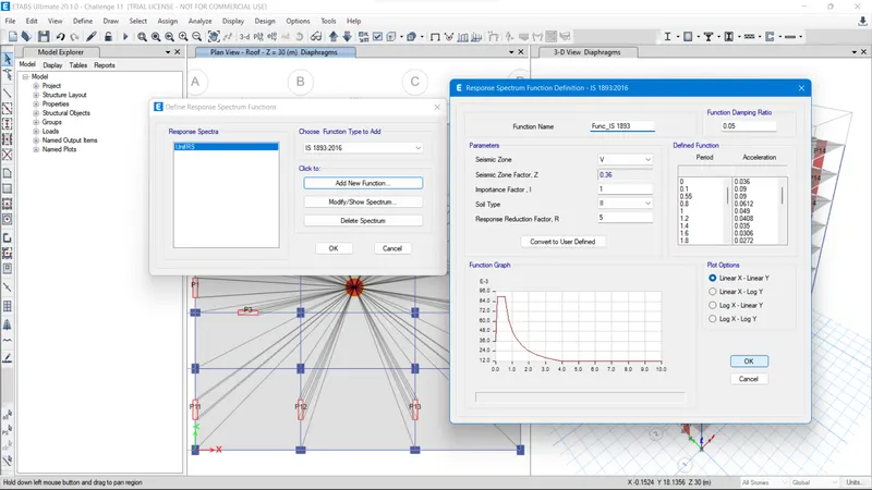
- From the opened Tab, Select IS 1893 2016 below the Choose function Type to Add and click OK.
- Then the Response Spectrum Function Definition - IS 1893 2016 Tab will be open, here make the appropriate Parameters.
- Here change Function Name = Func_IS 1893, Parameters < Seismic Zone = V, Seismic Zone Factor Z = 0.36, Importance Factor I = 1, Soil Type = II, Response Reduction Factor R = 5 and click OK.
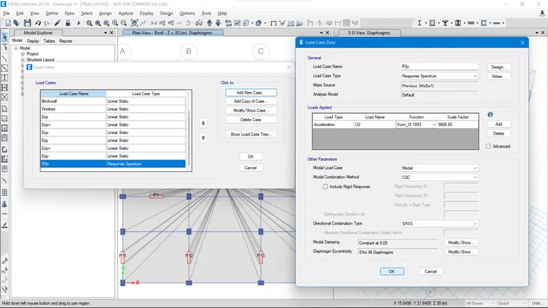
- Followed by we should Add New Case Load for the Response Spectrum Load in both X and Y directions in Load Case Data.
- For that click and select Define < Load Cases to open Load Cases Tab.
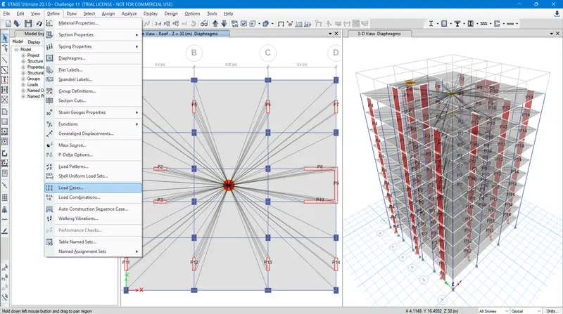
- From the opened Tab, click and Select Add New Case to open Load Case Data Tab to Apply Load for Response Spectrum in X direction.
- In the opened Load Case Data Tab, Change Load Case Name = RSx, Load Case Type = Response Spectrum.
- And in Load Applied < Load Type = Acceleration, Load Name = U1, Function = Func_1893, Scale Factor as Default and click OK.
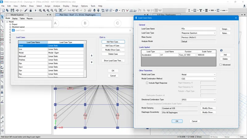
- Likewise to Apply Load for Response Spectrum in Y direction click and Select Add New Case to open Load Case Data Tab
- Then in the opened Load Case Data Tab, Change Load Case Name = RSy, Load Case Type = Response Spectrum.
- And in Load Applied < Load Type = Acceleration, Load Name = U2, Function = Func_1893, Scale Factor as Default and click OK.
- Atlast we should Define the Load combinations for the Added Loads.
- For that click and select Define < Load combination to open Load combinations Tab.
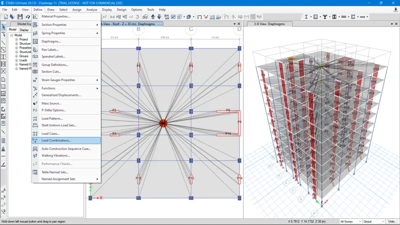
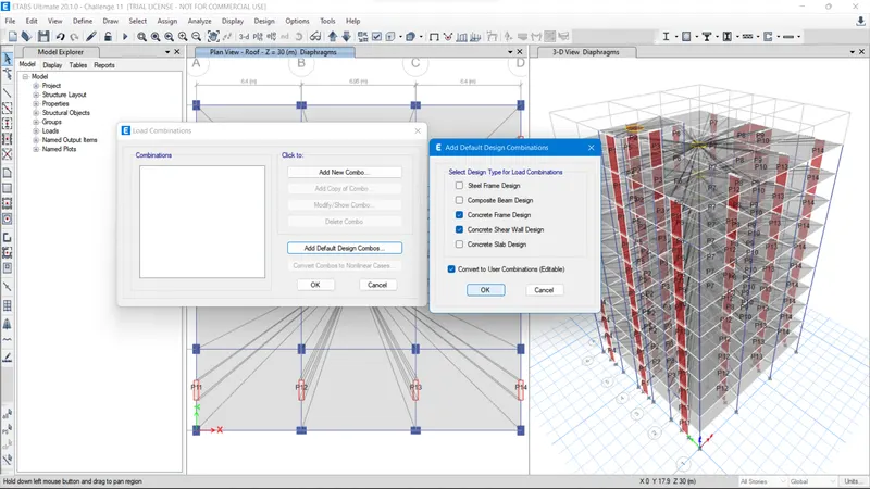
- From the opened Tab, Click Add Default Design Combos to open Add Default Design Combinations Tab.
- Here in opened Tab, click the Check Boxes of Concrete Frame Design and Concrete Shear wall Design and click OK.
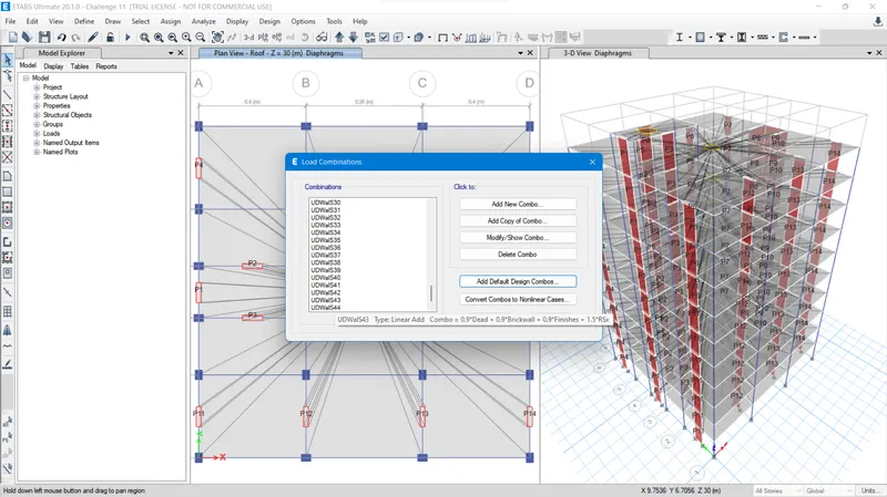
- After clickin OK, we can see the Load Combinations of All loads are combined and added.
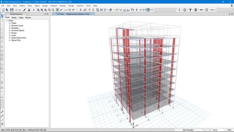
- Now we can Run Analysis of the Model created to see the Deformed Shapes and Base Reaction by the Loads Applied.
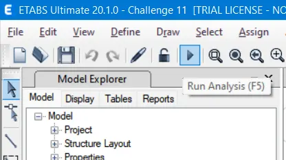
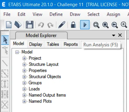
- To Run the Analysis, Click the Tool present at the Toolbar menu at the Top of the workspace names Run Analysis (F5).
- Here, we can see the Deformed shapes of the building model after Running the Analysis.
- Now we can see the Base Reaction values of the Building Model from the Analysis Result Table.
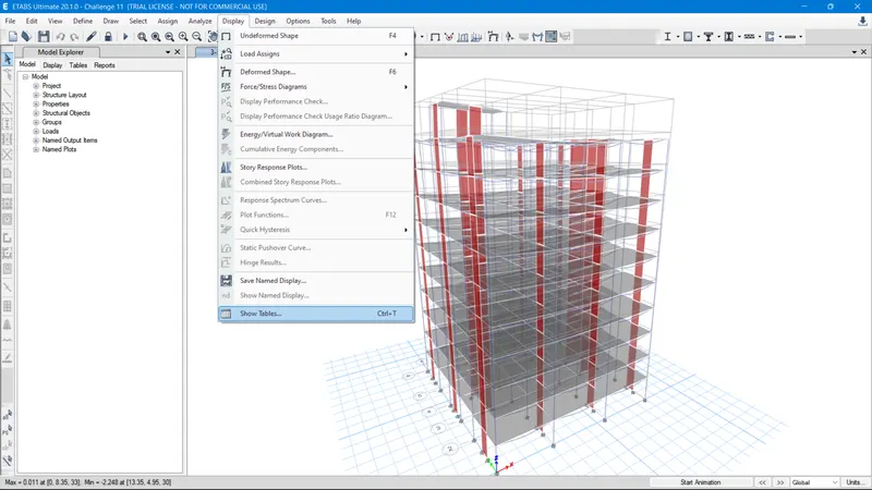
- To open the Analysis Result Table, Click and Select Display < Show Table to open Choose Tables for Display Tab.
- After opening of the Tab, Click and Select Analysis Result < Structure Output < Base Response < Table Base Reactions.
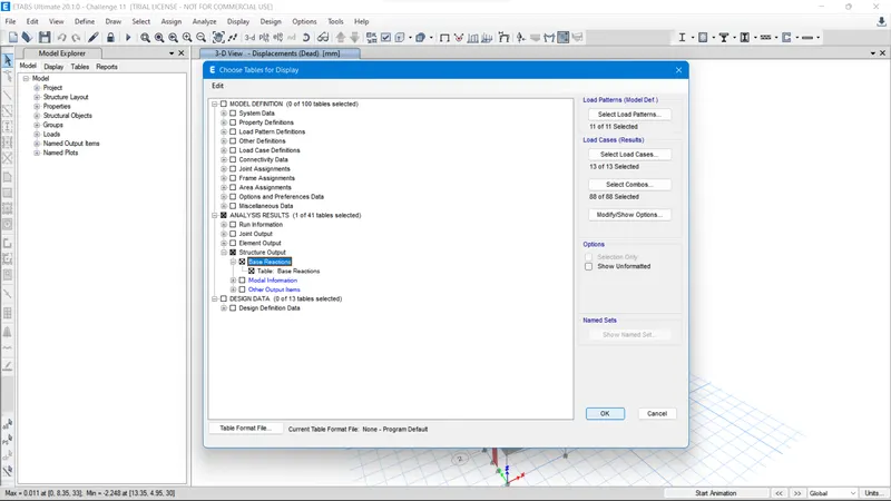
- From the opened Tab, we can see Result of all the Base Reaction of the building model.
- Here we can see that for Eqx, Eqx+, Eqx- the FX = 3559.4142 kN and for Eqy, Eqy+, Eqy- the FY = 3559.4142 kN.
- But the values for RSx and RSy did not has the values near the values of Earthquake forces in all directions.
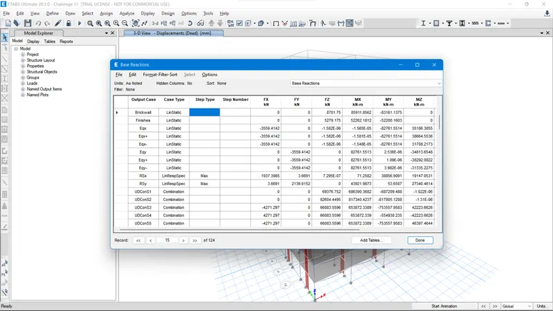
- To make the Response spectrum forces as equal to the Earthquake forces we should change the appropriate Scale factor for both RSx and RSy.
- For that Click and Select Define < Load Cases to open Load cases Tab .
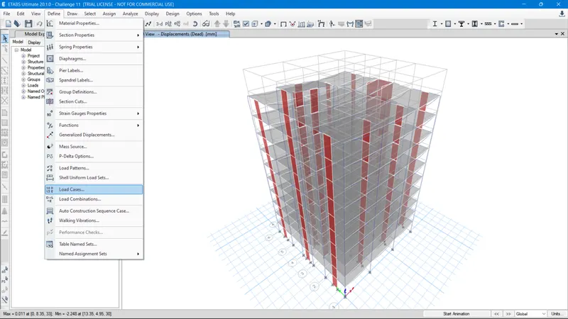
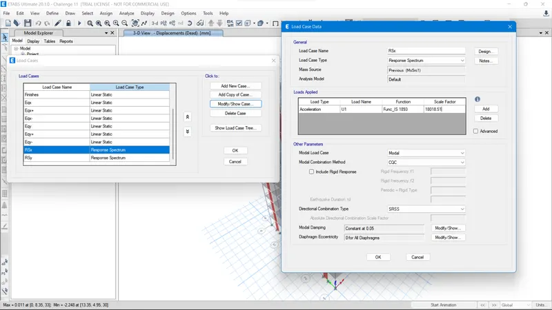
- From the opened Tab, click RSx and Select Modify/Show Case to open Load case Data.
- In opened Tab, Edit the Scale factor we calculated below.
RSx = 1937
Eqx = 3559
SFx2 = Eqx/RSx (SFx1)
SFx2 = 3559/1937 (9806.65)
SFx2 = (1.837) 9806.65
SFx2 = 18018.51
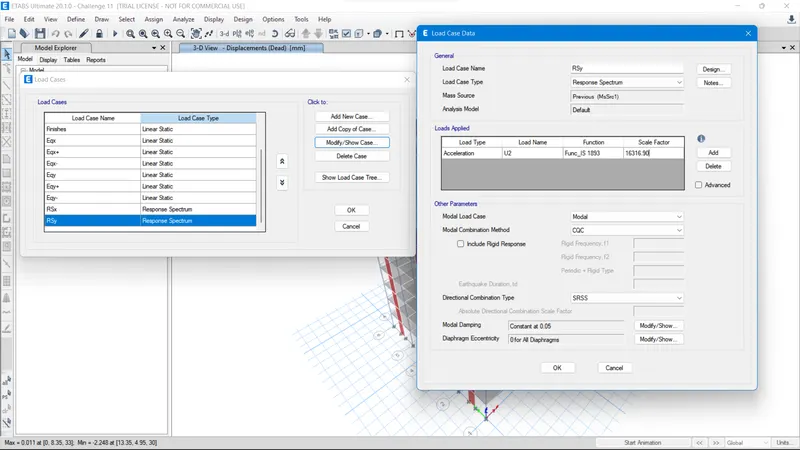
- Likewise for RSy, click RSy and Select Modify/Show Case to open Load case Data.
- In opened Tab, Edit the Scale factor we calculated below.
RSy = 2139
Eqy = 3559
SFy2 = Eqy/RSy (SFy1)
SFy2 = 3559/2139 (9806.65)
SFy2 = (1.663) 9806.65
SFy2 = 16316.90
- Then again click and Run the Analysis of the Building model with edited Scale Factor.
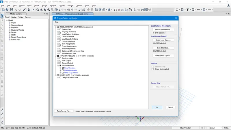
- After the Analysis of the model we can see the Table of the Analysed Result .
- To open the Table click and Select Display < Show Tables.

- Then the Choose Tables for Display Tab will open, there click and select Analysis Results < Structural Output < Base Reaction.
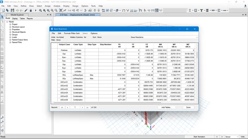
- Then the Base Reaction Tab will open, here we can see the Response spectrum Load values are almost equal to the Earthquake Load Values in Base Reaction.
- Now we can see that the structural model we have designed and analysed meets structural code requirements without compromising architectural functions.
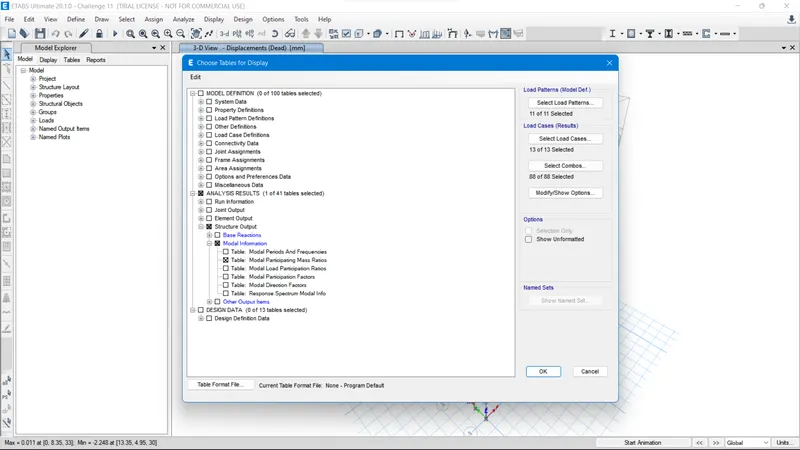
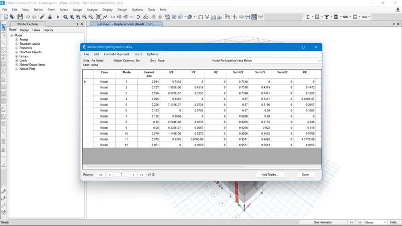
- Then we can see the Table of Model Participating Model ratios by click and selecting Display < Show Tables to open Choose Tables for Display.
- From the opened Tab, click and select Analysis Results < Structure Output < Modal information < Table Modal Paricipating Mass Ratios.
- Then the Modal paricipating mass Ratios Tab will open, we can see the Mass ratios for all the Modals in all directions.
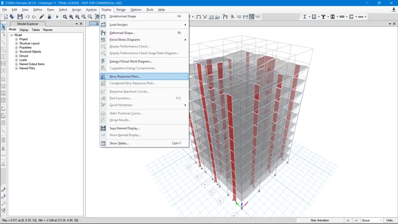
- To see the Maximum story drifts of the earthquake forces such as Eqx and Eqy we should open Story Reponse Tab.
- For that click and select Display < Story Response Plots to open Story Reponse Tab.
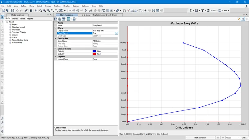
- After opening of the Story Response Tab, change Display Type = Max Story Drifts and Case Combo = Eqx to see the Maximum Story Drifts of the earthquake load force at the X direction.
- And here it was below 4. So it is safe.
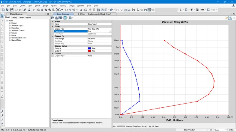
- Likewise to see earthquake load force at the X direction, change Display Type = Max Story Drifts and Case Combo = Eqx to see the Maximum Story Drifts.
- And here it was below 4. So it is safe.
RESULT :
Data required :
- Pinned support, Base + 9 Story (Ground terrace) + 1 Mumty.
- Column 450mm x 600mm, beam 400mm x 500 , Slab 150mm thick, shear wall 300mm thick.
- Live load 2.5 KN/m^2, Floor finish 1.5 kN/m, Wall load 5kN/m , Water tank 20K liter over mumty equivalent to 200 KN overall load.
Conceptual design considerations before analysis :
- Re-entrant and cutout check & modification (compromise)
- Vertical irregularity (soft story)
- Planar irregularity (Looks symetrical)
- 2% shear wall area with respect to building area (8m^2)
- Stiffness modifier for column, beam and shear wall (0.35 for beam, 0.7 for vertical)
Key points to remember while modelling :
- No slab, No wall load in ground floor.
- Proper end releases in beam.
- No interior wall load in terrace.
- Comparison on static and dynamic forces and revising the factor.
Checks after analysis :
- Model mass analysis for first 3 modes dominates at least 65% (Achieved for x-axis only)
- Mode-1 and Mode-2 differs by 10% (Achieved)
- Principle modes be greater than Torsional model (Achieved)
- Inter story drift ratio limited to 0.004 (Achieved)
- Axial stress in column and shear wall (Achieved)
- Base shear share between shear wall & columns (Not dual systems)