Structural Modelling using Etabs 2018
The architectural drawings for a G+7 residential building in zone 5 have been provided. The floor plan is the same for all 7-floor levels. Possible column positions have also been provided. Conceptualize a framing plan layout and then model the building in Etabs. The following architectural drawings have been provided:
- Typical floor plan – The location and thickness of the brick walls and the use of the
space (for estimating live load) can be obtained from this plan - A building section through the staircase and lift core is provided
- Parking layout on the ground floor – the column/shear wall arrangement must not
obstruct entry/exit of vehicles.
The following loadings are to be taken into account: - Brickwall made of AAC blocks
- Finishes – floor tiles of 75 mm thickness
- Live loads as per IS 875 part 2
- The water tank of 20 KL above the staircase at Mumty level
- Lift Machine room at mumty level above lift core
The structural model must comply with provisions of IS 1893 and IS 13920.
Run a modal response spectrum analysis and check analysis results of the etabs model for inter-story drift requirements, vertical & planar irregularities, minimum shear wall requirements, maximum axial load ratio for column and shear walls, an effective moment of inertia for beams
and columns etc.
Please note that the column positions shown in the architectural typical floor plan are only to provide an initial starting point for modeling. Participants will have to change its size, introduce shear walls, and add new vertical elements after running the analysis. You will have to run the analysis multiple times until a structural model is obtained that meets structural code requirements without compromising architectural functions. Also, there is no one ‘correct’ structural system for this challenge. There can be multiple possible solutions to this problem.
ANSWER:
COMPLETE STEPWISE PROCEDURE TO MODEL AND ANALYZE A BUILDING IN ETABS BASED ON THE ARCHITECTURAL DRAWINGS RECEIVED
The entire process can be divided into three phases. The first part specifically deals with the geometrical modeling of the structure keeping in mind the Architectural concept behind the building. Later in the second part, loads can be applied to the initial structural model and analyzed the same as per the codebook. At last, various checks have to be made from the analysis results in order to ensure the overall safety and integrity of the structure. And thankfully, all these steps can be carried out using ETABS with high precision and in less time. Thus, the same is executed below in a stepwise manner.
PART ONE: Carrying Out the Geometric Modeling of the Structure as per the Architectural Concept.
- Open up the Architectural Plan of the Building
- The AutoCAD file along with the plan screenshots has been attached to the question.
- So, we just have to download and save it to the desired location in our system.
- So, the same was done, and below is the Architectural plan, and the sectional elevation of the building to be modeled and analyzed using ETABS.
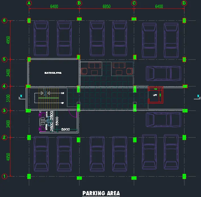
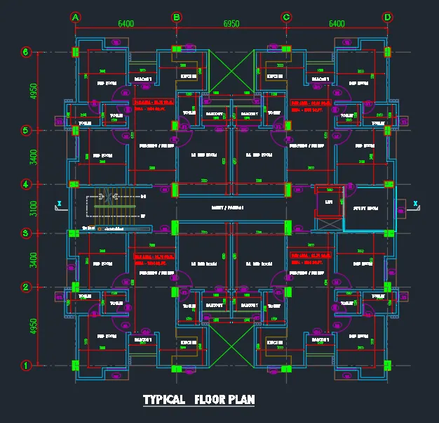
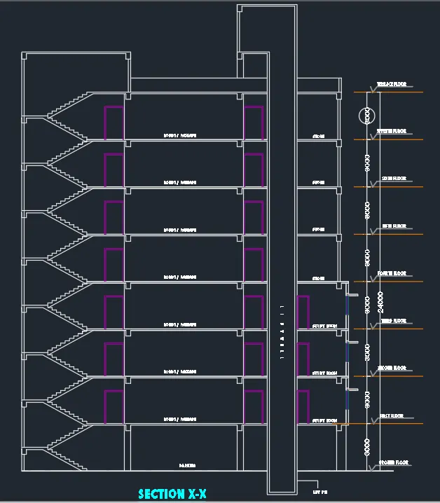
- Initiate the Structural Modeling Using ETABS
- The first thing we need to do when we open up the ETABS software is to specify the codes and specifications to be followed for the project.
- So, do just that by adding the relevant IS codes like IS-456, IS875, etc.
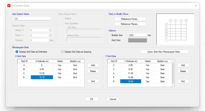
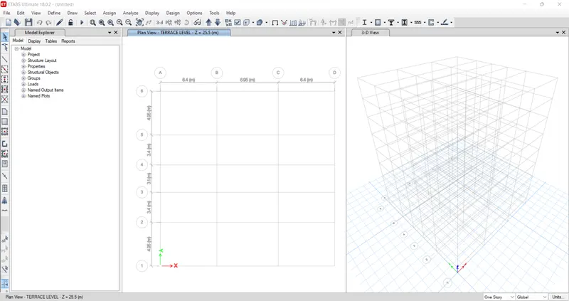
- Then, we need to adjust the grid and story system strictly as per the Architectural drawings received.
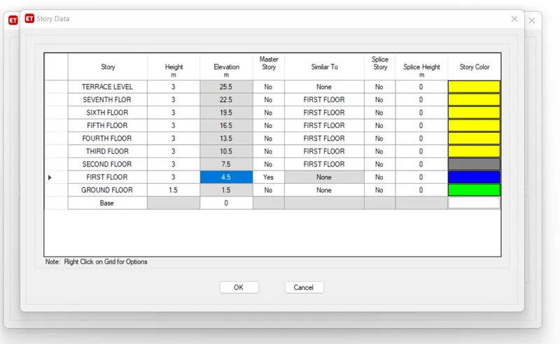
- Then, based on the sectional elevation, we can set up the story data in ETABS and specify the height of each floor, as well as the master story that is the first floor and all other floors, replicating the same typical floor plan layout.
Entering the IS-Codes
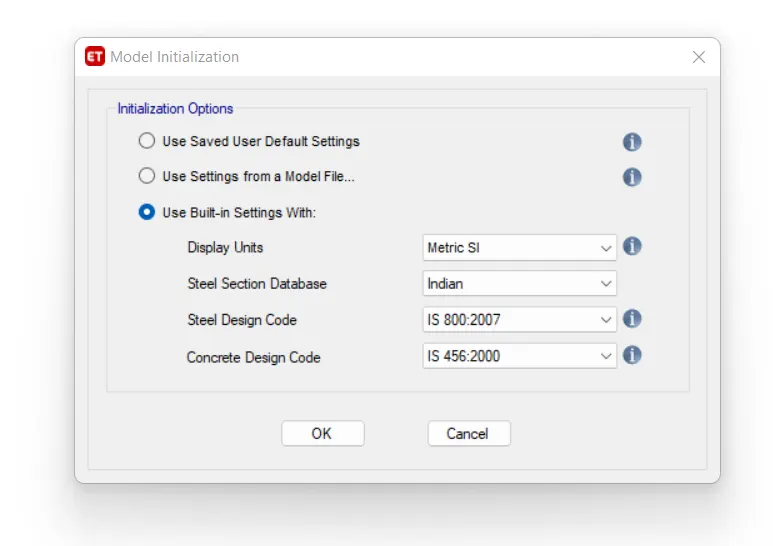
Custom Grid Data
Custom Story Data
Initial Grid and Story Data Setup
- Define Materials as well as Section Properties
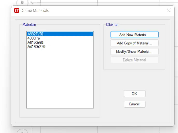
- Now that we have laid down the grid and story setup, we have to define the sections and materials to apply to all the grid points.
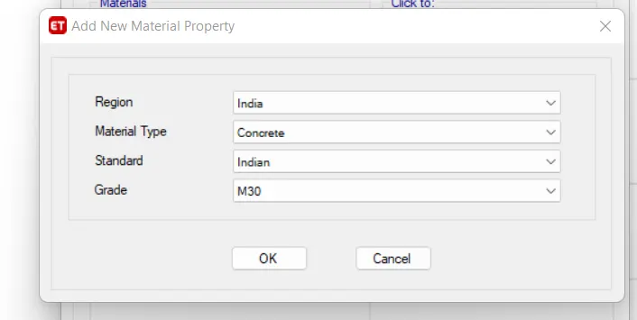
- So, go to define>material properties>concrete>M30.
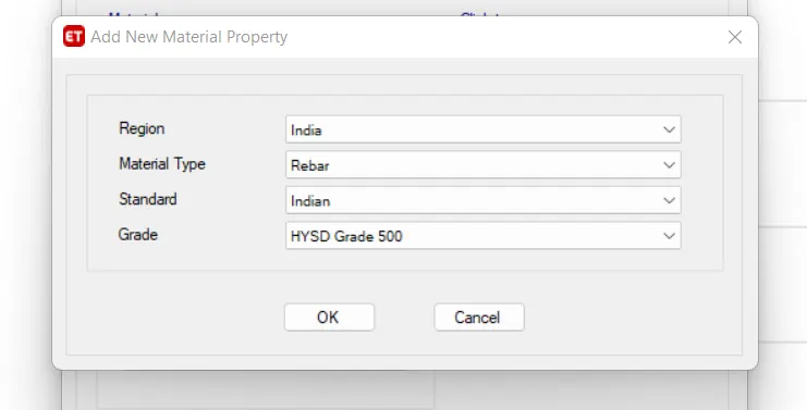
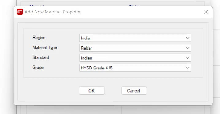
- Similarly, define>materials porperties>steel>HYSD500 for longitudinal reinforcement, HYSD415 for shear reinforcement.
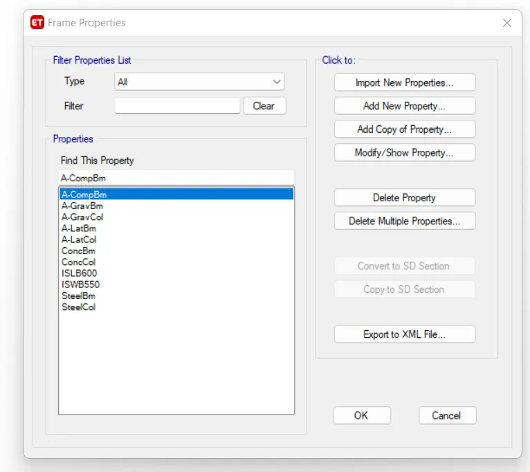
- Also, definre>section porperties>concrete rectangular>beam and columns of the initial sizes and reduced moment of inertia.
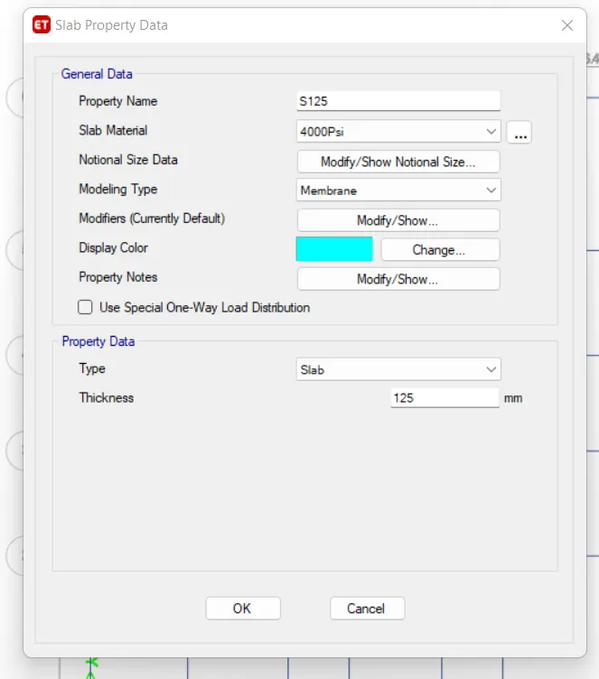
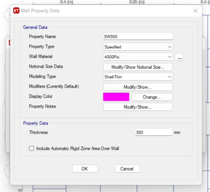
- In addition, define the slab section and wall section of appropriate thickness. In our case, we have chosen a 125mm thick slab and a 300mm thick shear wall for our structure.
Define Materials
M30 Concrete
HYSD 500 for Longitudinal Reinforcement
HYSD 415 for Shear Reinforcement
Define Frame Properties
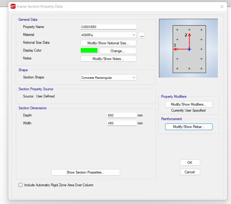
Column 450 x 650
Slab 125mm thick
Shear Wall 300mm thick
- Drawing Beams, Columns, Shear Walls, and Floors
- After defining the material and section properties, it's time to start drawing the structural elements using the draw tools in ETABS.
- So, on the left vertical tool panel available on your ETABS screen, you can select any option like quick draw beams, columns, floors, and walls.
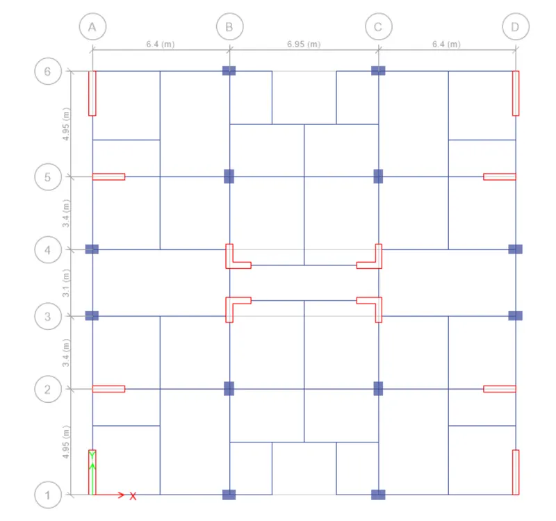
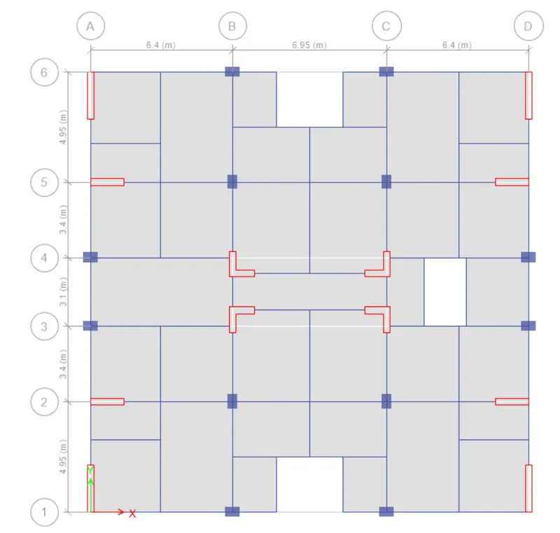
- Hence, the same tools were used and the geometric modeling of the given building was completed as inserted below.
- Also, we need to make sure of the structural eccentricity while placing the shear walls along the X and Y axes.
- At the same time, ensure that the shear wall area provided is roughly around 1.5 - 2% of the total floor area in either direction.
BEAM COLUMN ARRANGEMENT
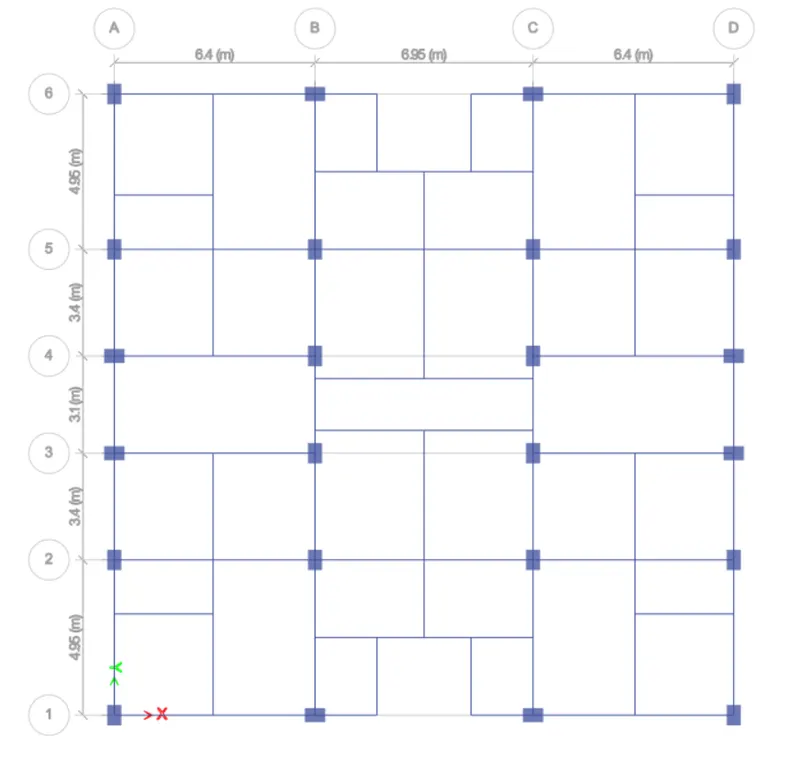
SHEAR WALL ARRANGEMENT
COMPLETE STRUCTURAL MODEL WITH FLOORING
PART TWO: Applying All the Loads on the Model that are Expected During the Service Period of the Structure.
- Define and Assign Gravity Loads
- It is always a good idea to assign gravity loads separately from the lateral loads.
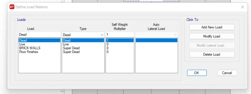
- So, go to define>load patterns>dead, live, brick wall, floor finishes, etc.
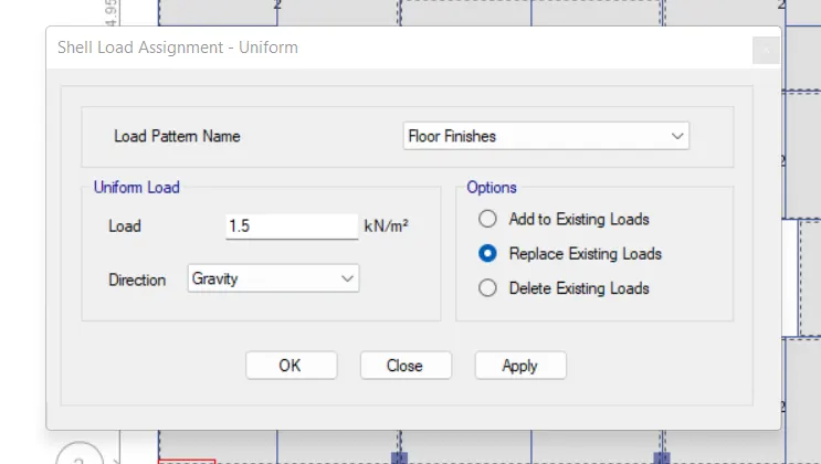
- Also, make sure to select the super dead category while adding the brick wall and floor finishes loads.
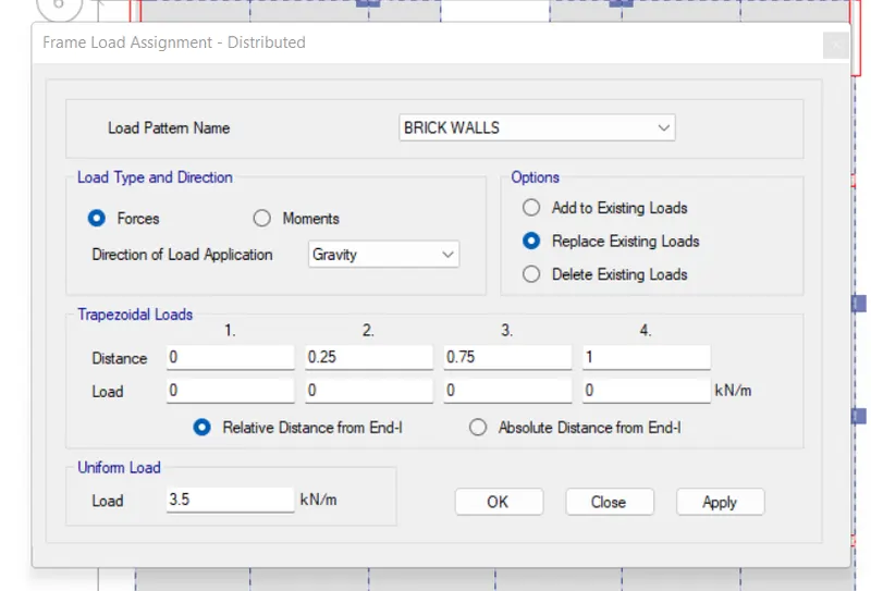
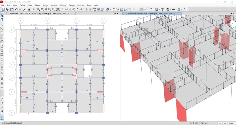
- Now, you need to assign these loads. So, select all the beams>go to assign>frame loads>brick walls>3.5KN/m
- The value of 3.5 KN/m is derived from the density calculations as we are using AAC block as the masonry material.
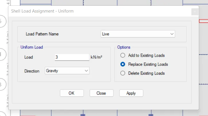
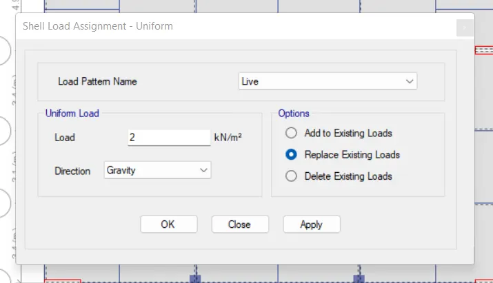
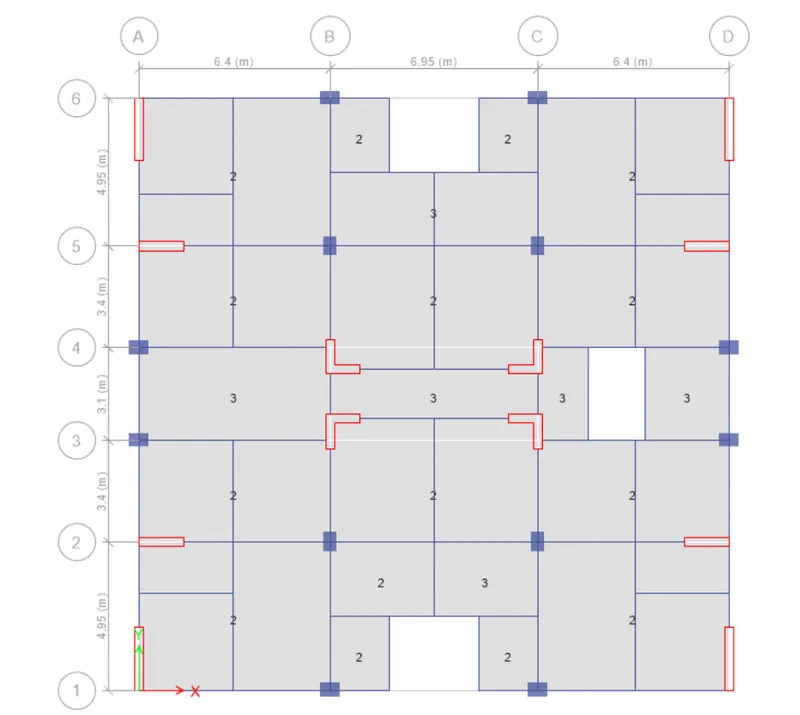
- Similarly, assign live load strictly as per the given conditions in IS-875 part II.
Define Load Patterns
Assign Brick Wall Load
Live Loads
Floor Finishes
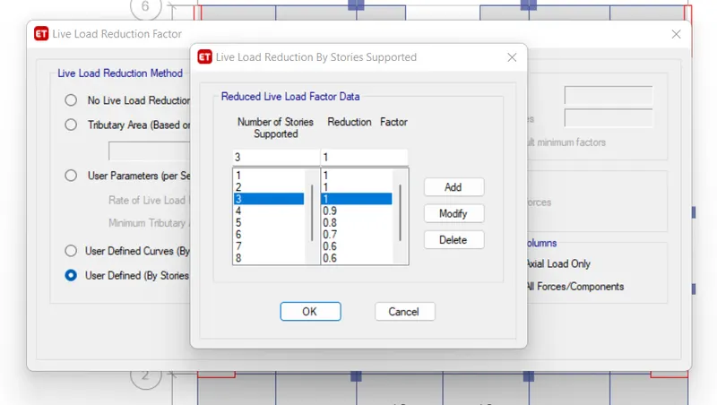
Live Load Reduction As per the Codebook
- Define Lateral (Earthquake) Loads
- The process of defining and assigning the lateral loads is fairly the same as we did for the gravity loads.
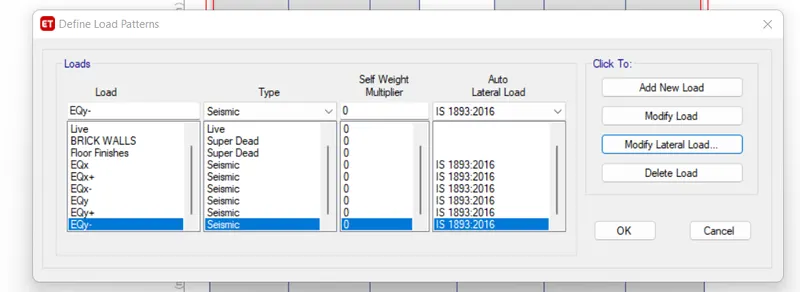
- Hence, a similar procedure is followed and the following lateral loads are defined and assigned.
Define EQ Load Patterns
- Define Mass Source
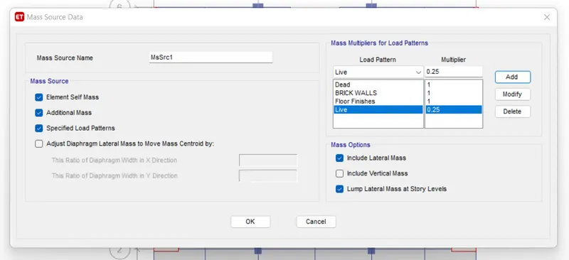
- We need to define the mass source for all the lateral load patterns we've just added.
- And as per the IS-Code, the mass source shall include 100% of all the dead and super dead loads. On the other hand, it will include only 25% of the live loads.
- So, the same has been done as shown below:
- Add up the Modal Case
- After defining the mass source, we need to add up a modal load case with the same mass source we just defined.
- So, simply go to define>load cases>add>modal>define the same load patterns as for the mass source.
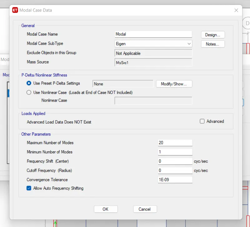
- Response Spectrum Analysis
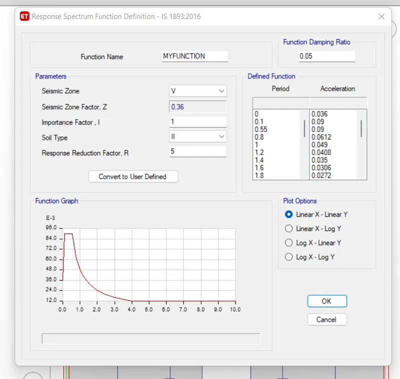
- Now that load the linear loads and cases have been completed, it's time to go ahead with the dynamic response spectrum analysis.
- For this, first, go and define a new function that contains the response spectrum analysis.
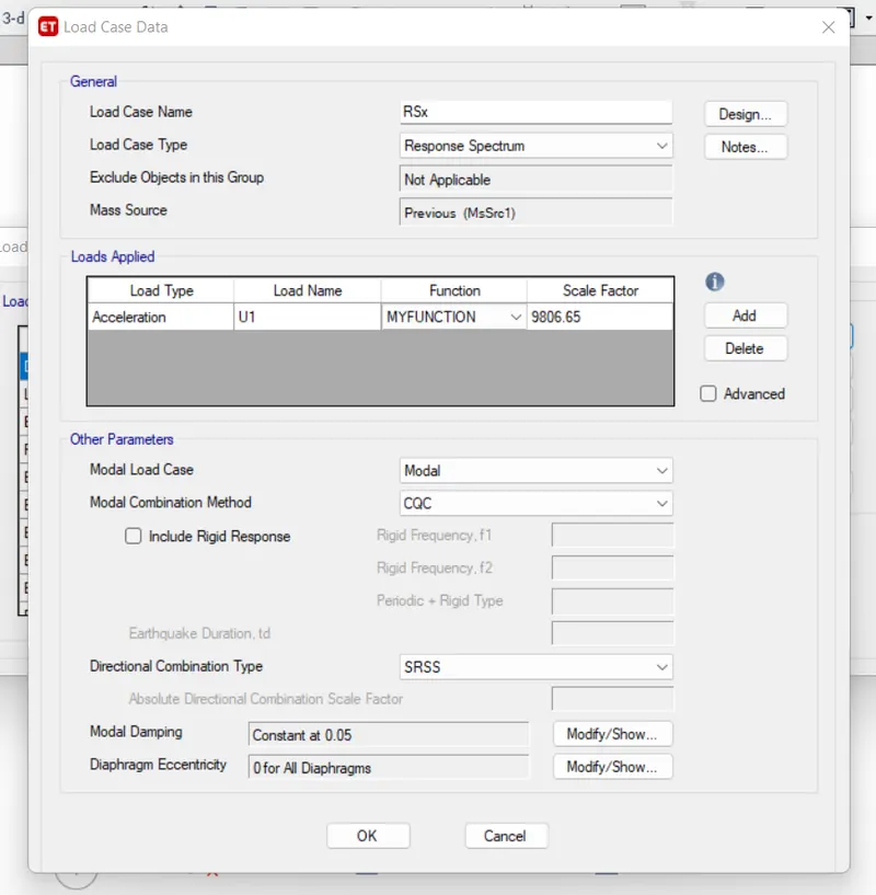
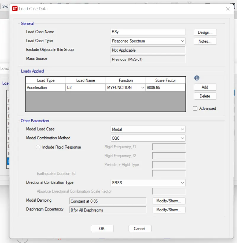
- After adding the new function, we need to add the response spectrum load cases in the X and Y directions.
- And to do that, go to define>load cases>add new>response spectrum>select the function defined in the previous step and done.
- Also, you need to repeat the process twice for both X and Y directions.
Response Spectrum Function
Response Spectrum Load Case in X-direction: RSx
Response Spectrum Load Case in Y-direction: RSy
- Generate Load Combinations
- Since we are done with all the load patterns and cases, we can now go ahead and generate the automatic load combinations in ETABS.
- And to do that, simply go to define>load combinations>default load combinations and that's it. All the relevant load combos will be program generated that you can further alter as per your need.
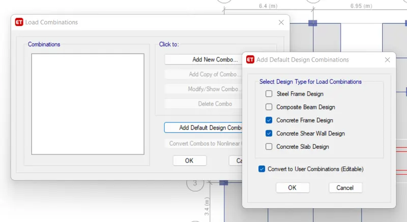
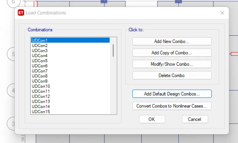
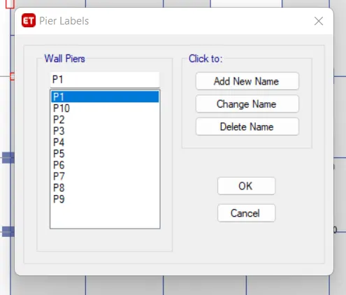
- Define and Assign Pier Labels to the Shear Walls
- Go to define>pier labels.
- Click on add button to add as many labels based on the number of shear walls in your model.
- Then, select the shear wall>go to assign>wall sections>pier labels>choose the label number>press OK.
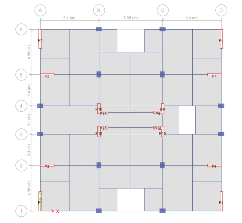
- Assign Diaphragm
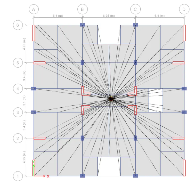
- In order to locate the center of mass for our model, we need to assign the diaphragm to it and ETABS locates it automatically.
- So, just go to assign>diaphragm>select the default D1>press ok.
- After pressing OK, you will be able to see the center of mass on your model as shown below:
- Check the Model and Run the Analysis
- After assigning the diaphragm, the modeling part is 100% complete and now we can run the analysis.
- However, we need to check the model for any geometrical errors before running the analysis.
- So, go to the analyze tab and click on the check option.
- ETABS will look for any errors and display them on your screen if there is any fix needed.
- So, after completing this step, you can safely run the analysis by hitting the play button on your ETABS scree.
PART 3: Reviewing the Analysis Results to See if the Model is Structurally Stable or does it need a Revision.
1. Base Shear Check
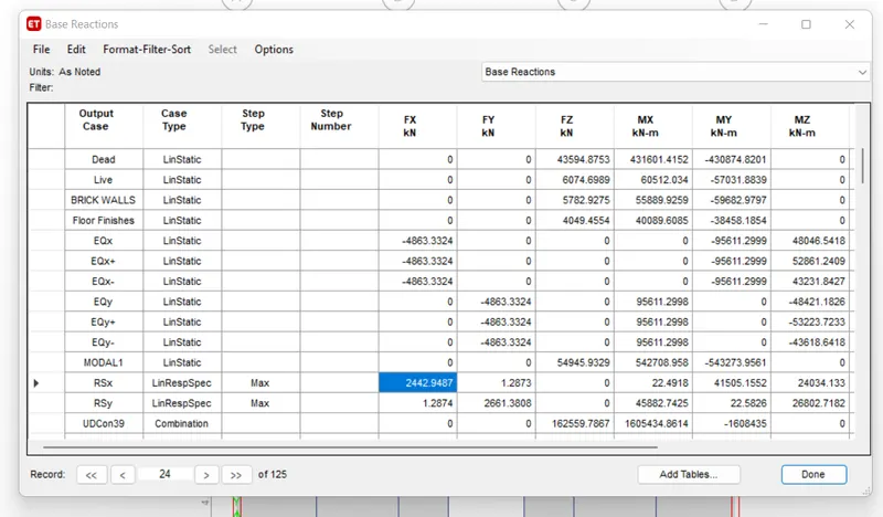
- Compare the Base Shear Obtained from Linear Elastic Analysis VS the Response Spectrum Base Shear
- So, we need to compare the base shear given by ETABS for both cases that is linear as well as the dynamic response spectrum analysis.
- And as per the codebook, the response spectrum base shear must be at least equal to the same obtained by the linear analysis.
- So the below images are inserted from the results to see the difference between both these values in the X and Y directions.
- Base Shear Scaling
- As can be seen from the comparison, response spectrum base shear is significantly less than that of the EQx and EQy.
- So, what we need to do now is increase the scale for the response spectrum load cases in X and Y for it to match the base shear value.
- And to do that, simply divide both values and multiply the factor with the initial scale adopted while defining the response spectrum load cases.
- So, in our case, we have done the following calculations.
Scale Factor for RSx = Linear Elastic base shear/ dynamic base shear = 4863/2442 = 1.9914
Multiplying it with the initial scale, we get a total scale = 19528.96
Scale Factor for RSy = Linear Elastic base shear/ dynamic base shear = 4863/2661 = 1.8275
Multiplying it with the initial scale, we get a total scale = 17921.73
Now, we need to unlock the model and rerun the analysis and check if the values have been matched or not. So, the same was done and the output is inserted below:

As can be seen from the above picture, both the base reactions have reached the same value. Hence the IS-Code specification regarding the base shear has been met.
2. Modal Participation Ratio Check
- As per the IS-Code, the participation of the rotational axis that is Uz should not be the governing mode within the fundamental modes.
- So, we need to check the participation ratio of the two translational modes for the fundamental modes.
- So, we can generate the table in ETABS that showcases all the details regarding the modal participation ratio.
- And to do that, go to display>show table>structure output>modal response>modal participation ratios>OK.
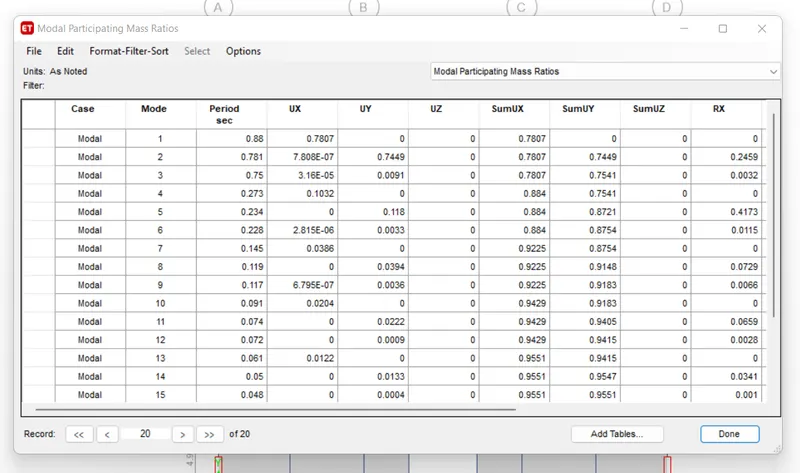
As can be seen from the table, our model is safe.
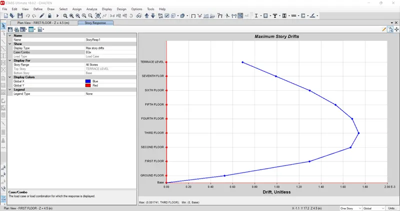
3. Check for the Inter-Story Drift
- The maximum allowable interstory drift as per the IS-1893 is of 0.4%.
- So, to check if our building satisfies the stated limit, go to display>story response plots.
- Then from the dropdown list, select EQx and EQy to check the drift in both the respective directions.
- Again, the value should not exceed 4%.
Story Drift in the X-direction
Story Drift in the Y-direction
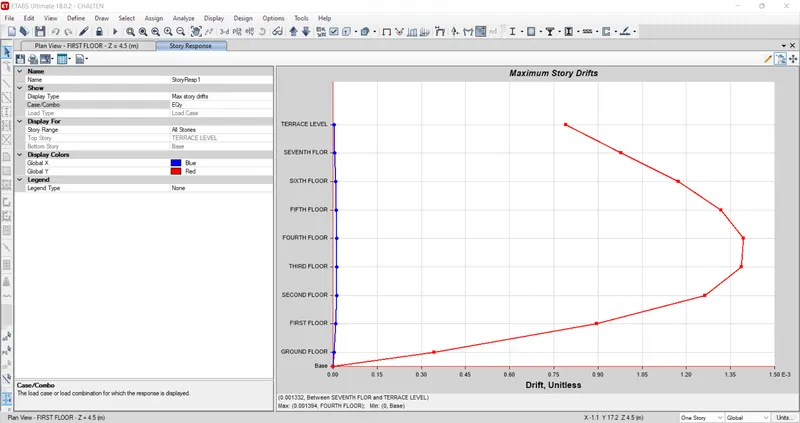
As can be clearly seen, the story drift for both directions in our building is within the specified limits. So, our model is good to go.