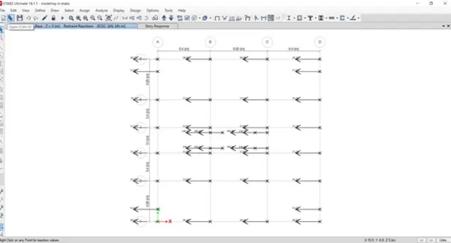
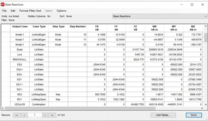
Structural Modelling using Etabs 2018
Aim:
To model and analysis the G+7 residential building from the given architectural drawing using the ETABS 2018
Production:
Step 1
First we have to open the etabs software
Next click on the file option at the left side top corner and select the new model
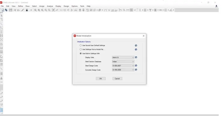
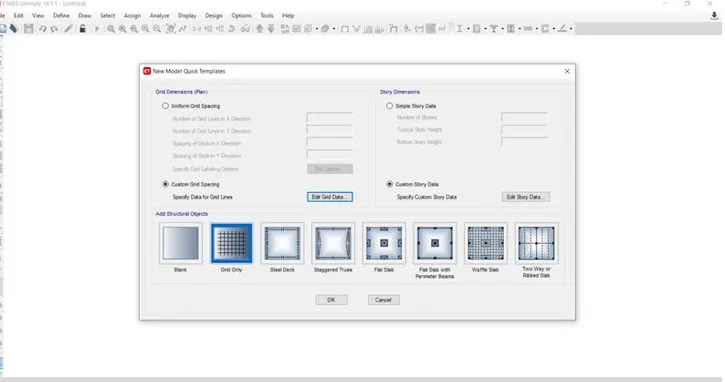
Step 2
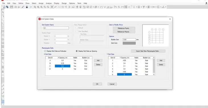
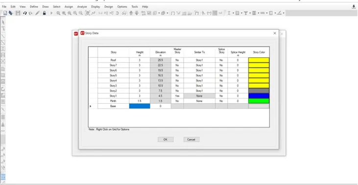
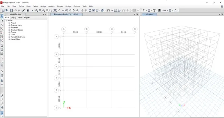
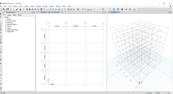
Next the plan views are visible in the etabs screen
Next we need to open the 3d view
Step 3
Next we need to define option and select material properties
After selecting the material properties the new tab appears then we add new material by selecting the add new material option
Step 4
Now we need to add material type as concrete and grades as M25
Next we need to check the material property data

Step 5
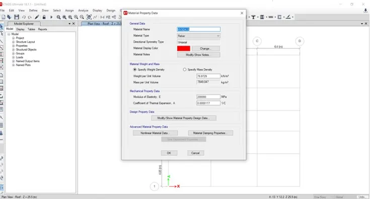
Now we need to add new material type as rebar and grade as HYSD Grade 415
Next we need to check the material property data
Step 6
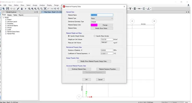
Now we need to add new material type as rebar and grdes as HYSD Grade 415
Next we need to check the material property data
Step 7
Now we need to select the section properties and click on the frame section
Step 8
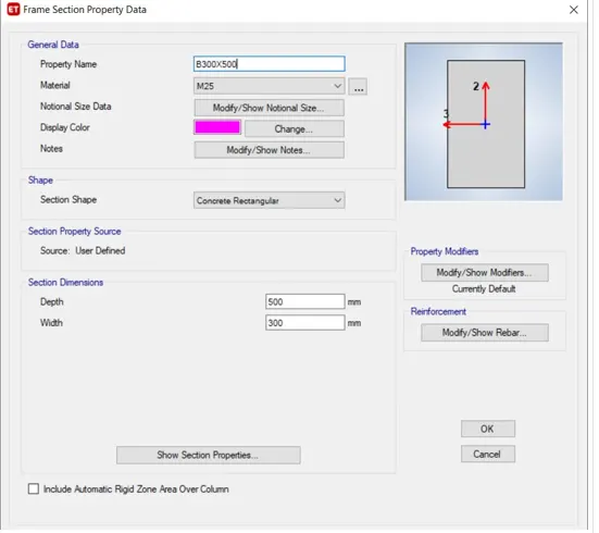
After selecting the frame sections the new tab will be visible in that we need to select the add new property
After selecting the add new property the new tab appears
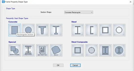
In that new tab we select the rectangular shape type in concrete
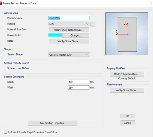
Next the frame section property data will be visible in that we add beam size as B250x450
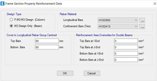
Next we need to select the modify /show rebar option
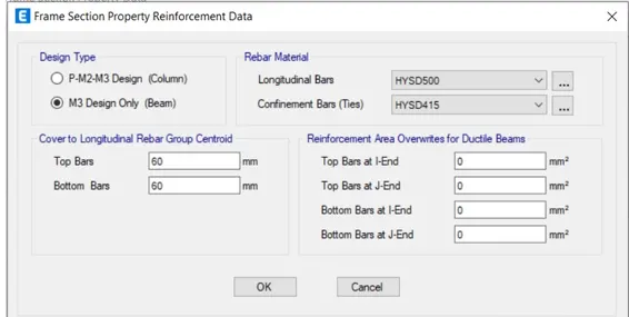
After selecting the modify/shown rebar option the new tab apperas in that we select the design type as M30 design only
Next we select longitudinal bars with the grade of HYSD500
Next we select confinement bars with the grade of HYSD415
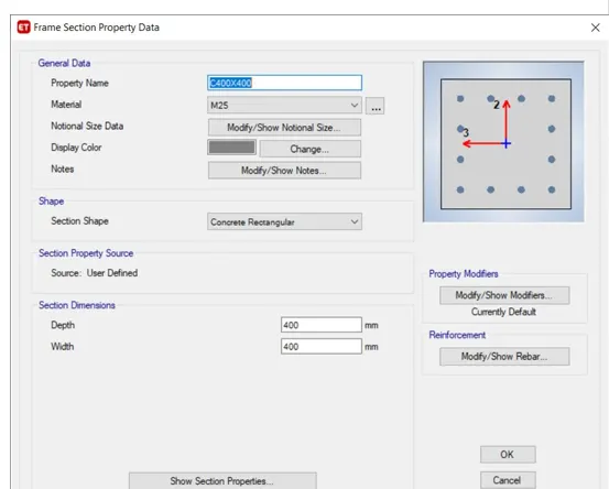
Again we have to select rectangular shape type in concrete
After selecting the modify/shown rebar option the new tab apperas in that we select the design type as M30 design only
Next we select longitudinal bars with the grade of HYSD500
Next we select confinement bars with the grade of HYSD415
Step 9
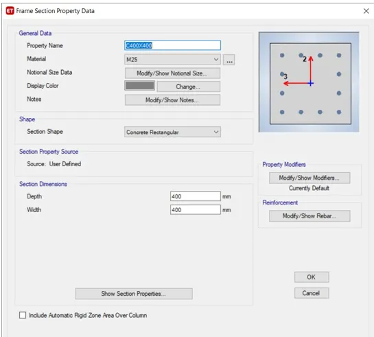
Next we have to add the column size as 400x400 in the frame section property data
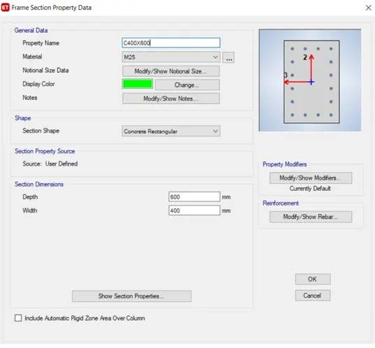
Again we have to add the another column size as 400x600 in the frame section property data
Step 10
Next we select the slab section option from the section proprties
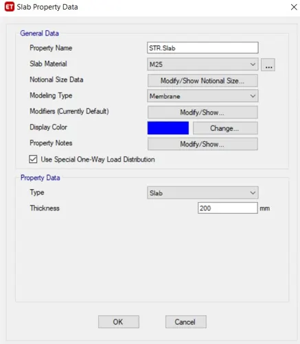
Next the slab properties tab will be visible in that we select the modify/show property option
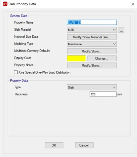
In that we need to put the slab name as slab 125 it means slab with the thickness of 125mm
And we have the concrete grade as M25
Next we have to click the ok option
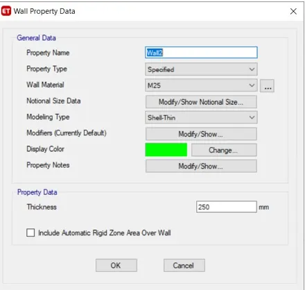
Step 11
Next we have to add the wall properties in the wall property data
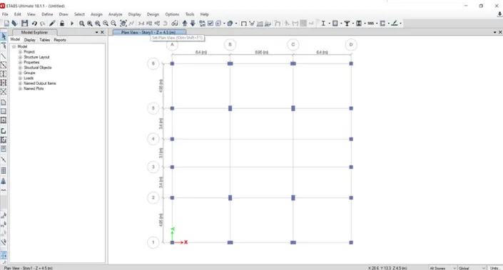
Step 12
Next we need to add the columns using the quick draw column option
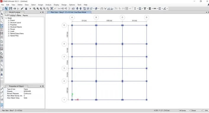
Step 13
Next we need to add the beams using the quick draw beams option
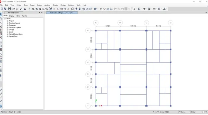
Step 14
Next we need to add the secondary beams using the quick draw beams option
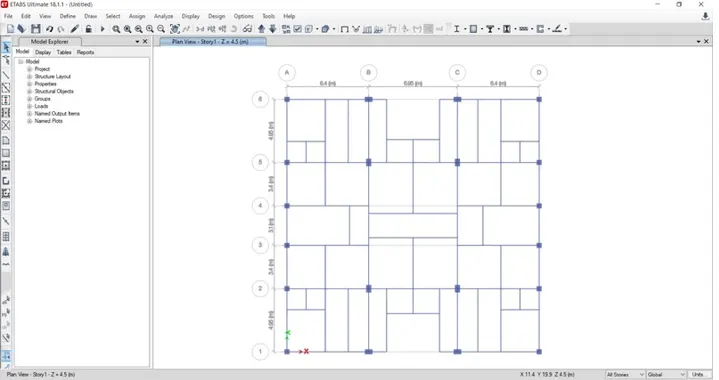
Step 15
Next we add the shear walls in required locations in the residential building
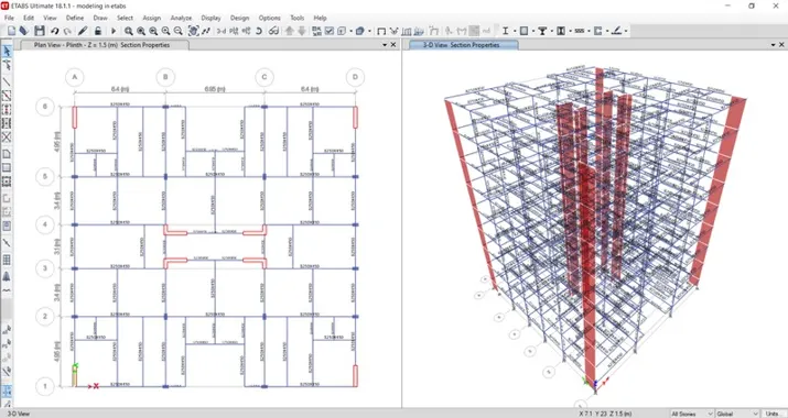
Step 16
Next we need to add the slab using the quick draw floor option
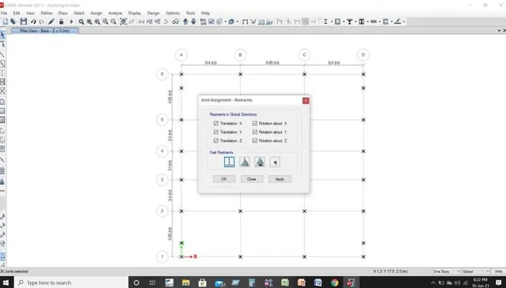
Step 17
Now we go to the base plan and select all base joints
Next we select the restraints from joint option
Now we need to select the fixed joint and click on apply and then click on close button
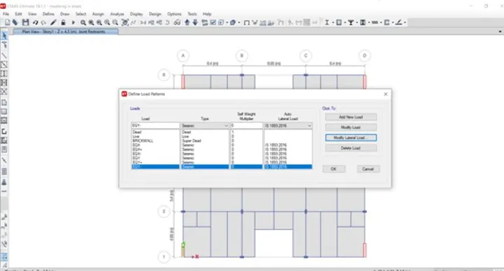
Step 18
Next we need to select the load patterns from the define option
Now we should add dead load ,live load,brickwallload,and earthquake load
Step 19
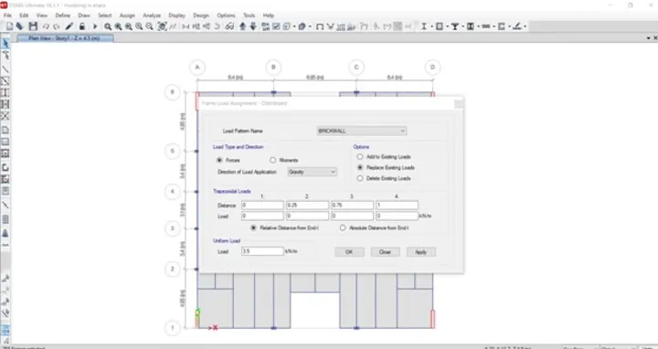
Next we need to select the distributed load from the frame loads
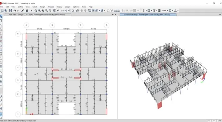
Then after the new tab will appear in that we select load pattern as brickwall and we take uniform load as 3.5KN/m and then click on the apply button and close
Step 20
Next we have to click on the assign option and then select shell loads from the shell loads we select the uniform option
Step 21
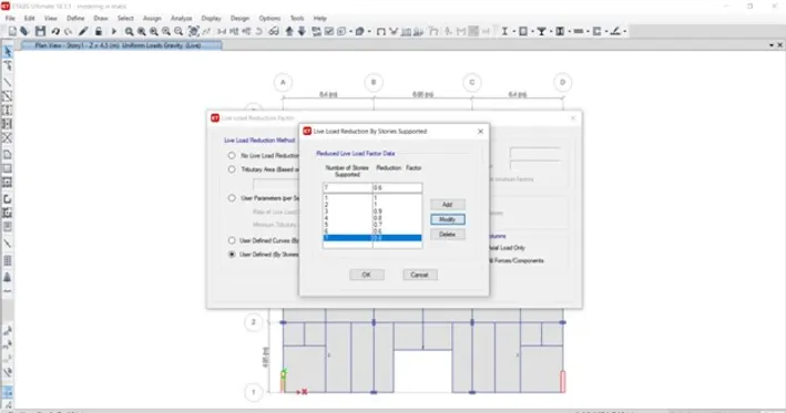
Next we have to select live load reduction factors from the design option
Now we add the reduction factors by decreasing 10% from 1st floor to 7th floor
Step 22
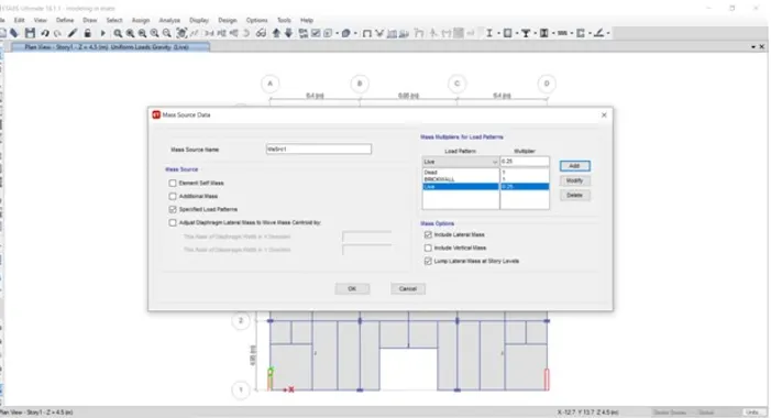
Next from the define option we select the mass sources
Next we add the load pattern in the mass source data
Step 23
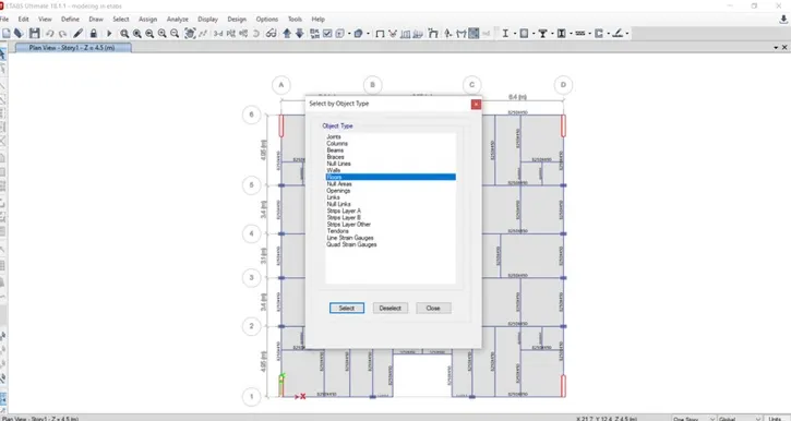
In the select option we select object option
After selecting the objet type option the new tab will be visible in that select the floors and click on the select button and close
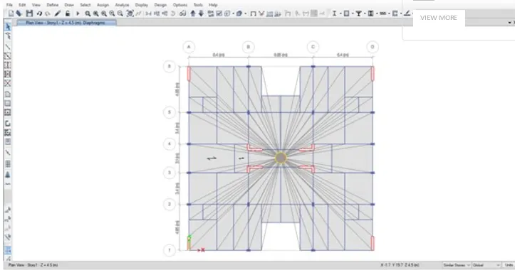
Next we have to select the diaphragms from the shell option
After selecting the diaphragms the new tab will appera in that select D1 and click on the apply button and close
Step 24
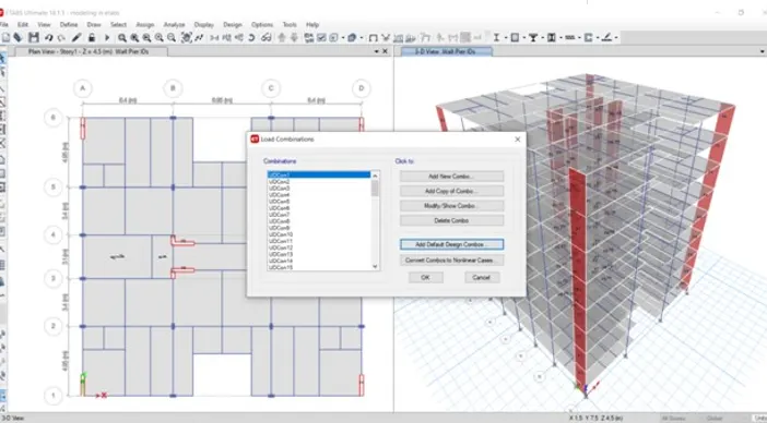
Next we have to select the pier label from the shell option
Before going to shear wall design we have to assign the names for the shear walls (P1,P2,P3,P4,P5,P6,P7,P8)
Step 25
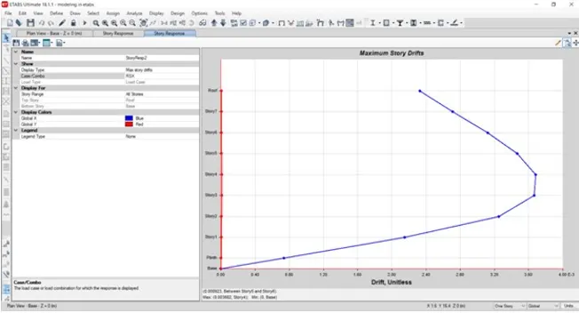
Shown the table