Structural Modelling using Etabs 2018
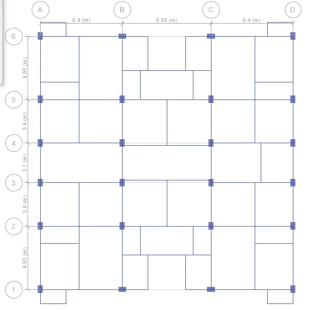
Aim - Model in etabs and analyse the according to given architectural plan and add shear walls
Procedure -

Open a new model in etabs
Give units as metric SI
Steel as indian
Design code as IS 800 : 2002
Concrete design IS 456 : 2000
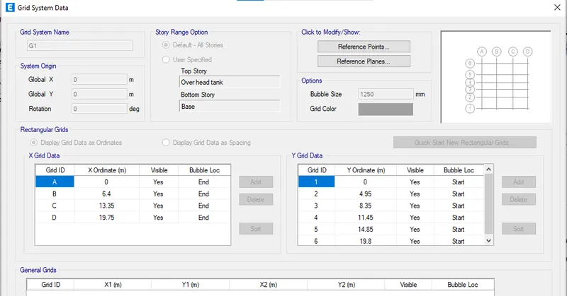
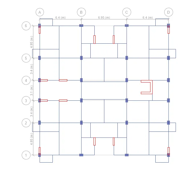
Then give grids and story data
Give spacing in X and Y direction for the grids
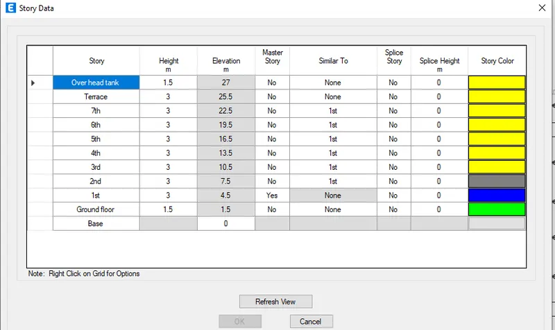
Then gove story data
From base to plinth give height as 1.5m and remaining all floors as 3m
Give story 1 as master story
Then give remaining all as similar to 1st story
Give material properties
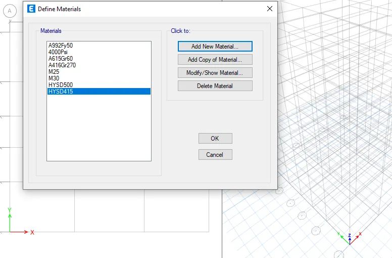
In the define tab go to material properties
Add new material India concrete and grade as M30
Again add new material
Material type as rebar , indian standard and grade as FE415 and HYSD500
Give beams,coloumns and slab
In the define tab select sectional properties and framed sections for beam and coloumns
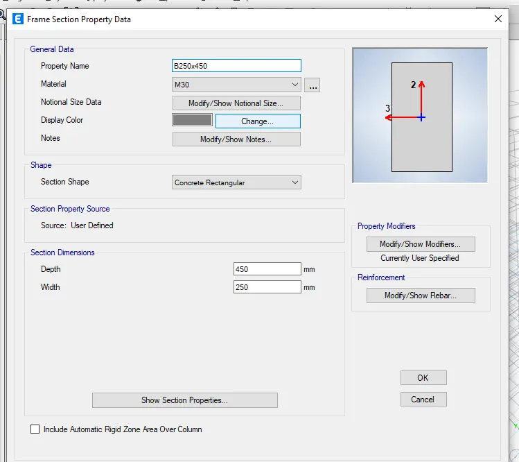
Add new propert and rectangular concrete
Give property name as B250x450
Give depth as450 and width as 250 as given
In the same process add new propert as coloumn and name it as C400x600 and
Give depth as 400 and width as 600
Because we are modelling the lateral forces also
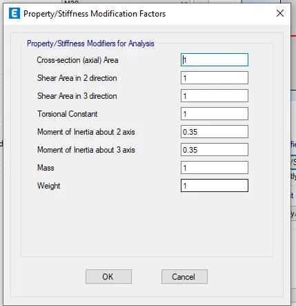
Give moment of inertia in 2dir and 3dir beams-0.35 and coloumns - 0.7 in the modifiers
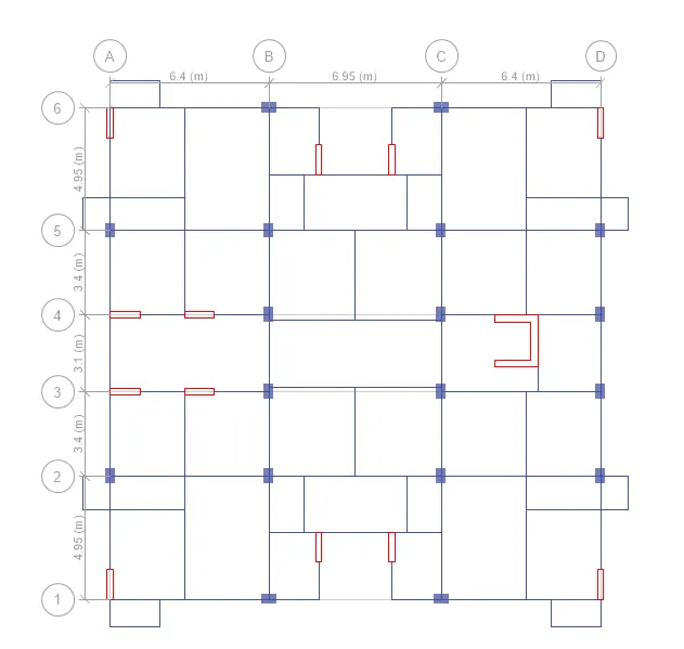
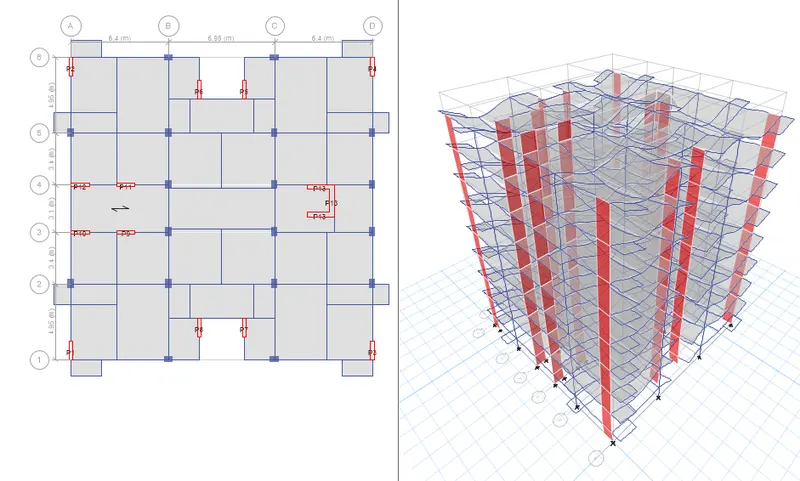
Then draw beams at the grid lines
Secondary beams
Add the secondary beams at the places where wall present in the architectural plan
And add the beams at the balconies according to architectural plan
Use replicate and edit frames to draw the secondary beams
For slab
In the define tab select sectional properties and select salb sections
Add a new property
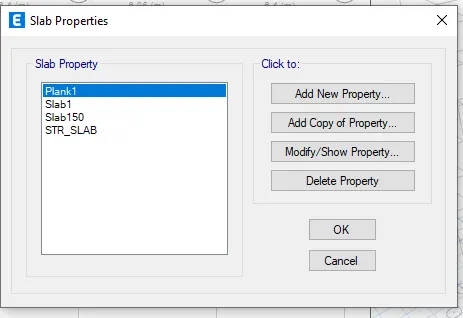
Then rename as S150 and give modelling type as membrane and give thickness as 150 and OK
Add the stair case slab also
But give thicknes of 175 and give one way
Shear wall
In the define tab sectional properties and wall sections
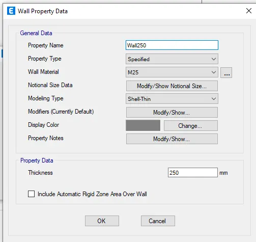
Give material as shell thin and thickness as 300
Then start modelling
Go to any plan view and select all stories
Select quick draw coloumns and select C400x600 and draw at the grid points
Then select quick draw beams and select B250x450Then draw beams at the grid lines
Secondary beams
You can also replicate the beams and coloumns by giving offset and no of times
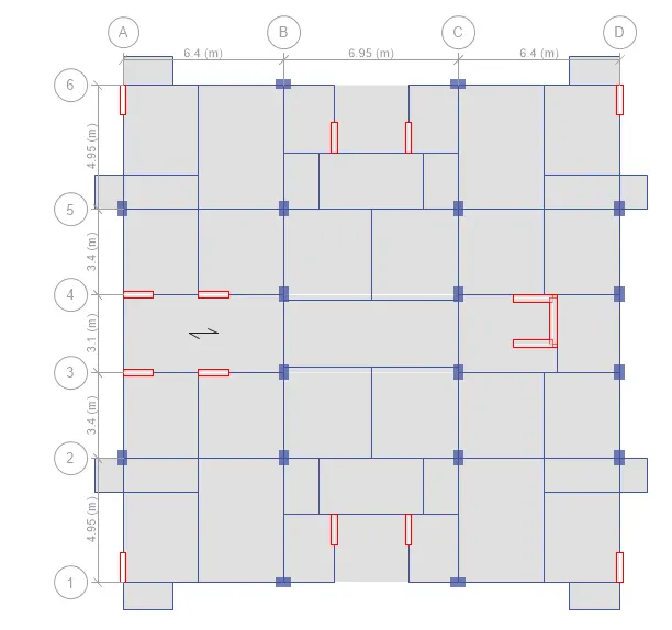
Add slab
First select similar stories
Go to any plan view and select quick draw floors and select S150
Select the space where slab to be laid
In the same way add the stair case slab
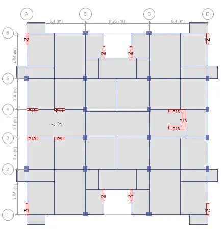
Add shear walls also
There is a tool under the salb
Draw in the way that it should be 1.5% of area
Where you drawn the shear walls you can delete the coloumns in the elevation view
There is also option wall stacks i the draw tab and you can select the desired shape
This is useful in the lifts and staircases
Then assign the loads
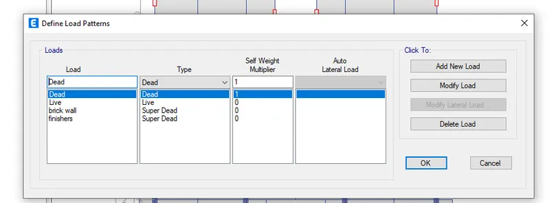
In the define tab select load patterns
Select dead load with multiple of 1
Add live load of multiple 0
Wall load as super dead load and multilpe 0
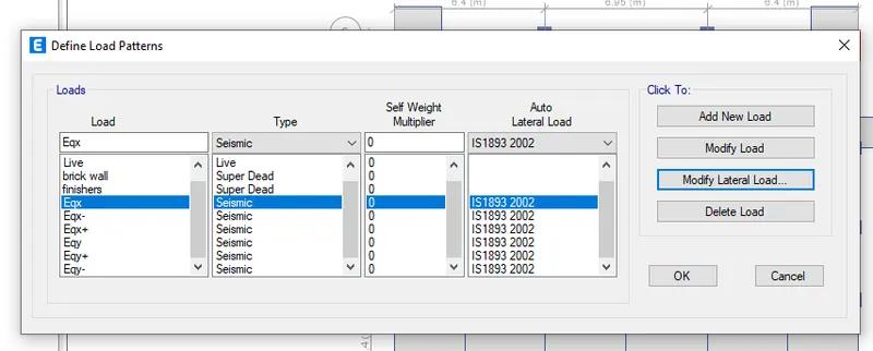
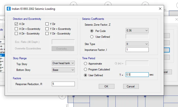
Eq in X directiion of seismic load and code of IS 1893 2016
Eq in Y directiion of seismic load and code of IS 1893 2016
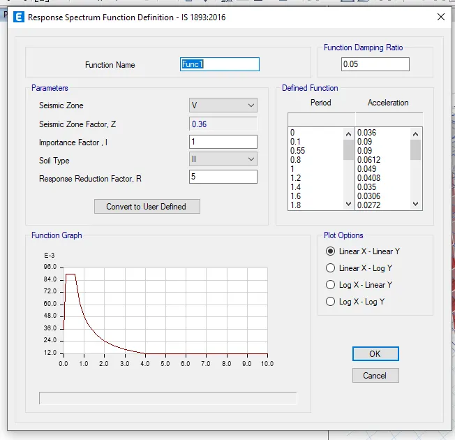
Then select Eqx and modify and select zone as 2 and I factof as .16
Earthquake loads
Time period
From the formula from code 0.09h/`sqrtd`
We get 0.5 sec this is time period in the Eq in all directions because it is symmetrical
Respose factor R
In the shear wall system - 4 and dual system - 5
Importance factor - 1 (Residential building ) IS1893
In the earthquke forces
Then OK
Assign live loads
Select all the slabs
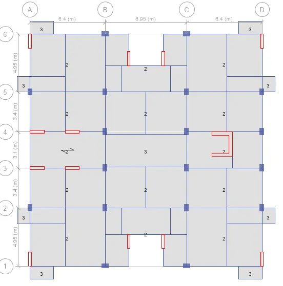
Then assign shell loads and uniform loads and as live and give value of 3KN/M at balconies and lobbys
In the rooms add 2Kn/M
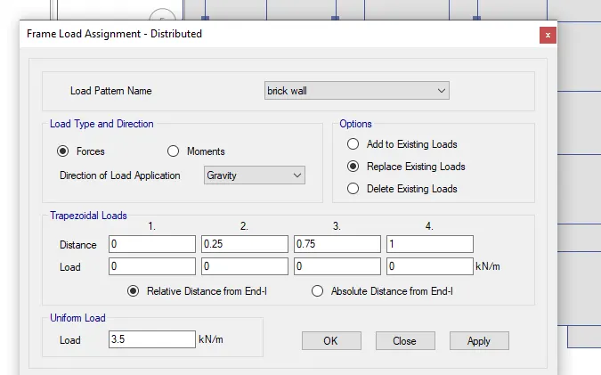
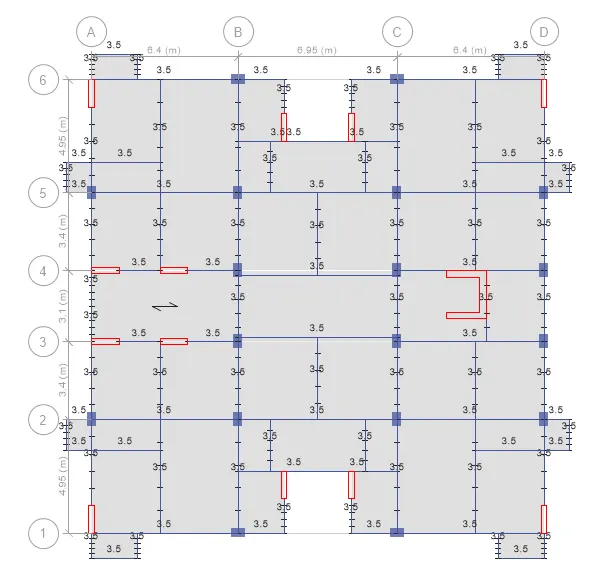
Then assign wall loads
Select all beams
Then assign and frame loads
Then UDl and give value as 3.5
Reduction in live loads by floor to floor
As the floors increases the live loads decreases
After the second floor the live load decreases to 10% till 6th floor as 40% and same for all the above floors
You can edit in desing tab live load reduction factor
Keep user defined and change as defined
Mass source
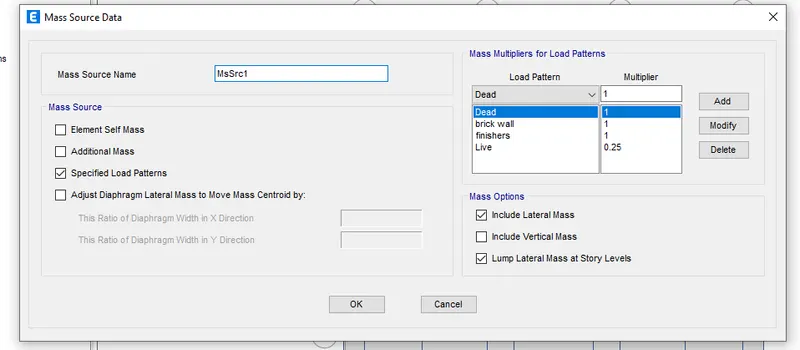
For earthquake load we have to assign mass source
Define and mass source
Select specefied load pattern and Ok
Now generate load combinations
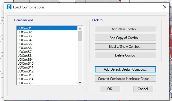
Define tab and load combinations and select default design combinations
Then select concrete frame design and edit table and OK
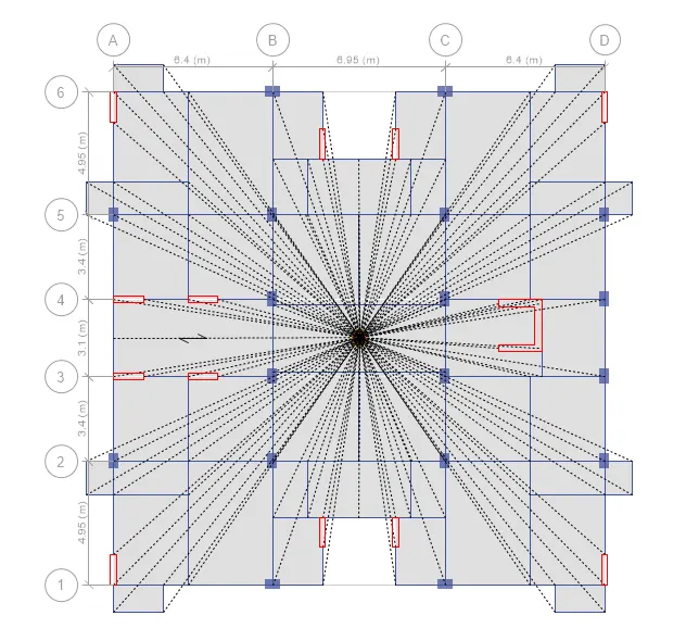
Diaphragm
Select all the floors
In the assign tab and shell tool and select diaphragm
You can see the eccentricity of the structure which is useful in lateral loading
We can check the model cases in define
Then analyse the structure by clicking run analysis key
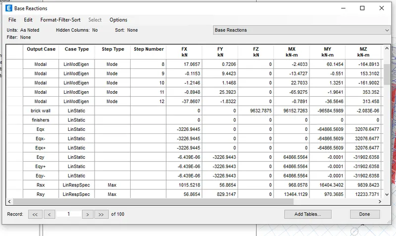
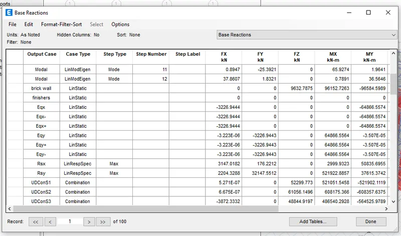
Check the base reactions
We got the base reaction of - 3226 in both sides (Eqx and Eqy)
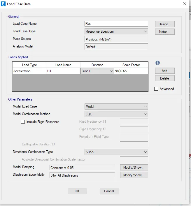
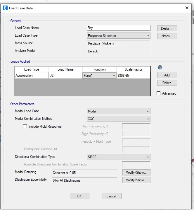
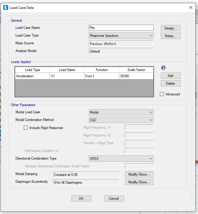
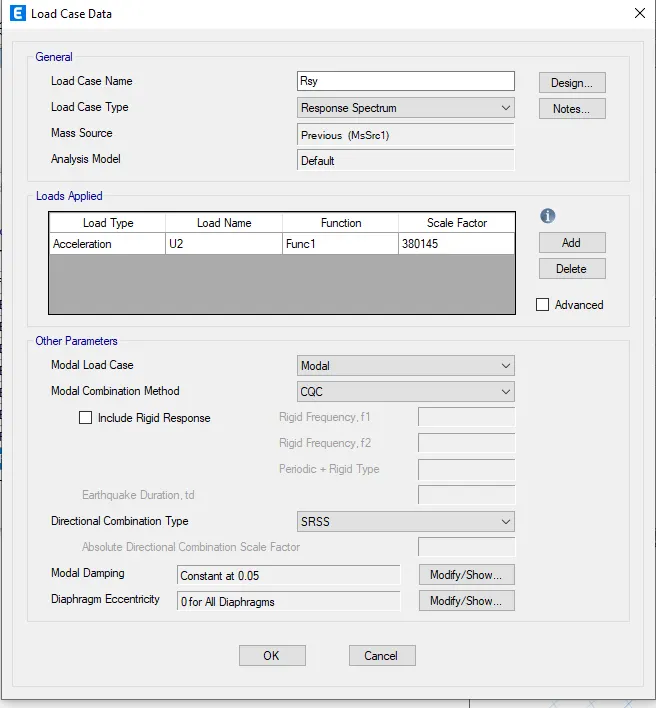
Check the scale factor in Rsx and Rsy
We got Rsx - 1015 and Rsy - 829
3 times of X axis and 3.8 times Y axis
So add to the Scale factor in Rsx and Rsy to 9806 which is default
Re run the analysis and check the Response base shear which we got the nearly value to 3000
Modal participation ratio
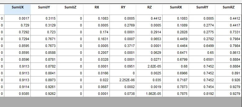
In the tables and structural output we have modal participation ratios enter to display table
In the sum of X and Y axis check where 90% is achieved
It is achieved at mode 12
But Rx and Ry achieved at 16 so 13 modes are eneough
Story reeponse plots
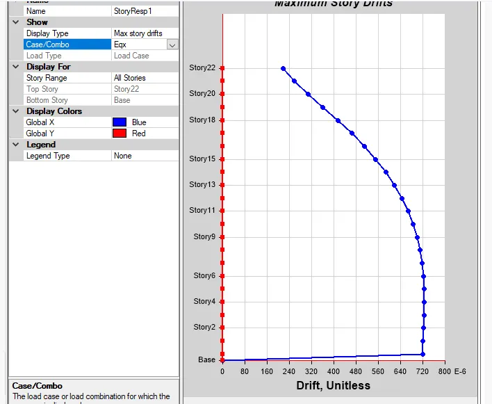
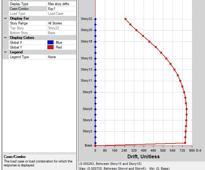
In the story response plots inerstory srift
In the Eqx and Eqy both are less than 4 OK
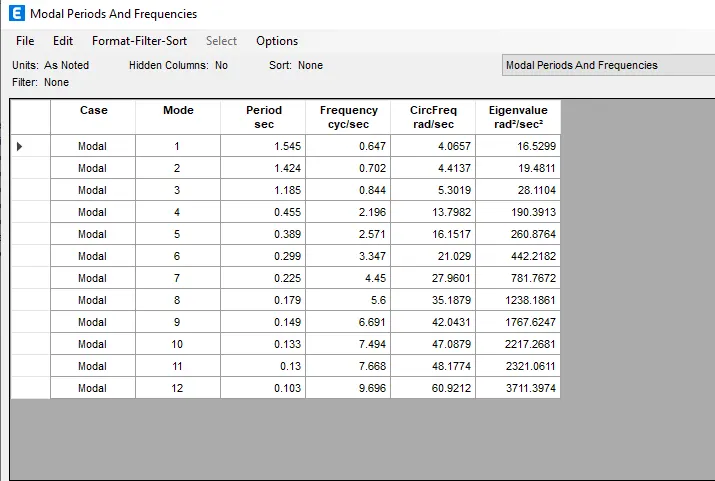
Mode 1 and Mode 2 are differed by less than 10%
1.54 and 1.42
1.54,1.42 and 1.18
And the first three contribute more than 65% Achieved
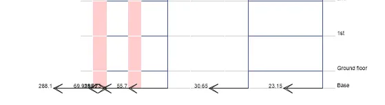
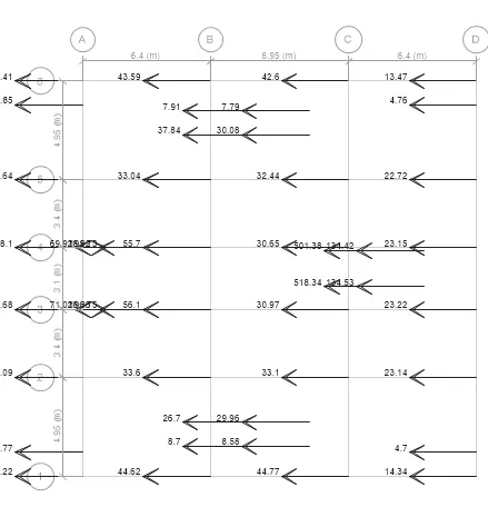
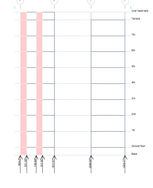
Reactions in shear wall
Reactions in the X directions and Y directions at all the shear walls
-4+14-24+289+288-23-4+13 = 549
288-28-69+195-30+55 = 411
960 x 2
2000 approximately
But the base shear is 3226 means shear wall is taking 61% of total load
Then it is classified as dual type building
Axial load ratio
2000x1000/400x600
Thrn divide by the grade of concrete as 25
We get 33% which is less than 40% achieved