Structural Modelling using Etabs 2018
AIM:Structural Modelling using Etabs 2018
Introduction:
The architectural drawings for a G+7 residential building in zone 5 has been provided. The floor plan is the same for all 7 floor levels. Possible column positions have also been provided. Conceptualize a framing plan layout and then model the building in Etabs. The following architectural drawings have been provided:
- Typical floor plan – The location and thickness of the brick walls and the use of the
space (for estimating live load) can be obtained from this plan - A building section through the staircase and lift core is provided
- Parking layout in the ground floor – the column/shear wall arrangement must not
obstruct entry/exit of vehicles.
The following loadings are to be taken into account: - Brickwall made of AAC blocks
- Finishes – floor tiles of 75 mm thickness
- Live loads as per IS 875 part 2
- Water tank of 20 KL above the staircase at Mumty level
- Lift Machine room at mumty level above lift core
Procedure:
The Above mentioned Project is done as per Is 1893 Part-1 2016 the following procedure is as follows,
Step-1
- Open E-tab Software and Select a new file and save the project as Challange 6
Step-2
- Now the is step is to set the Model initialization.
- Select the built in option.
- In which select unit as metric SI.
- Steel section database as Indian.
- Steel Design code as IS 800 2007.
- Concrete Design code as Is 456 2000 and press ok as shown below.
Step-3
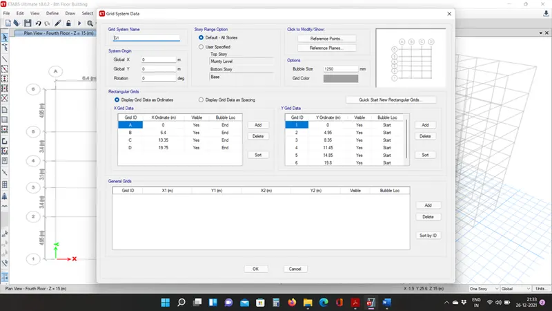
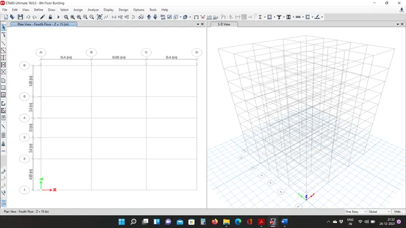
- Now Giving the Spacings of Grids.
- Select grid only option and press ok.
- Now select display grid data as spacing.
- and provide spacing of 6.4m in x direction and 6.4m in y direction.
- 5 grids along x and 4 grids along y as mensioned in question.
- As shown below.
Step-4
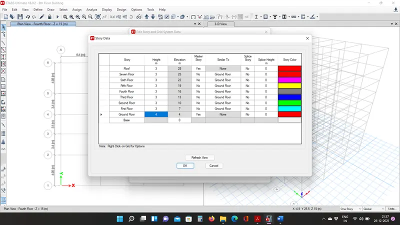
- Select the Storey Data and input the data as mensioned.
- That is select 9 story that is Plinth level and 8 Floors and Roof.
- With 1st floor as master storey and remaining 8 floors as its copy as shown below.
- After completely renaming the Storey press ok.
- Now the model will appear as shown below.
Step-4
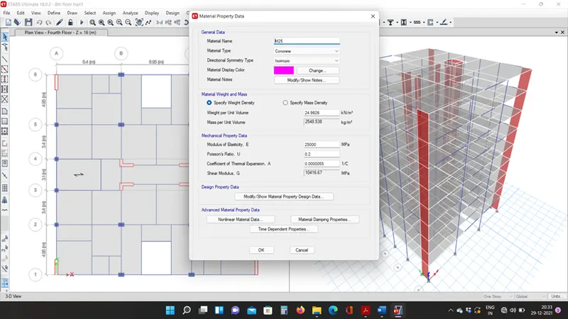
- Now its time to define the materials Properties
- Select concrete as Indian and M30 grade.
- For steel select Rebars Indian ie HYSD 415 grade.
- After completing Selct ok as shown Below.
Step-5
- Now give Section Properties for Column, Beam and Slab ie.,
- For Column select size as 400x400mm
- For Beam 300x550mm
- And For Slab 115mm thk.
-

Step-6
- Now placing of Columns and Beams is done.
- select the quick column option and select Column C1 i.e., 400x400 and place it where required.
- Simillarly select quick beam and select the grids where beams are required.
- and also select quick slab selection and place the slab of given size i.e., 115mm thk.
- And Must be noted that the all storeys option should be selected.
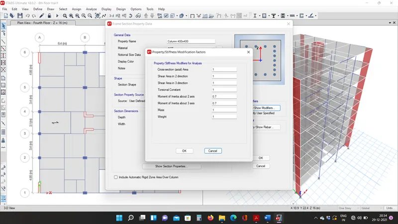
- This is how it will appear after assigning the materials to the grids.
Step-7
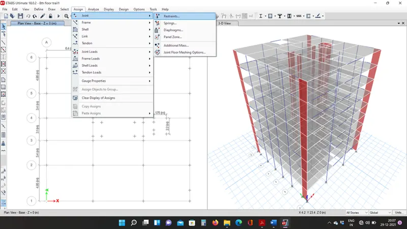
- Now its time to assign the Supports whether fixed or hinge or pined
- In this case hinge support is given that is restricted along x and y only.
- it is done by selecting the points from base plan and assigning the hinge support as shown below.
Step-8
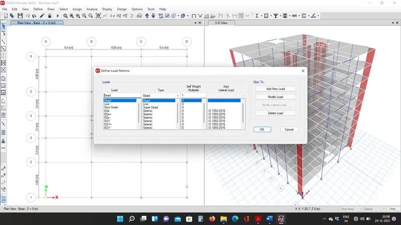
- Defining of loads acting on the building that is
- Dead load, live Load, Wall Load, and Earthquake load.
- For Earthquake load There loads are given those are EQ in X, EQ in X+, EQ in X- and EQ in Y, EQ in Y+ and EQ in Y-
- As shown below.
Step-9
- Now Its time to assign the loads where ever acting
- Select the shell load option and assign the shell load of 3kN/m2 ton each slabs.
- and by selecting distributed load option and giving 10kN/m to all the beams placing between the column as shown below.
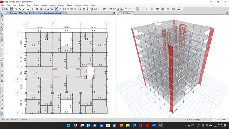
- To Check whwther the loads are propery placed use Perspective Toggle option.
Step-10
- Now its time to assign the load combinations
- As in etabs Load combination is alreay defined just to select proper load combination
- and press okay to assing as shown below
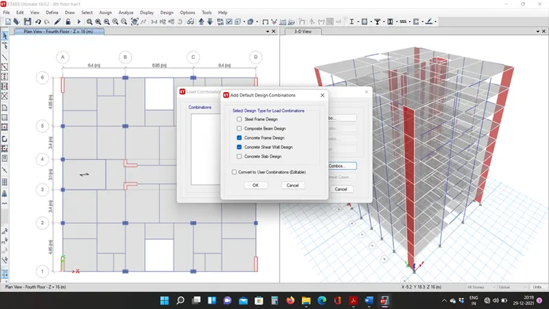
Step-11
- Now Assign the Diaphagram in the sloabs.
- as it is important to set the center gravity of structure as shown below
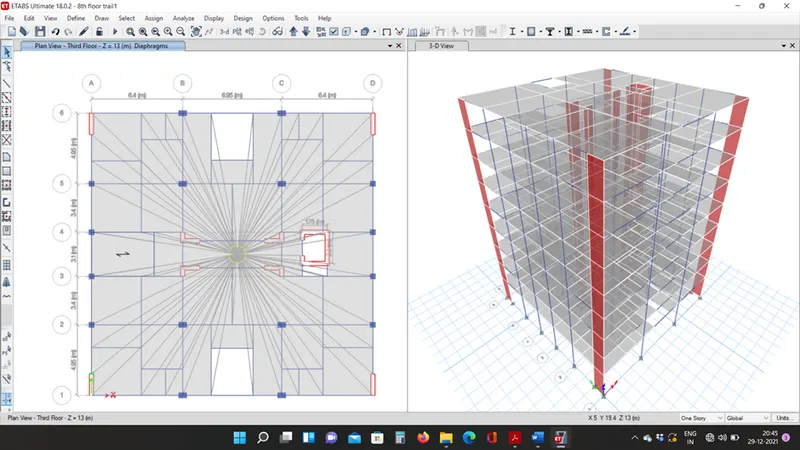
Step-12
- Now Assign the mass sorce data and modal case data
- so that select the assign option and select modal sorce data
- and along with that select modal case data and assign to the structure.
- As shown below.,
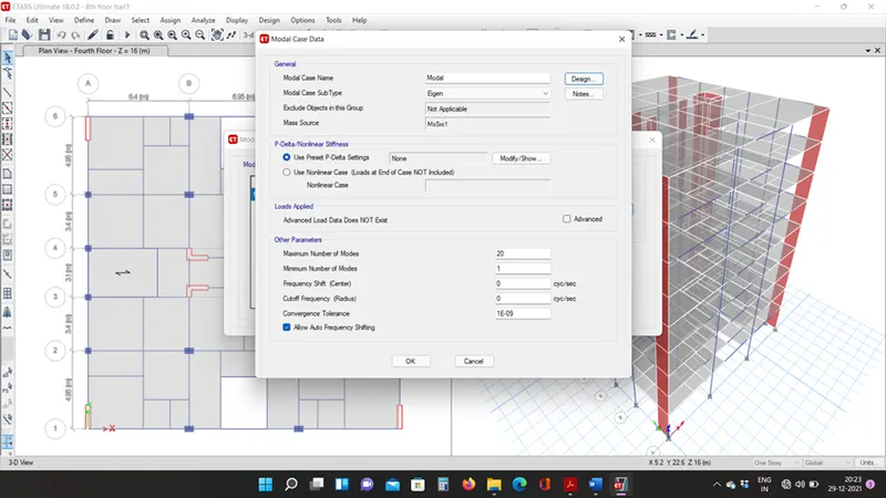
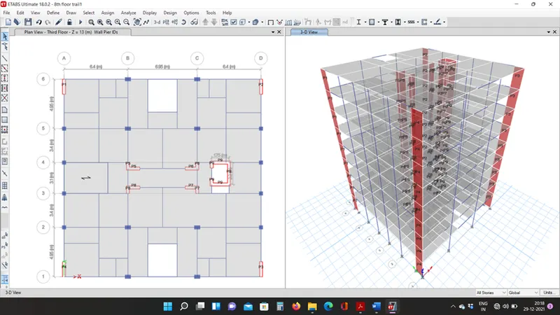
Step-12
- Now the last step is to annalyze whether the structure is free from errors or not
- So select the analyze option and check all the options as shown
- and wait for the message to display as shown below,
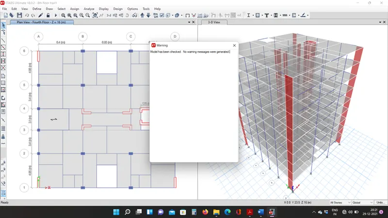
RESULT:
The structural model must comply with provisions of IS 1893 and IS 13920.
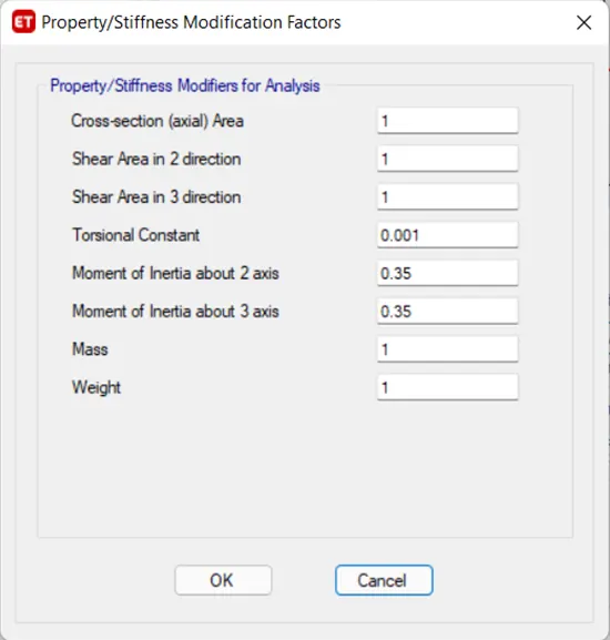
Run a modal response spectrum analysis and check analysis results of the etabs model for inter-storey drift requirements, vertical & planar irregularities, minimum shear wall requirements,maximum axial load ratio for column and shear walls, effective moment of inertia for beams
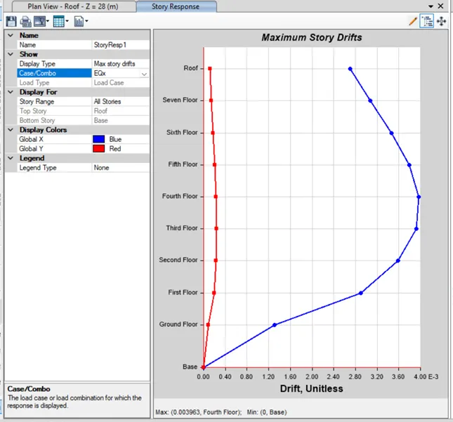
- In the x dirction as per graph the value lies between 4 hence it is acceptable in x direction,
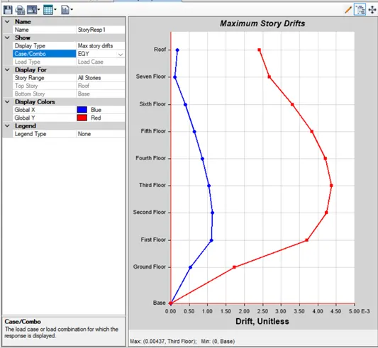
- In the Y dirction as per graph the value lies between 4.5 hence it is not acceptable in y direction,
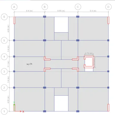
From the above figure it is observed that the building is symmetrical as the area of walls in x direction and y direction is almost simillar.
Effective moment of inertia for beams