Creating a Floor plan, Footing detail and Isometric view using AutoCad
AIM: Creating a Floor Plan, Footing Detail and Isometric view of Steps and Gable Wall in Autocad.
Introduction: Autocad is a drafting software which is used to draft the drawings in present case We are using autocad to create various drawings using different tools in autocad (2019) like Line , pline, rectangle, fillet, champer, etc and along with that isometric drawings using specific commonds and tools.
Procedure:
Selecting of Tools:
Line: Ribbon< Home< Line, Command: Line or L, Home< Draw< Line.
Polyline: Ribbon< Home< Polyine, Command: polyline or pl, Home< Draw< polyline.
Rectangle: Ribbon< Home< rectangle, Command: rectangle or rec, Home< Draw< rectangle.
Ploygon: Ribbon< Home< Ploygon, Command: Ploygon or pol, Home< Draw< Ploygon.
Circle: Ribbon< Home< Circle, Command: Circle or C, Home< Draw< Circle.
Fillet: Ribbon< Home< Fillet, Command: Fillet or F, Home< modify< Fillet.
Chamfer: Ribbon< Home< Chamfer, Command: Chamfer or cha, Home< modify<Chamfer.
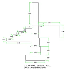
1> Cross Section of Load Bearing Wall over spread Footing:
Procedure:
- Selection of Rectangle tool and select a starting point as 0,0(optional) and select Dimention and type 0.9and 0.25 then touch in display in what dierction u want.
- Select rectangle again and do simillar as above but but give different dimension 0.5 x0.4 rec-1, 0.4 x 0.4 Rec-2, 0.3 x 0.6 Rec-3 , 0.3x0.05 Rec-4, 0.3x1 rec -5.
- keep moving all rectangle sequentially one above the other by taking mid point as refrence point.it forms a pyramid.
- take line and select the point intersecting rec 2 and 3 and give coordinate (@-1.15,0), (@0,0.15), and @1.15,0)
- selct a point and take line and type (@0.3,0),(@0,0.15),(@0.3,0) and end
- Select the Step and copy it amd select base point and muliple option and type 2 and touch the point.
- This Complete the drawing.
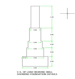
2> Cross Section of Load Bearing Wall Showing Foundation Detail:
Procedure:
- Selection of Rectangle tool and select a starting point as 0,0(optional) and select Dimention and type 0.9and 0.45 then touch in display in what dierction u want.
- Select rectangle again and do simillar as above but but give different dimension 0.5 x0.4 rec-1, 0.4 x 0.3 Rec-2, 0.3 x 0.6 Rec-3 , 0.3x1 Rec-4.
- keep moving all rectangle sequentially one above the other by taking mid point as refrence point.it forms a footing.
- Provide Dimension by selecting dimlinear in commond tab and give it approprietly where ever needed.
- This Complete the drawing.
3> Cross Section of Isolated Footing:
Procedure:
- Selection of Rectangle tool and select a starting point as 0,0(optional) and select Dimention and type 1and 0.4 then touch in display in what dierction u want.
- Select Chamfer and give distance as 0.25and 0.38 and select top left adjacent side. silarly do in opposte sides too.
- Select the offset tool and give a distance as 0.4 and ofset it the bottom line of rectangle.
- Select line and select champer edge and type @0,1.6 and copy that line from base point and copy it to opposite point.
- Select ofset tool and ofset both lines with 0.4 ofset.
- Close that tow lines using line commant at top and ofset it by 0.2 below upto 8 div,
- Provide appropriate dimensions where ever required
- This Complete the drawing.

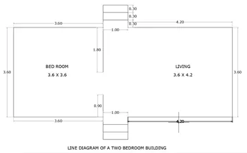
4> Line Diagram of a two Bedroom Building:
Procedure:
- Selection of Polyline command and select any starting point and give coodinat as (@0,-0.9), (@-3.6,0), (@0,3.6), (@3.6,0), (@0,-1.8) and end.
- Again select polyline and select a starting point at top right corner exsisting drawing and select (@0,0.9), (@1,0), (@0,-0.9), (@4.2,0), (@0,-3.6), (@-4.2,0), (@0,-0.9), (@-1,0), (@0,0.9) enter.
- Select complete drawing and explode it by giving command X
- Select the stair portion line and offset by 0.3 as much as required
- Select Mtext coomand and type bedroom 3.6x3.6 and living 4.2x3.6
- This Complete the drawing.
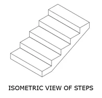
5> Isometric view of steps.
Procedure:
- Type ds (drafting setting) in command and check the isometric view option
- Select line option and start draging line in required direction and with the help of F5 ( function key) for different directions
- Take a line and drag it a required direction and give a magnitude of 1 unit, 0.15 unit and create a rectangle again select a line command and give a magnitude 0.3 in required direction.
- Copy that line to opposite side and join
- Select the complete drawing and copy it by 4 steps and join the bottom line
- This Complete the drawing.
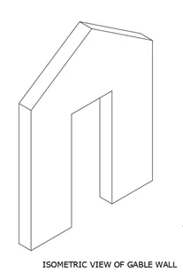
6> Isometric view of Gable wall
Procedure:
- Type ds (drafting setting) in command and check the isometric view option
- Select line option and start draging line in required direction and with the help of F5 ( function key) for different directions
- Take a line and drag it a required direction and give a magnitude of 0.3 unit in z dierection and 3 unit at y direction and 0.3 in -z and 3 in -y.
- select the upper point and draw a line of 3 unit in x and 3 unit in -y and 3 unit in -x and end.
- Select a mid point at upper line and draw a line of 1 unit and enter.
- copy the 0.3 wide line to mid line and at last line.
- join the edges of line.
- This Complete the drawing.
----------------------------------------------------------------------------------------------------------------------------------------------------
END