Structural Modelling using Etabs 2018
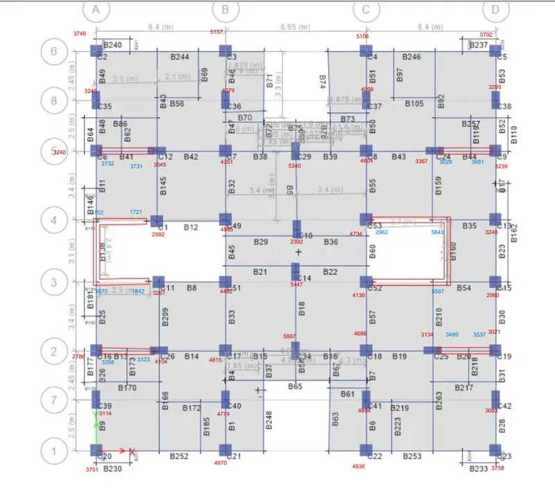
Axial Force ( Fz )
In Above Layout plan, labelling is done through two colours which represent Fz (Axial Force) in a column :
Red Colour represent Fz under the Column while Blue colour represent the axial force in KN under Shear Wall.
For Detailed inspection, its PDF is attached here under.
INTRODUCTION:
Above plan has two types of Column whose properties are represented here under:
| Section | Longitudinal R/F | Hoop R/f | |
| 600*600 | M50 | 25dia at corner, 20 remaining(Fe 550) | 10mm Dia (Fe 415) |
| 400*600 | M50 | 25dia at corner, 20 remaining(Fe 550) | 10mm Dia (Fe 415) |
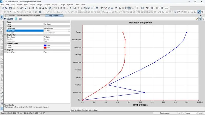
Due to Soft storey mechanism, there are two kinks in Storey Drift along X axis due to (UDcon2 enclosing 1.5 DL +1.5LL)
though the results are coming under the critical limit of 0.4%H.
=========================================================================
This layout plan belongs to Structural Wall System as enclosing more than 90% of Lateral Loads acting over the building.
| EQx | Resist by Frame | By Shear Wall | Total Load | % Shear Resist By Frame | Comment |
| Fx | 560 | 9100 | 9710 | 5.76 | <25%; Structural Wall System |
| Fy | 10 | 9610 | 9710 |
For Validation, Model are attached named as Challenge 10Seismic.
| EQy | By Frame | By Shear Wall | Total Load | % Shear Resist by Frame |
| Fy | 492 | 9100 | 9710 | 5% |
| Fx | -8 | 7 | -1 |
Response Reduction Factor to be adopted as 4 ( Structural Wall System).
Zonal factor 5th (0.36)
Soil condition: Soil 1st, hard & Rocky strata.
Importance Factor=1.2; For more than 200 occupants
=========================================================================
Shear wall Area comes out to be 2.14% whose representation comes under:
| Length | Thickness | Total Area | Floor Area | |
| W1 | 2.5 | 0.3 | 20*20 | |
| W2 | 2.5 | 0.3 | ||
| W3 | 2.5 | 0.3 | ||
| W12 | 2.5 | 0.3 | ||
| W14 | 2.5 | 0.3 | ||
| W21 | 3 | 0.3 | = 8.55/(20*20) | |
| W22 | 2.5 | 0.3 | =2.14% | |
| W24 | 3.1 | 0.3 | ||
| W26 | 3.7 | 0.3 | ||
| W27 | 3.7 | 0.3 | ||
| Summation | 28.5 m | 8.55 m^2 |
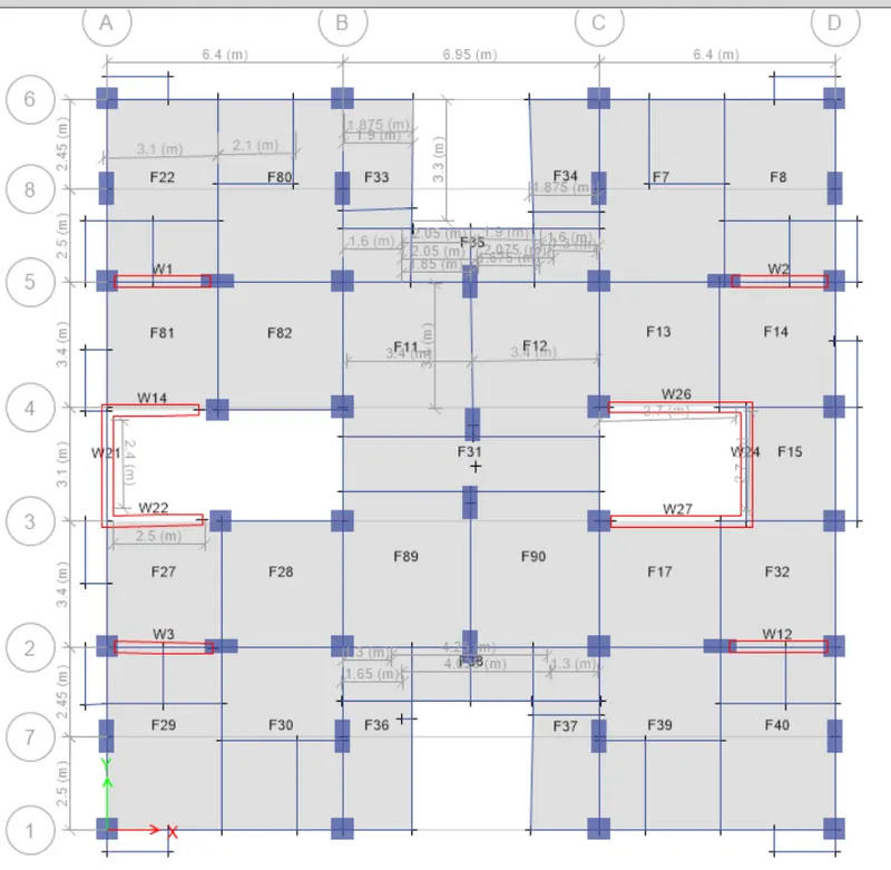
By adopting 2.14% shearwall Area, we can resist more than 90% of Lateral Load coming over the Prototype.
==========================================================================
Virtues to be noted:
1. Very less probability of Differential Settlement as along the specific grid, there is hardly 10% variation in Fz(Axial Load.
2. Even After reaching the Ultimate State, we have quite some relaxation to reach 0.4fck in crucial columns.
(shape Factor (1.15-1.2) for crucial member)
3. Provision of less than 0.4% of Interstorey drift should be achieved at serviceability load combination but here, Even after Taking the Ultimate Load combination, We are not crossing the above limit.
4. Lateral loads are mostly accumulated at the central portion between 2nd & 5th Grid as per our Layout Plan, resulting insignificant effect of open storey at the Ground Floor.
5. Columns on either side of (2nd & 5th Grid) portion, would have not been coming under Tension Zone.
6. First Two Translational Modes of Natural Period Should be greater than Torsional Mode of Natural Period as described in attached screenshot below:
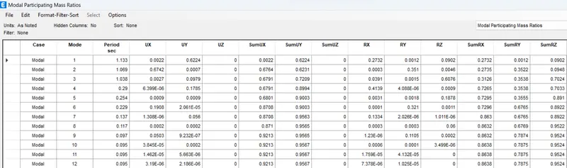
7. 10% of Fundamental Natural Period Difference among the Ist three period mode of Vibration is not achieved.
8. Due To Open Storey at Ground Floor, we have to design the column for the action force of 6500 KN which can be purged out to 4300 KN with ExtraOrdinary Load distribution under all the Columns.
I have attached an Ideal Layout Plan(PDF Form) as per my understanding which can mitigate all the possibility of erratic behaviour of building during its Serviceability Period.