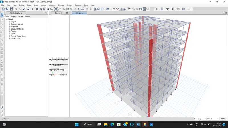
Structural Modelling using Etabs 2018
Q1). The architectural drawings for a G+7 residential building in zone 5 has been provided. The floor plan is the same for all 7 floor levels. Possible column positions have also been provided. Conceptualize a framing plan layout and then model the building in Etabs. The following architectural drawings have been provided:
- Typical floor plan – The location and thickness of the brick walls and the use of the
space (for estimating live load) can be obtained from this plan - A building section through the staircase and lift core is provided
- Parking layout in the ground floor – the column/shear wall arrangement must not
obstruct entry/exit of vehicles.
The following loadings are to be taken into account: - Brickwall made of AAC blocks
- Finishes – floor tiles of 75 mm thickness
- Live loads as per IS 875 part 2
- Water tank of 20 KL above the staircase at Mumty level
- Lift Machine room at mumty level above lift core
The structural model must comply with provisions of IS 1893 and IS 13920.
Run a modal response spectrum analysis and check analysis results of the etabs model for inter-storey drift requirements, vertical & planar irregularities, minimum shear wall requirements,maximum axial load ratio for column and shear walls, effective moment of inertia for beams
and columns etc.
AIM :
To model and analyze the G+7 residential building in zone 5 from the given architectural drawings using the ETABS 19.
INTRODUCTION :
ETABS is an engineering software which is used to design multi-story building analysis and design. Modeling tools and templates, code-based load prescriptions, analysis methods and solution techniques, all coordinate with the grid-like geometry are all the features of this Etabs software.
PROCEDURE :
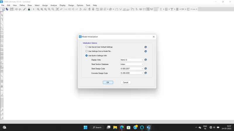
- Open Etabs software and go to File then New model then click on that.
- Hence new model page will open then select Use built in settings and provide the data displayed in the screenshot attached then click ok.
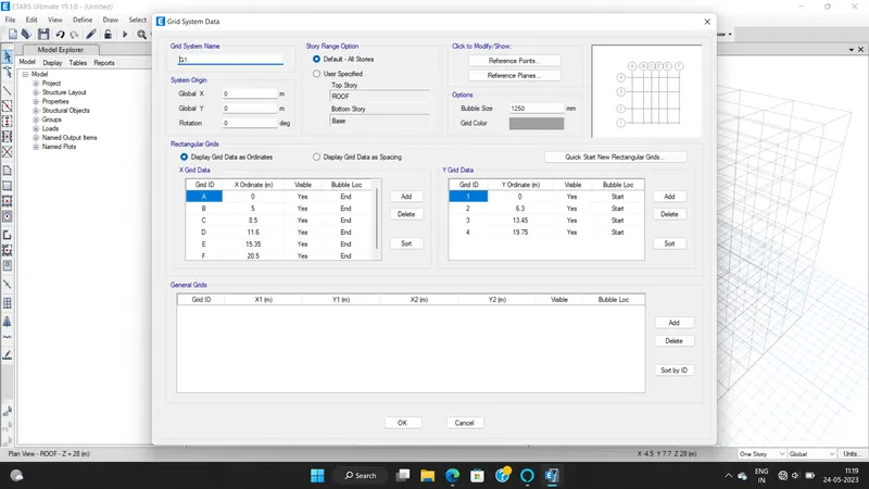
- After that Grid system data dailog box will open .Provide the grids as shown in attached picture.
- Then click ok.
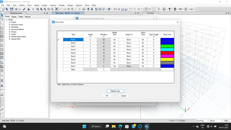
- Enter the story details as per mentioned in the question.Make story 1 as master story and other stories similiar to story 1.
- Then click ok to proceed.
- Now you can see the model has been created as a grid system as per data entered.
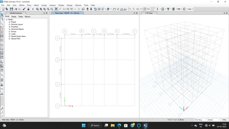
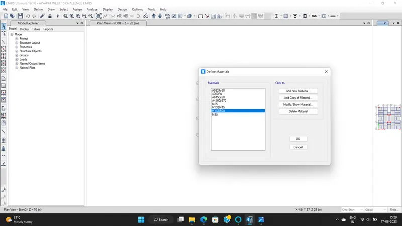
- Go to Define then Materials to create materials required for the model.
- A dailog box will open ,click on the Add new material and enter the details of the required materials.
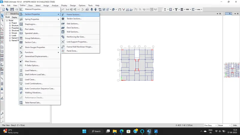
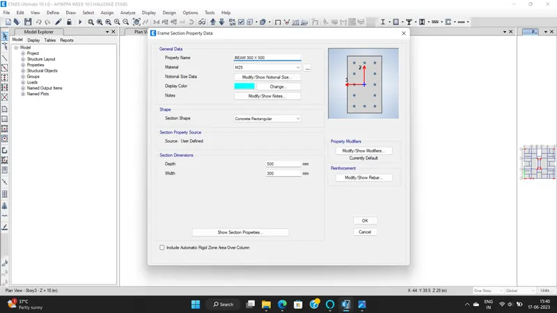
- Then go to Define again then Section properties then Frame sections to add the frames for the model.
- Create a new frame and name it as per data required. For beams select the M3 Design option and define the rebar material as Longi.bars as HYSD500 and Confinement bars as HYSD415.
- then click ok.
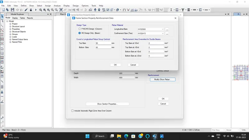
- Similarly do the same steps for columns also.
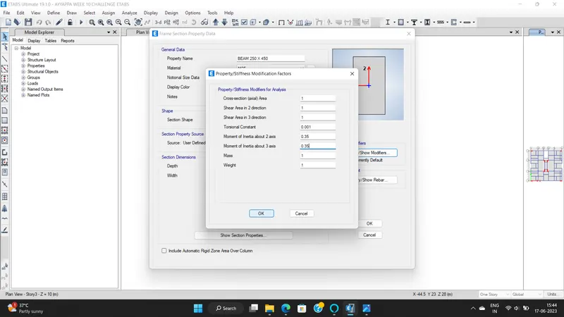
- And then click on the Modify/Show modifiers.
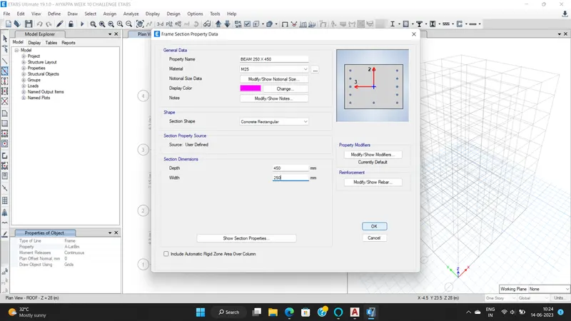
- There provide the Moment of Inertia about 2 and 3 axis as 0.35 and tortional content as 0.001.
- Enter 0.7 value for moment of inertia for column.
- Then click ok.
- For Column select the design type as P-M2-M3 design and assign the longitudinal and confinement bars.
- Then click on Modify/Show rebar and enter moment of inertia value as 0.7 for 2 and 3 axis.
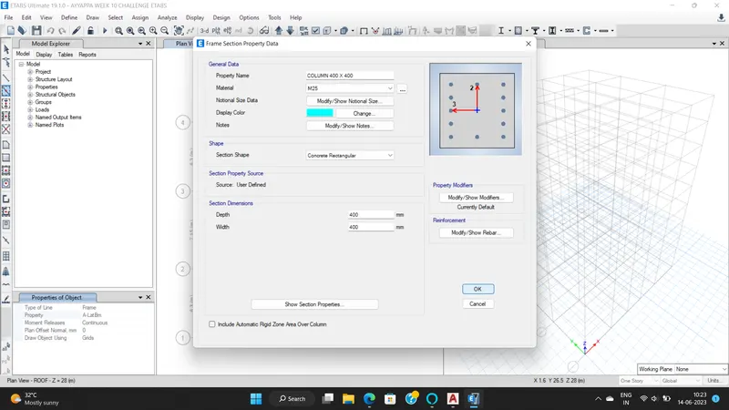
- Do the same step for other columns also.
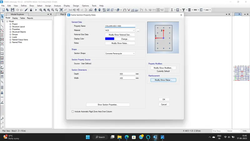
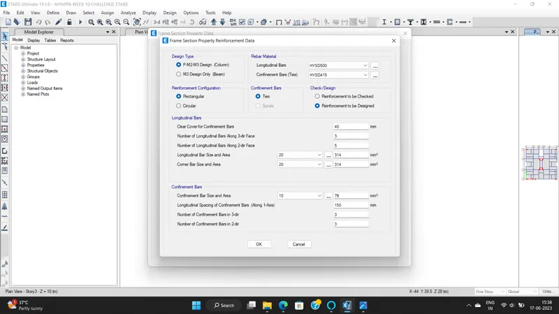
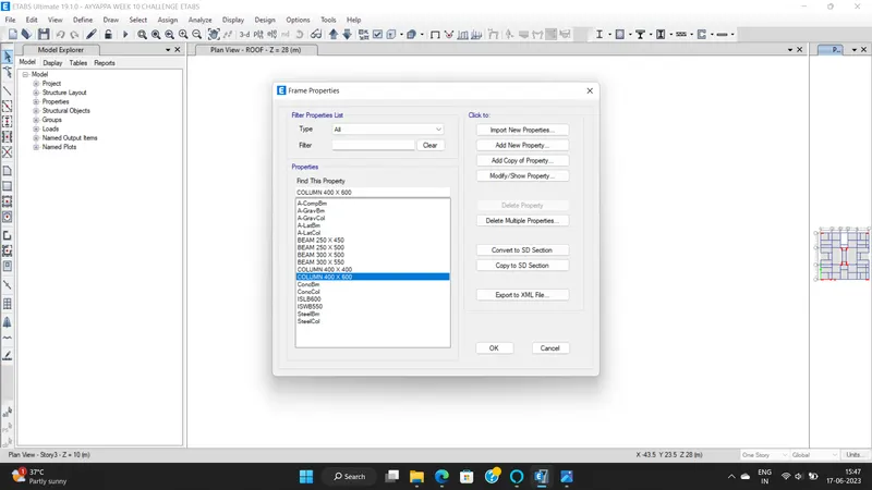
- Now you can see the created frame sections.
- For slab,
- Go to define then section properties then slab sectiions
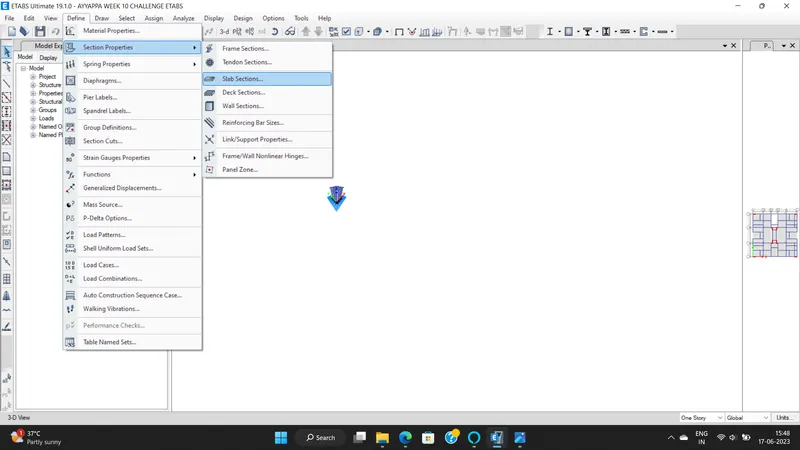
- Add the new slab section and enter the required details as thickness 125mm
- Slab material as M25 them click ok
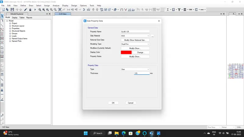
- Also add slab for staircase . Do the same steps and enter thickness as 200mm.
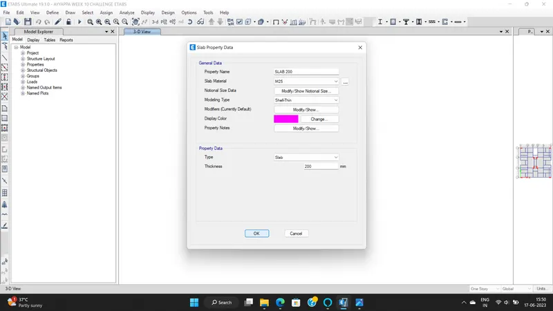
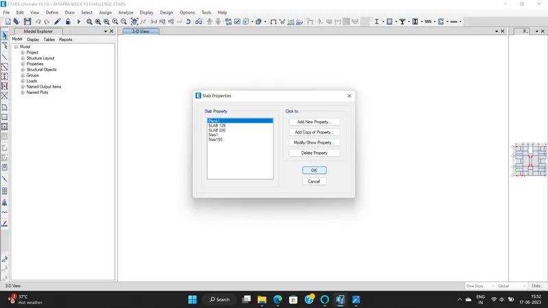
- Now you can see the created slabs.
- click ok.
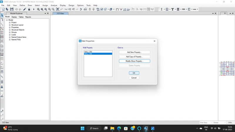
- Then for wall sections
- Go to Define then Section properties then wall sections.
- Enter the details in the dailog box opened.
- wall material as M25
- Modelling type as shell thin then click ok
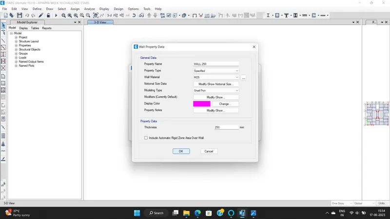
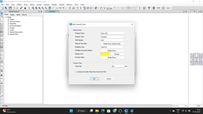
- Hence walls are also added to the model .
- Now to assign the columns
- Click on the Quick draw column option and draw the columns as required
- Select from the properties option and assign the columns
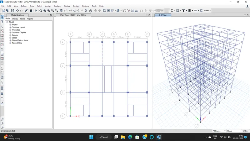
- For beams click on the quick draw option then select the appropriate properties of the beams which are required and then assign the beams in the model.
- Now apply the secondary beams in the model with the help of the plan attachment which is given.Refer to that plan and draw the secondary beams.
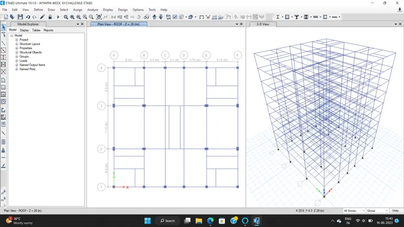
- Now assign the shear walls in the model by clicking on the draw walls option.
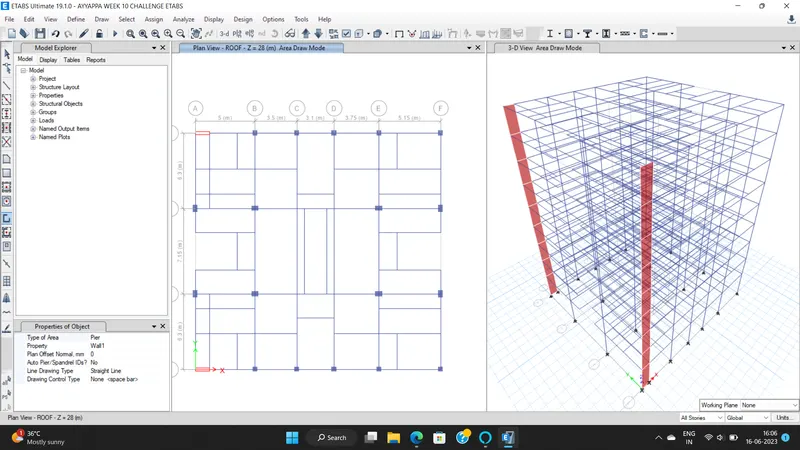
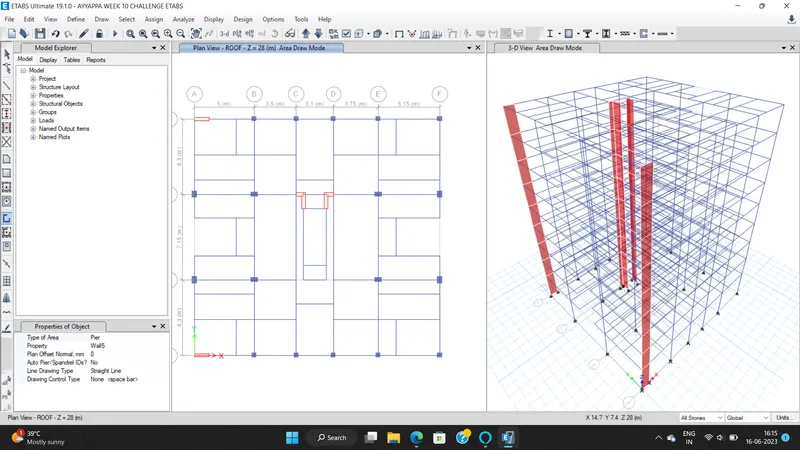
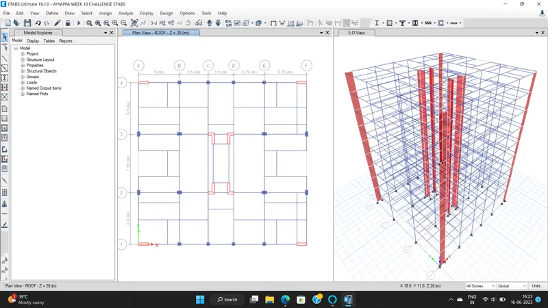
- After shear walls have been assigned ,then assign the slab surface in the model.
- For the stair case area add the STR_slab which we have assigned.
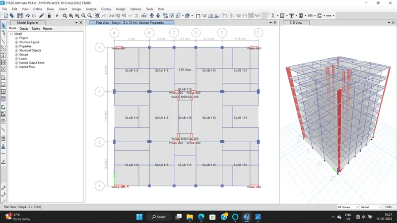
- Now select all the columns that are provided.
- Go to Assign then Joint then retraints to assign fixed support system.
- Then select the fix support form the dailog box and then click ok
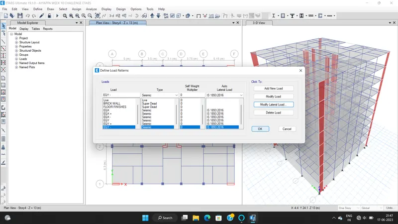
- Then go to define then load patterns .click on that
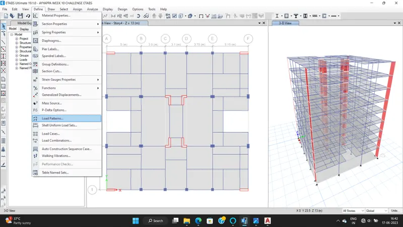
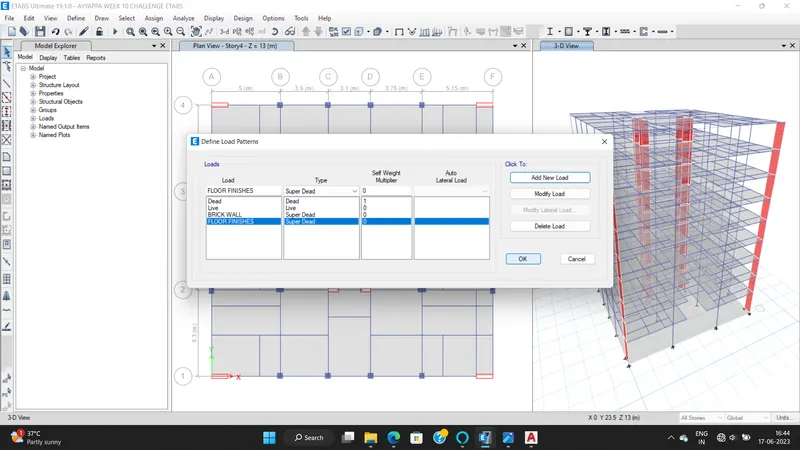
- Then assign the loads as displayed in the attached screenshot
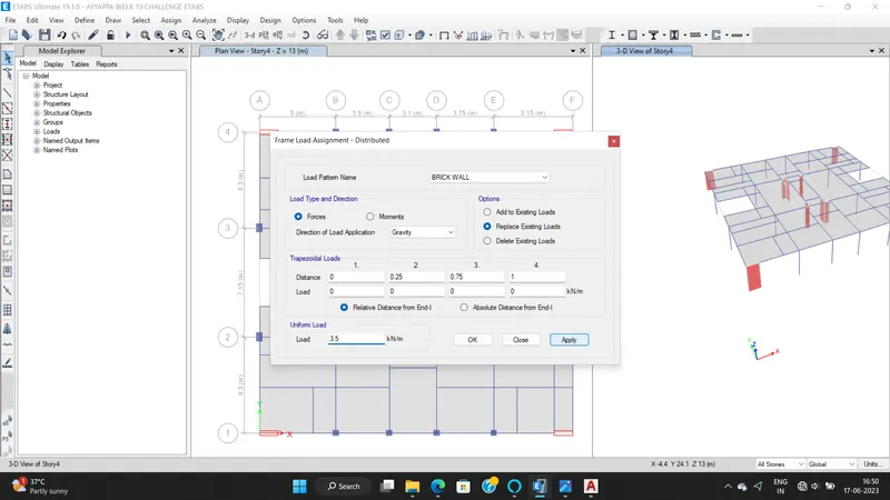
- Then go to Assign then Frame loads then select Distributed.
- Then select the load pattern name as Brick walls and assign uniform load of 3.5kn/m and then click ok.
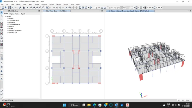
- Hence assignes loads are now visible in the modal.
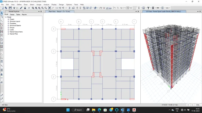
- Then for shell loads
- Go to assign then shell loads then uniform
- Provide load pattern as Live , enter uniform load as 3kn/m for stair and lift area.
- Then click ok.
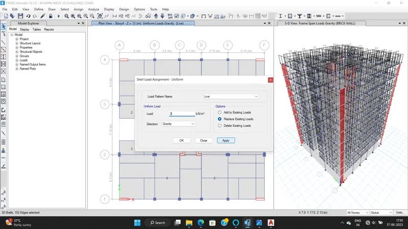
- Provide load pattern as Live , enter uniform load as 2kn/m for other area.
- Then click ok.
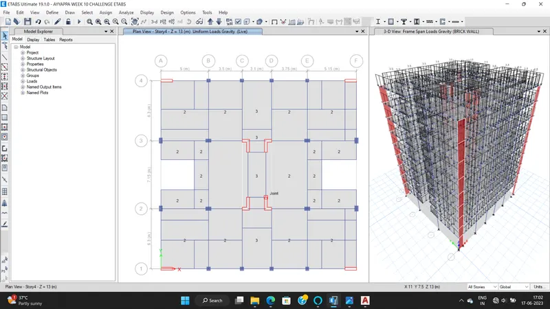
- Hence floor loads are also assigned.
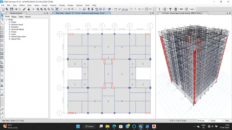
- For reducing liveload by 10% ,
- Go to design then live load reduction factors
- Add the loads as per reduction to be provided.
- Then Click ok.
- To assign the mass source
- Go to Define then click on the mass source
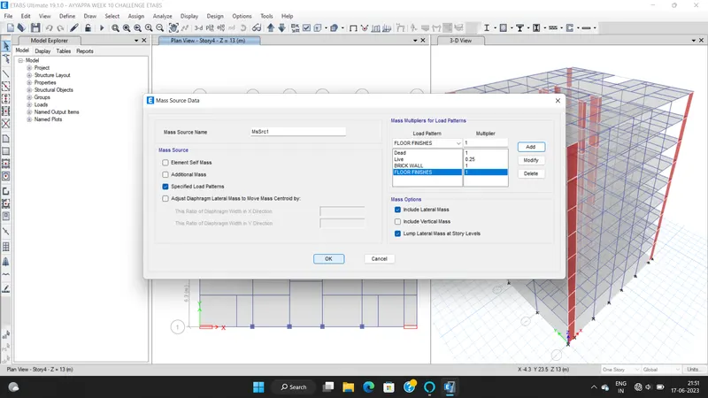
- Add load patterns as per shown in the attached screenshot.
- then click ok .
- Now for the diaphragms assignment
- Go to the Assign option then go to shell then Diaphragms
- Select D1 from the dailog box then click ok to proceed.
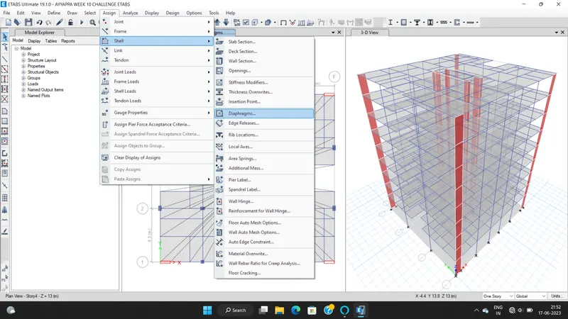

- Hence assigned diaphragm is now visible in the model.
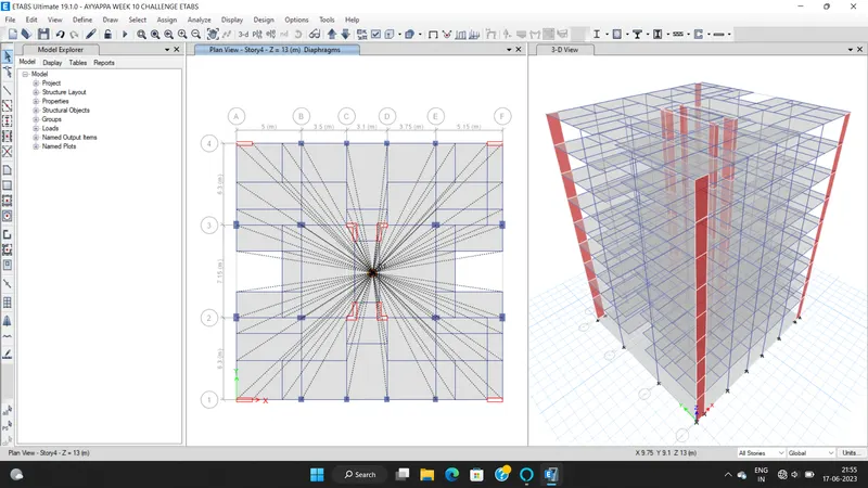
- For assigning pier labels to the shear walls
- Go to Assign then go to shell then pier label.
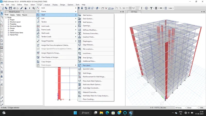
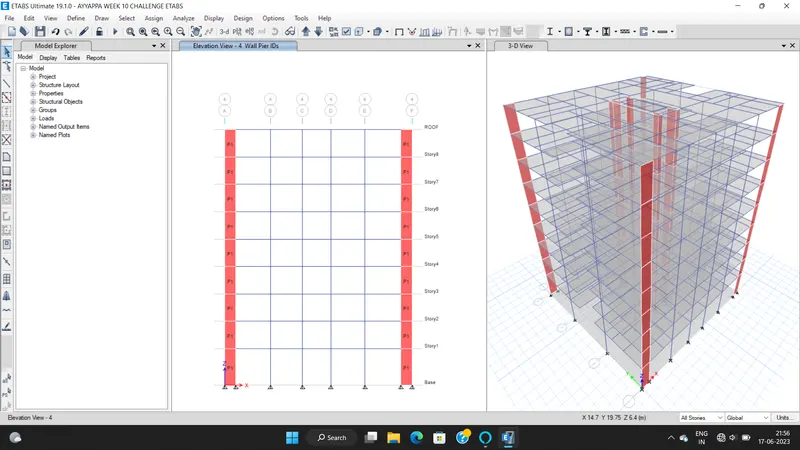
- Add the pier label name first as P1,P2,P3,P4,P5,P6,P7,P8 and then assign the pier label to the different shear walls.
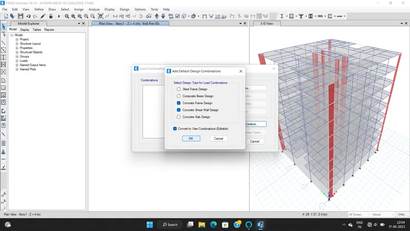
- Now to add load combinations.
- Go to define then click on the load combinations.
- Add the load combination by selecting on the Detail design combinations as concrete frame design and concrete shear wall design.
- Click ok .
- For Response spectrum assignment
- Go to define then Functions then go to response spectrum
- Provide the values and name as in the attached screenshot.
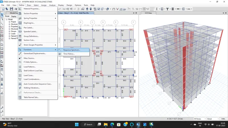
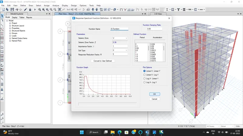
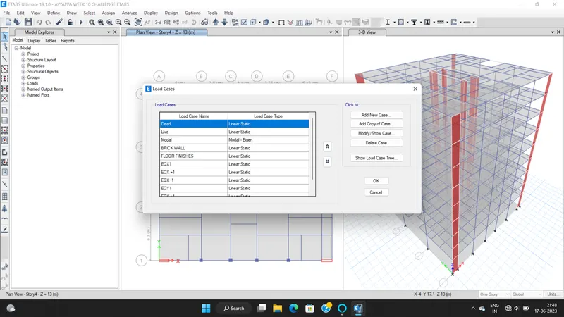
- Then in the load case data tab ,provide first for RSx then do the same for RSy.
- Then Click ok.
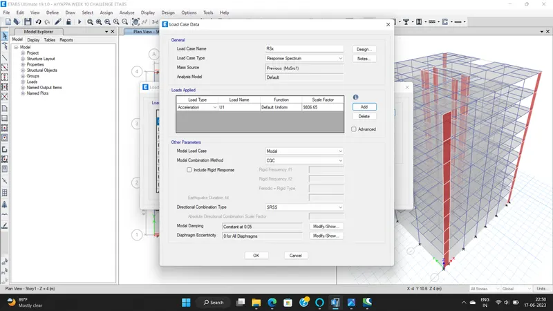
- Finally now run the analysis of the building.
- Before analysis please check the model.
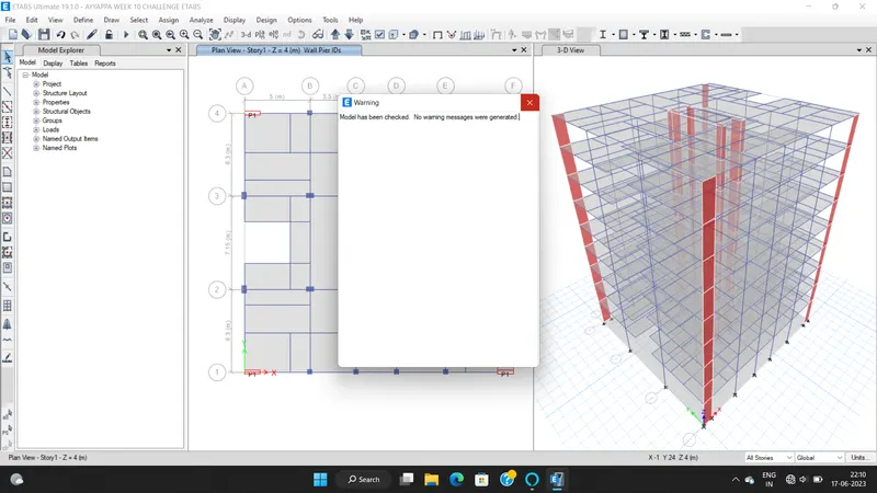
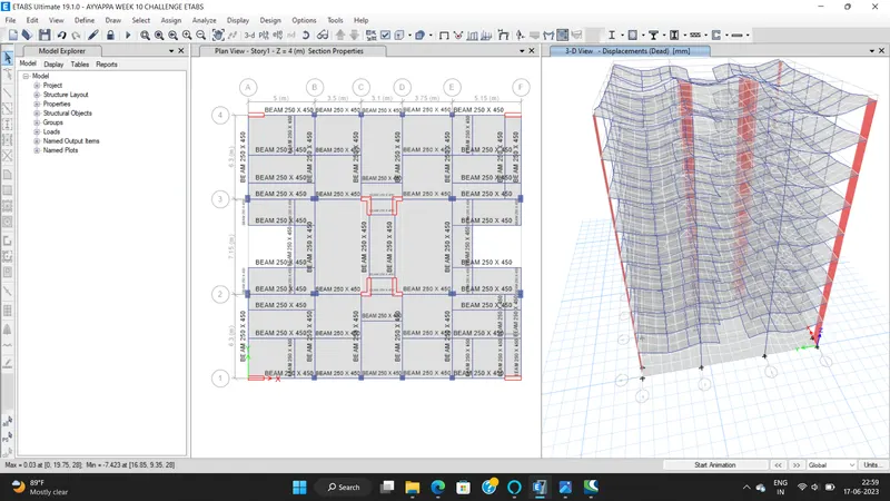
- Deformed shape of building after the analysis done will look like this.
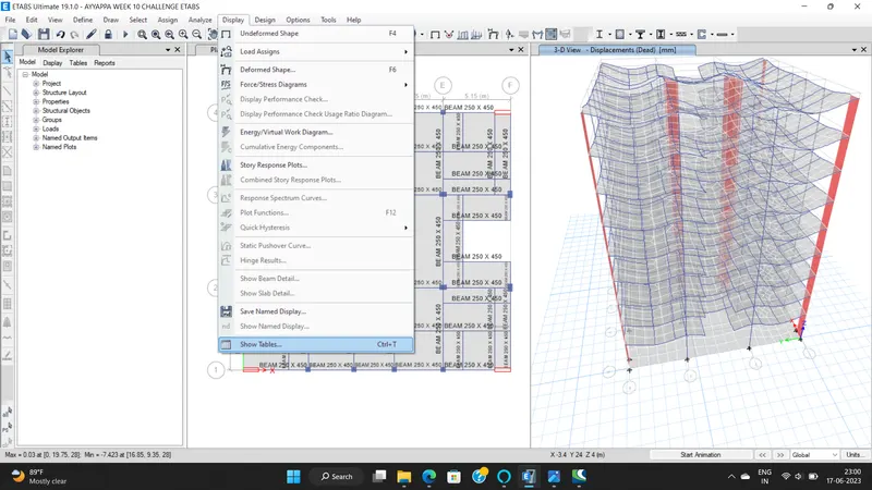
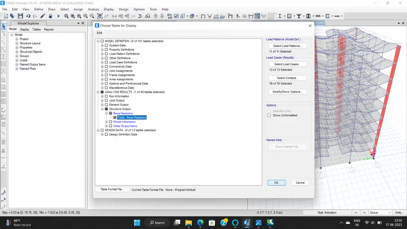
- To see the result of the analysis, Go to display then click on the show tables option.
RESULT :-
Hence the model has been analysed and the following results are achieved for given conditions
- Modal Mass Participation for first 3 modes must be 65%
- Hence achieved.
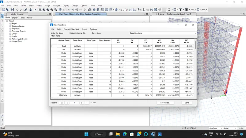
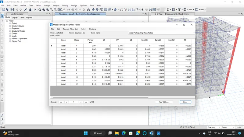
- Mode 1 and 2 differs by 10%
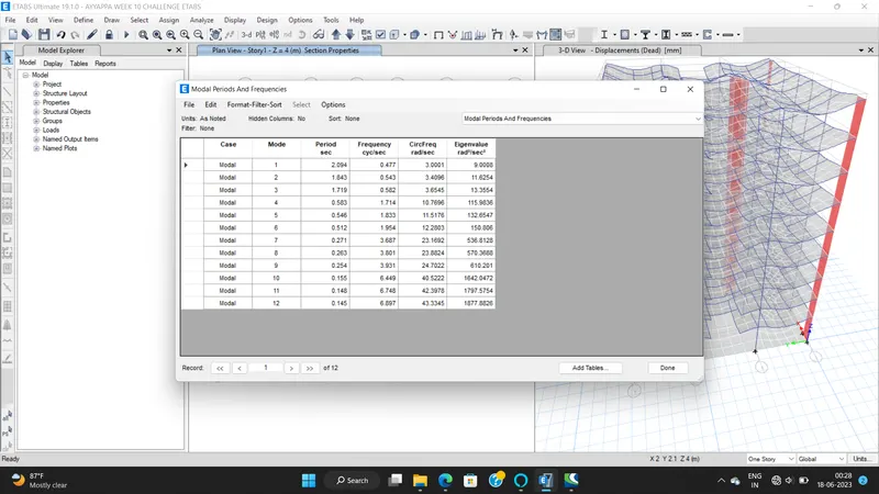
- It is also achieved.
- Principal modes must be greater than Torsional mode.
- Achieved.
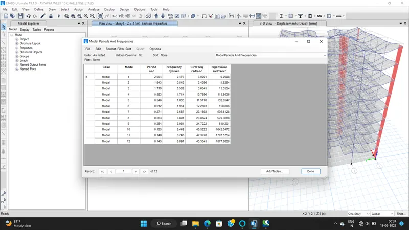
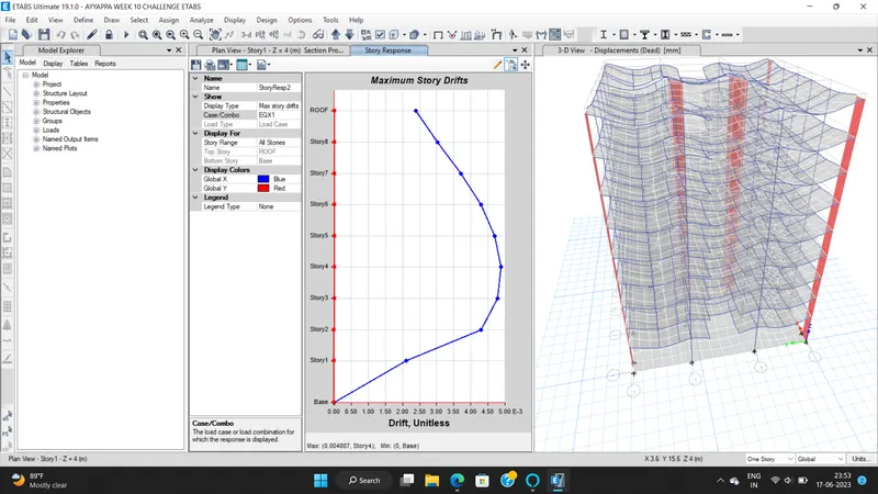
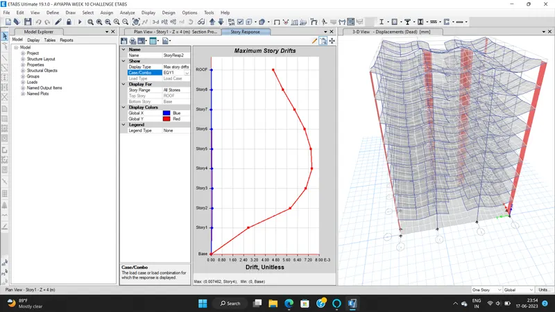
- Inter storey drifts must be limited to 0.004
- ACHIEVED
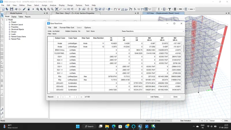
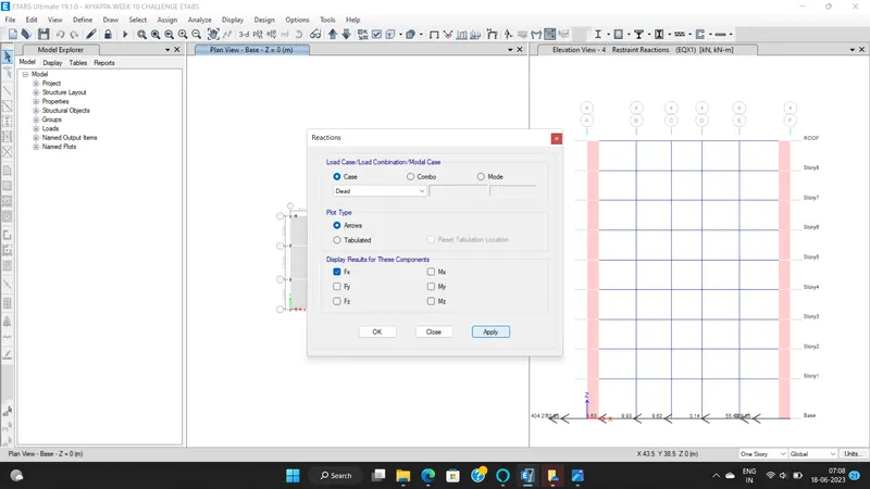
- Now open the reactions tab, then select the eartquake load towards X-direction(EQX) in the load case, then click on ok .
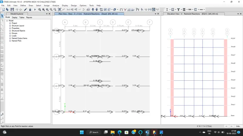
- The base shear reactions are now shown
- When we divide the base shear which is taken by shear wall divided by the total base shear of building , it will get us the % of shear force taken up by the shear wall.
- If it is less than 80%, then more shear walls are need to be added.
- Here in our building it is sufficient.
RESULT :-
The G+7 building has been modelled and analysized succesfully using the E-TAB Software.