Creating Kitchen layout, Hatching of Architectural elements and sectional view of an Industrial Building in AutoCad
Q1.
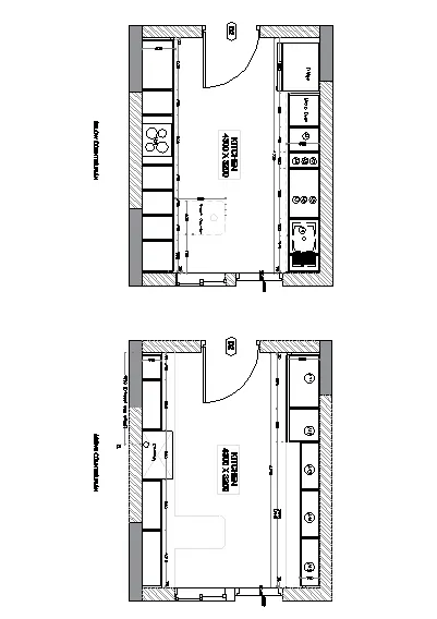
AIM :-Create the layouts of the Kitchen and provide hatches pattern as shown. Also, use blocks wherever required. Provide appropriate dimensions in the plan. Assume the size of doors, appliances and others as per the standards.
COMMANDS USED:-
- Limits command
- X-Line command
- Line command
- Offset command
- Hatch command
- Dimlinear command
- Dimstyle command
- Units command
- Extend command
- Fillet command
- Trim command
- Join commandi
- Line weight command
- Line type command
- Object snap command
- Rectangle command
- Zoom command
PROCEDURE:-
UNITS - Type un for units and set a decimal unit and in milimeters.
layers - creating seperate layers for seperate columns. use green layers for wall. pink for door and windowyellow for own. for hatching use cyan color. for text use orange new roman style.
dimension - for dimension using dimlinear tool.
THE FOLLOWING STEPS WERE USE TO CREATE BELOV COUNTER PLAN.
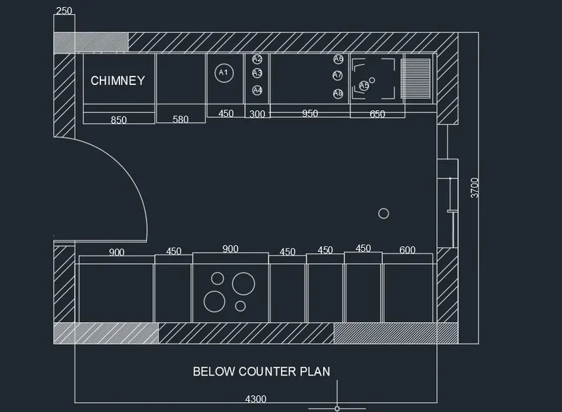
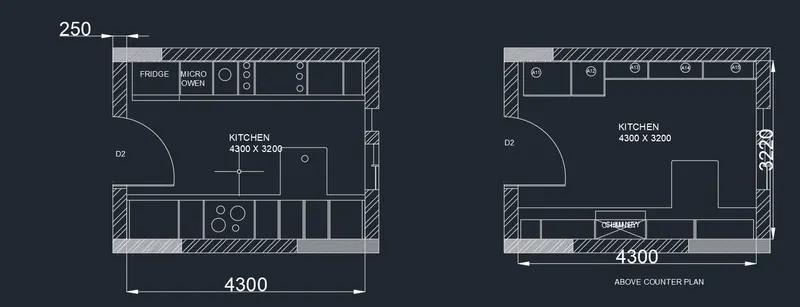
1. create twho x line with respect to x and y direction and take 4300x3200 230mm offset both side.
2. in bottom side of the kitchen creating a kitche platform and hob and taking continusely offset 900,450,900,450,450,450,180,35 in second 900 offset creating hob inside the box. and create a small circle inside the Hob.
3. taking 15mm offset to create a line and above the hob create a small snacks counyter having 600x900 area respect to x and y direction. and make small circle inside the snack counter.
4. in above side of the kitchen create a 1000mm in y direction and make a fridge there.
5. side of the kitchen creating a micro oven 600mm by taking a offset. and continusely taking a offset450, and continuesly taking a offset 315,900,900 to create a platform.Type offset command of size 35, 900, 450, 900, 450, 450, 450, 560, 35 .Draw the hob and place the circle in the hob.
FOR MAKING ANOTHER PLATFORM TAKING CONTINUESLY 35,965,585,868,865,865 AND CREATE A BLOCKS A11,A12,A13,A14,A15.
6. and making a small oven boxe with its own dimension.
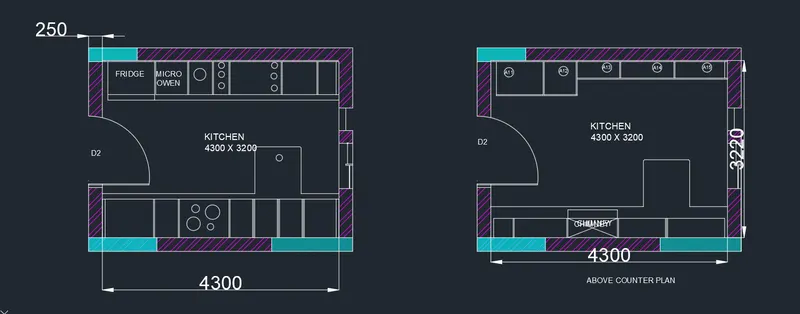
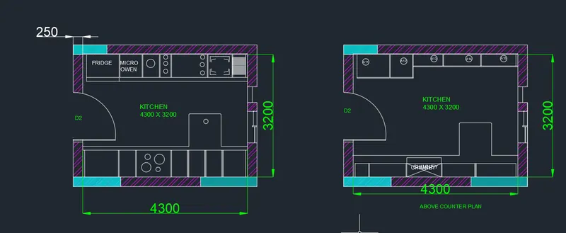
7. providing a 600mm door and 1126mm windows to the kitchen. and providing a hatch in suitable portion.
Hatching of walls
Go to the Draw panel on the Home tab. Find the hatch icon in the bottom right corner.
In "Hatch creation” tab. Go to its Properties panel and choose the Hatch type that you would like to insert. Here pattern type was used for hatching. 8
In hatch settings "create separate hatches" options was selected, so that each entity will remain as an individual if any correction was to be made, else it would have to be done from first.
Pick points options was was to hatch the area. The “Pick Points” will determine a boundary around the specified point.
After filling the area, hit “Enter” to apply the hatch.
RESULT:-
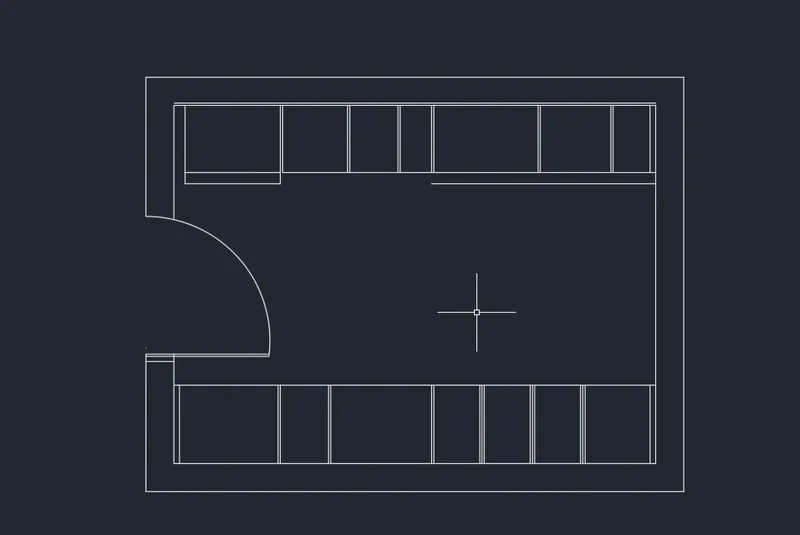
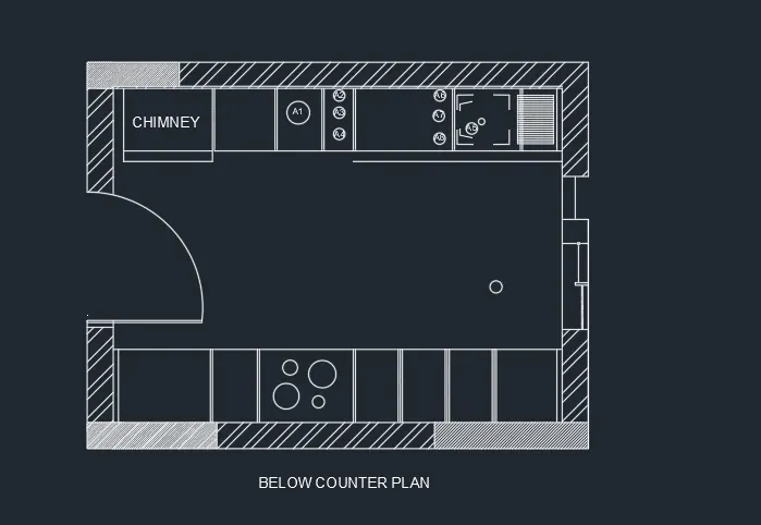
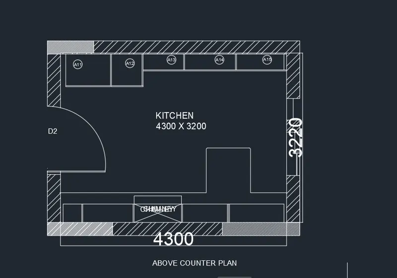
RESULT:-
The layouts of the Kitchen and provide hatches pattern is completed by using autocad.
AIM:-
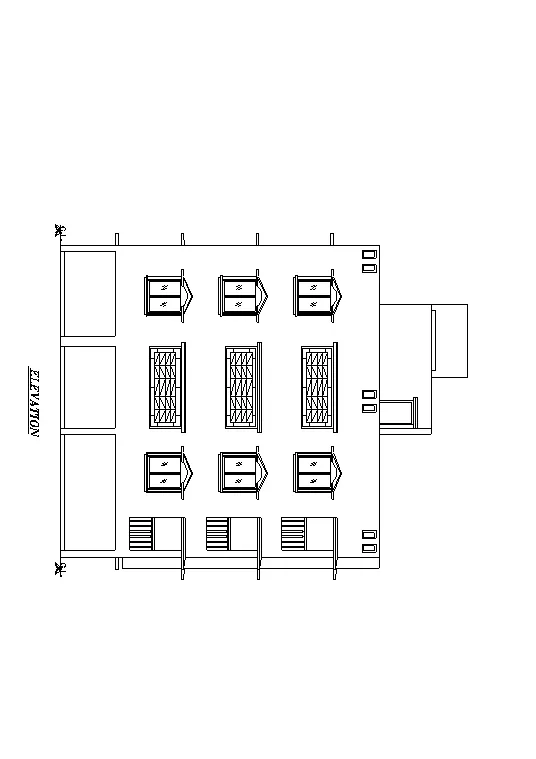
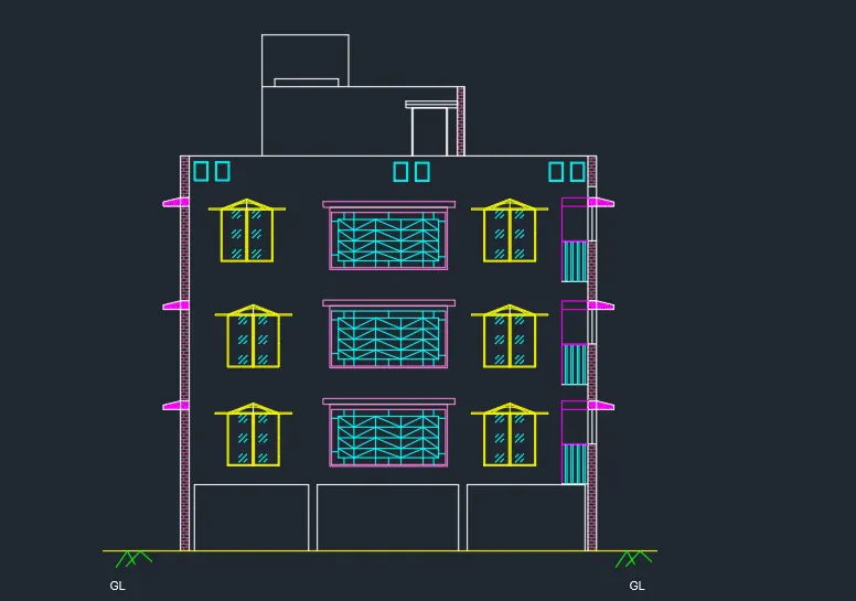
Create the elevation of the plan created in the Challenges 7 and apply proper hatch in the walls, doors, windows, and other architectural elements. Refer to the dimensions in Plans and sections in Challenges 7.
COMMANDS USED:-
- Limits command
- X-Line command
- Line command
- Offset command
- Hatch command
- Dimlinear command
- Dimstyle command
- Units command
- Extend command
- Fillet command
- Trim command
- Join commandi
- Line weight command
- Line type command
- Object snap command
- Rectangle command
- Zoom command
PROCEDURE:-
1. LAYERS - For creating elevation of floor plan created in challenge 7. using multi bylers for hatching use dark red orange and transparent grey color. for creating window using cyan color and window projection using yellow color.
2. UNITS - units alredy saved in challenege 7 who are in decimal in mm.
3. wall attch window - for crearting window taking a rectangle having 1600x1200 and creating a horizontal line in bottom side. inside that line creating a vertical line and giving 200mm offset againg provide 10mm offset.in top side taking am line tool and make window projection in the wall.
4. WINDOW - for creating a window taking a rectangle tool. and create rectangle having size 1200x1100mm and inside the rectangle create a two small rectangle. from it center. in bottom side create a small and having extra leangth to the rectangle from its edge create a verticsl line and create a trangle of two adjoints line. and taking a arc for creating a haif circle and strech it by its point. and hatching inside by ANSI31 and copiying five object of window
5. WALL - WALL projection is made by its refrence and hatching by ANSI32 brick for hatching using dark orange color and fillig grey color by low transperancy.and hatching the all wall as shown in figure.
6. MID SIDE ELEVATION - between both window create a projectoion mid elevattion taking a rectangle having 4000x1330mm size. and abow that rectangle create an another rectangle. after creting another rectangle inside the big rectangle and hatching inside the rectangle. by net wired frame.
7. DIMENSIONS - for providing a dimension using dimlinear and after that taking dimcontinue tool for continues dimension.
8. OVER HEAD WATER TANK - FOR creating over head water tank taking a rectangle tool and create 2400x1200 over head water tank in top of the elevation. and its bottom use hatching having greay garediant.
9. TEXT - For creating text using multiline text and change multiline text by new roman and use bolded charecter for adding a text.
10. BEAM - For showing a beam create a small rectangle top of the elevation and provide offset 10mm outside of the rectangle.
11.HATCH:- Use the HATCH Command to show hatch in the drawing.
Hatching of walls
Go to the Draw panel on the Home tab. Find the hatch icon in the bottom right corner.
In "Hatch creation” tab. Go to its Properties panel and choose the Hatch type that you would like to insert. Here pattern type was used for hatching. 8
In hatch settings "create separate hatches" options was selected, so that each entity will remain as an individual if any correction was to be made, else it would have to be done from first.
Pick points options was was to hatch the area. The “Pick Points” will determine a boundary around the specified point.
After filling the area, hit “Enter” to apply the hatch.
A new layer is now created, named as texts and a suitable colour is selected and this layer is made as the default.
Now using the MTEXT all the texts was made and the following image is obtained.
A new layer is now created, named as Dimensions and a suitable colour is selected and this layer is made as the default.
Now using the Dimlin the dimensions was plotted and the following image is obtained
RESULT:-
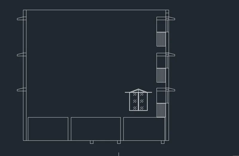
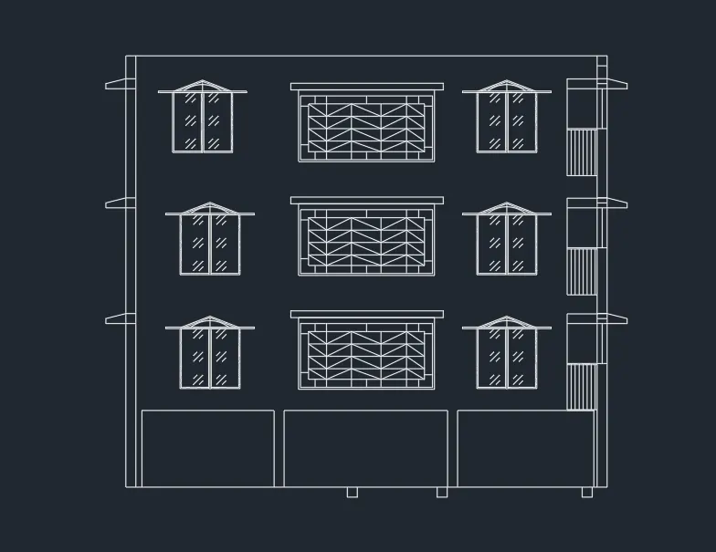
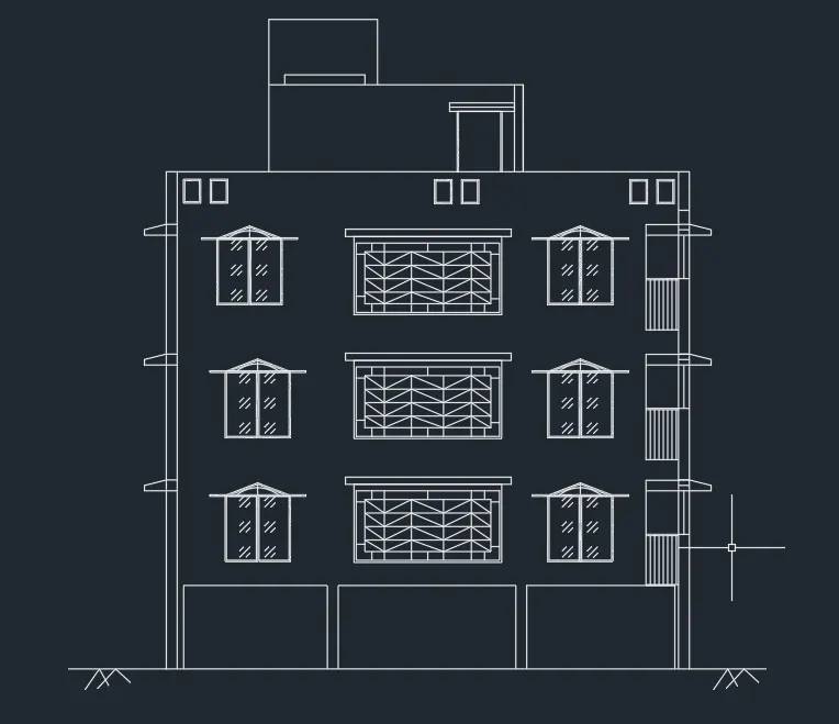
RESULT:-
The elevation of the plan created and the hatch in the walls, doors, windows, and other architectural elements is completed by using autocad.
Q3.
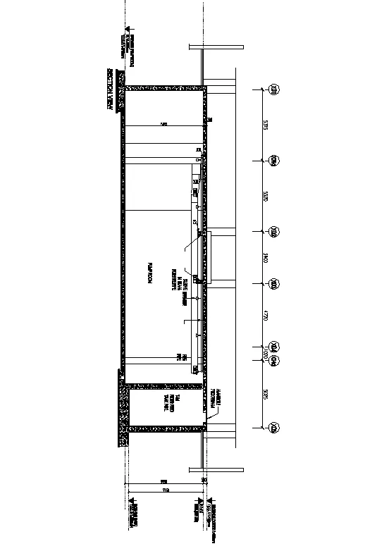
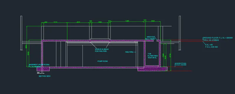
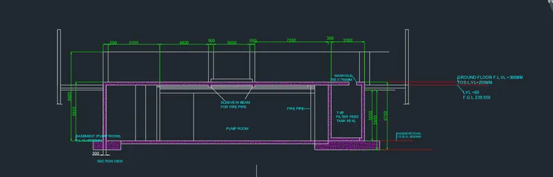
AIM:-. Create the section view of an industrial building as shown in Figure. Provide appropriate hatches and dimensions wherever required. Also, provide annotations to the drawing.
COMMANDS USED:-
- Limits command
- X-Line command
- Line command
- Offset command
- Hatch command
- Dimlinear command
- Dimstyle command
- Units command
- Extend command
- Fillet command
- Trim command
- Join commandi
- Line weight command
- Line type command
- Object snap command
- Rectangle command
- Zoom command
PROCEDURE:-
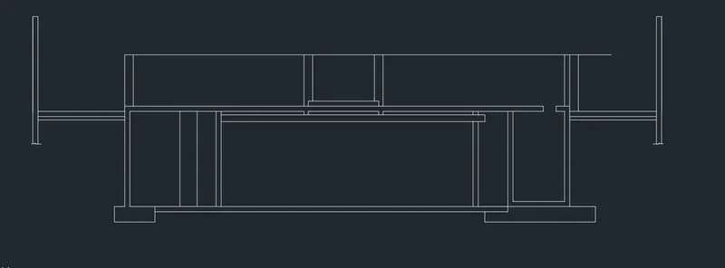
1. LAYERS - Creating layer for dimmension , exterior, wall, duct, springler , and set diffrent color to particular layers.
2. EXTERIOR WALL - For creating exterior wall taking line tool and start a line create a vertical line having length 5550mm after that continue provide length 300,5315,5320,3900,4720,1020,5025,300 after providing length in x direction create a line having 5550 in -y direction. and attch to start point of the line and create another line in both corner having 300mm width.
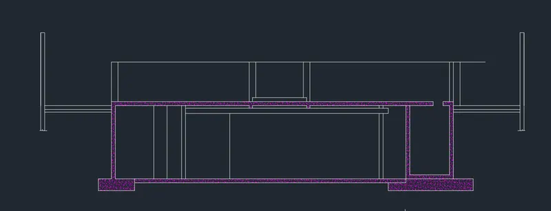
3. HATCHING - for hatching using sand and provide cyan color to the hatching. for bottom p.c.c. use one color gradient.
4. column foundation - in the both end create a column foundation by using line tool and and hatching inside the foundation by sand.
5. taking line tool and create a 3000mm horizontal line in -x direction and create 5000x100 rectangle in left side.
6. BASEMENT - FOR showing basement using hidden line having dark orange color.
7. IN top in bottom side create a 100 width rectangle create by taking line tool .
8. for creating a duct taking a line tool and create 200mm width create as a same line as create before same distance.
9. springler - creating springler taking a rectangle tool nd create a small rectangle and create a small elipse from bottom side of the rectangle and provide a pink color layer for showing a diffrent part.
10. sleeve - provide eleeve in the beam for fire taking rectangle tool a create a sleve for fire pipe. and triming unneccesary lines.
11. FILTER FEED TANK - creating a filter feed tank taking offset tool in last end and provide 3000mm offset in -xdirection. againg provide 300mm offset and hatching inside the wall. and its top provide a manhole having 750x750 size.
12. taking a line tool and create as a same procedure yet we created in start point and provide line 3000mm in x direction and create a rectangle having 5000x100 size.
13. HIDDEN LINE - hidden line is only use to show the basement plan ground and floor level its having a red orange color.
14. TEXT - For creating text using multiline text and change multiline text by new roman and use bolded charecter for adding a text.
15. DIMENSIONS - for providing a dimension using dimlinear and after that taking dimcontinue tool for continues dimension.
16.HATCH:- Use the HATCH Command to show hatch in the drawing.
Hatching of walls
Go to the Draw panel on the Home tab. Find the hatch icon in the bottom right corner.
In "Hatch creation” tab. Go to its Properties panel and choose the Hatch type that you would like to insert. Here pattern type was used for hatching. 8
In hatch settings "create separate hatches" options was selected, so that each entity will remain as an individual if any correction was to be made, else it would have to be done from first.
Pick points options was was to hatch the area. The “Pick Points” will determine a boundary around the specified point.
After filling the area, hit “Enter” to apply the hatch.
A new layer is now created, named as texts and a suitable colour is selected and this layer is made as the default.
Now using the MTEXT all the texts was made and the following image is obtained.
A new layer is now created, named as Dimensions and a suitable colour is selected and this layer is made as the default.
Now using the Dimlin the dimensions was plotted and the following image is obtained
RESULT:-
RESULT:-
The section view of an industrial building is completed by using autocad.