Creating Bar Bending schedule, Different Door types, and Creation of standard drawing templates using AutoCad
Q1.
AIM :-
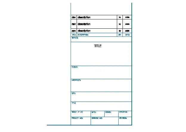
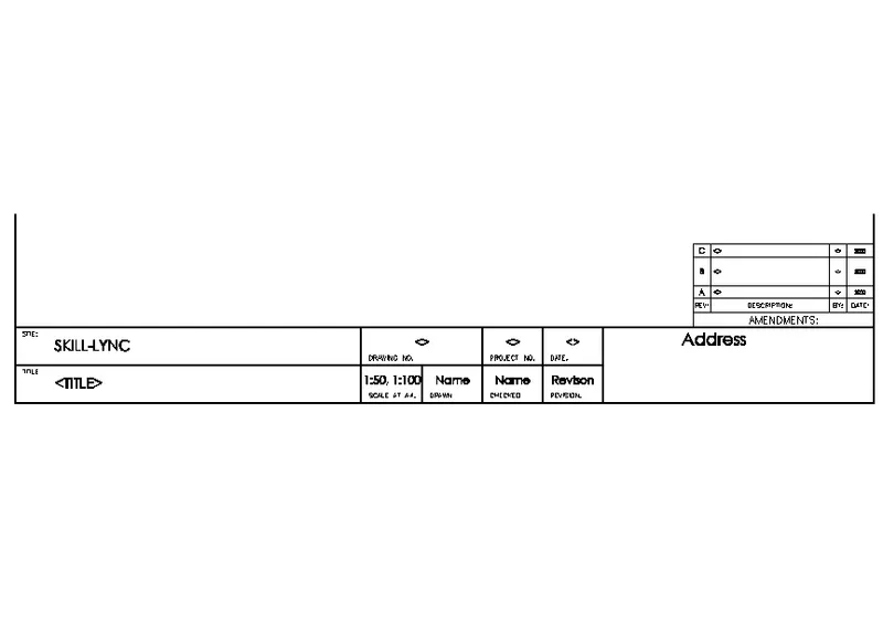
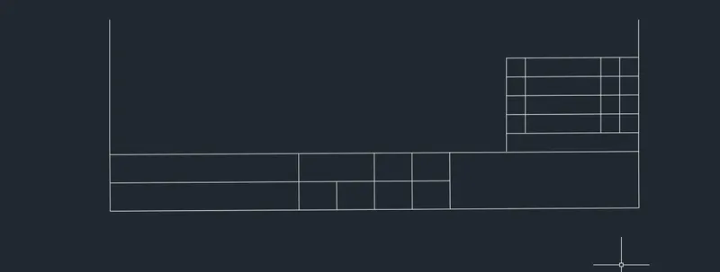
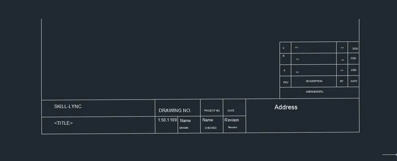
Create the templates as shown in Figures. Take the size of the title block as per industry standards or you can assume it as per the size of the paper. Use text and attributes wherever required. After creating the title block you need to save it as a block with names: Custom1_titleblock and Custom2_titleblock, respectively.
PROCEDURE :-
Step 1 - Custom1_titleblock
- To create a Layer
- In the Layer Properties Manager, click New Layer.
- A layer name is added to the layer list.
- Enter a new layer name as TABLE by typing over the highlighted layer name.
- Select a suitable colour for that layer and set this layer as the default layer.
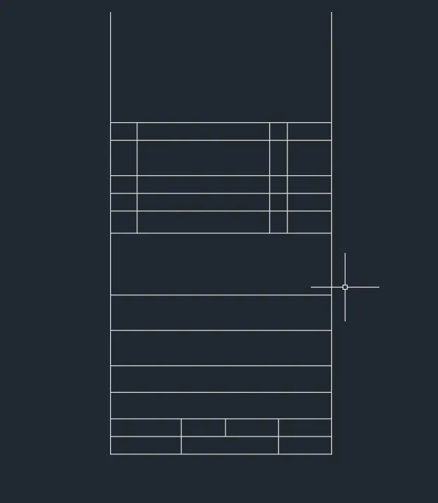
- Using the line command a table was drawn
- A new layer is now created, named as texts and a suitable colour is selected and this layer is made as the default.
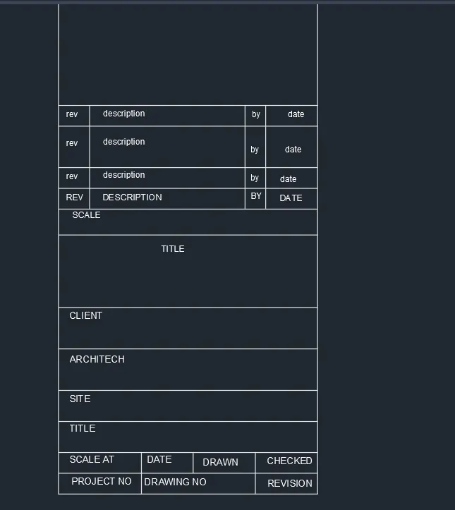
- Type ST to open the TEXT STYLE manager, TEMPUS SANS ITC font was selected and height was set to 40 and this was set as the current one
- Now using the MULTI LINE text all the text was entered at the positions as required
RESULT :-
Custom2_title block :-
- To create a Layer
- In the Layer Properties Manager, click New Layer.
- A layer name is added to the layer list.
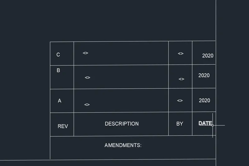
- Then create the drawing as per the drawing using line and offset coomand.
- Use MTEXT command to insert the text in the drawing.
- Use diffrent text size for different texts.
- Then create the block named custom2_title block.
RESULT:
The Tamplates of title blocks was now completed by using autocad.
Q2.
AIM:
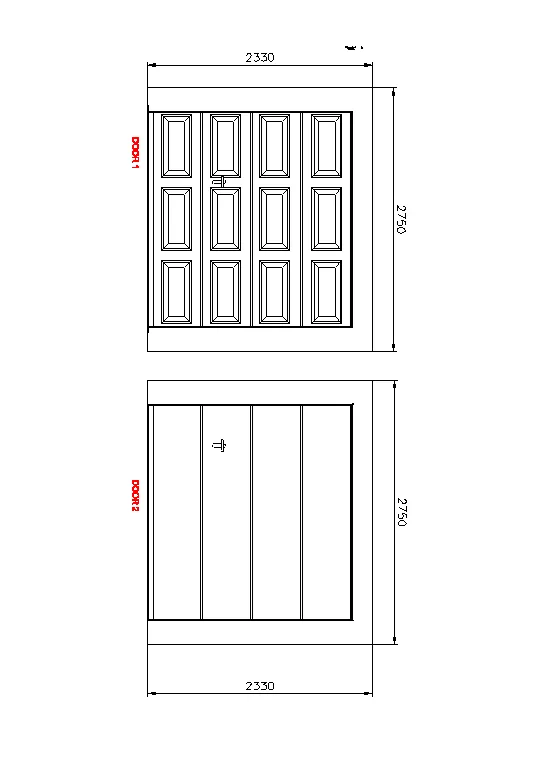
Create the doors type for warehouse as shown in the Figure. You need to create each door type as per standard size or given dimensions. Create the blocks of this door type after creating them.
PROCEDURE:-
Door-1 :-
- Draw the rectangle of size 2330 X 2750 mm.
- Then offset the lines with 50 mm.
- After dividing the line in 4 parts, create the frames of the drawings.
- Then create the panels in between the panels.
- Then copy the panels in different frames.
- For making block, Type B in command line and select BLOCK command.
- Then select Pick Point the select the object and name the block.
- So the block is created.
- Name the block as D1.
- The handle of the door was created using the line command.
- A new layer is now created, named as DIMENSIONS and a suitable colour is selected and this layer is made as the default.
- The dimensioning is done using the DIMLIM command and the final image of door is as follows
RESULT:-
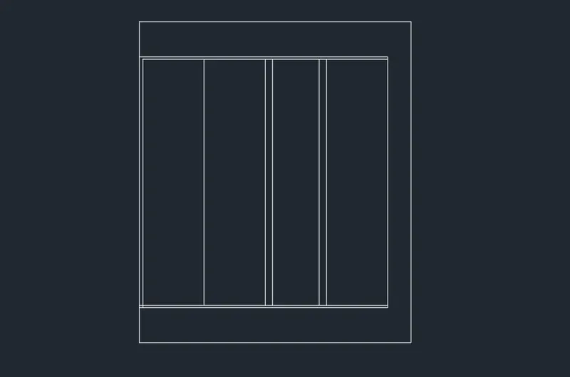
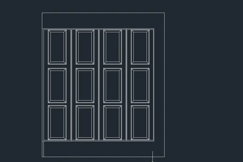
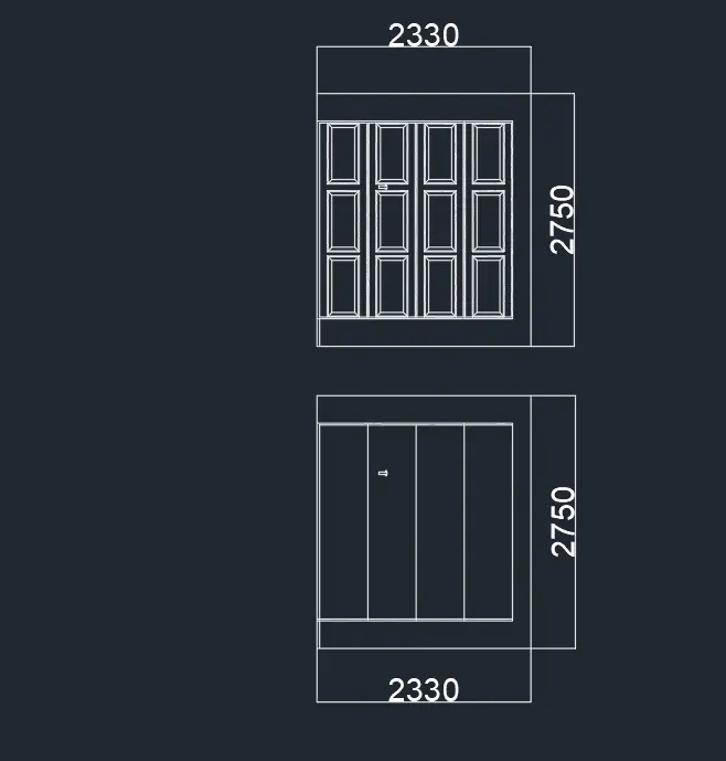
Door-2 :-
- Draw the rectangle of size 2330 X 2750 mm.
- Then offset the lines with 50 mm.
- After dividing the line in 4 parts.
- For making block, Type B in command line and select BLOCK command.
- Then select Pick Point the select the object and name the block.
- So the block is created.
- The handle of the door was created using the line command.
- A new layer is now created, named as DIMENSIONS and a suitable colour is selected and this layer is made as the default.
- The dimensioning is done using the DIMLIM command and the final image of door is as follows
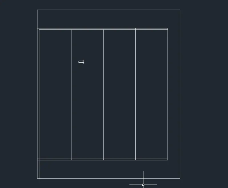
RESULT:
The doors type for warehouse is now completed by using autocad.
Q3.
AIM:-
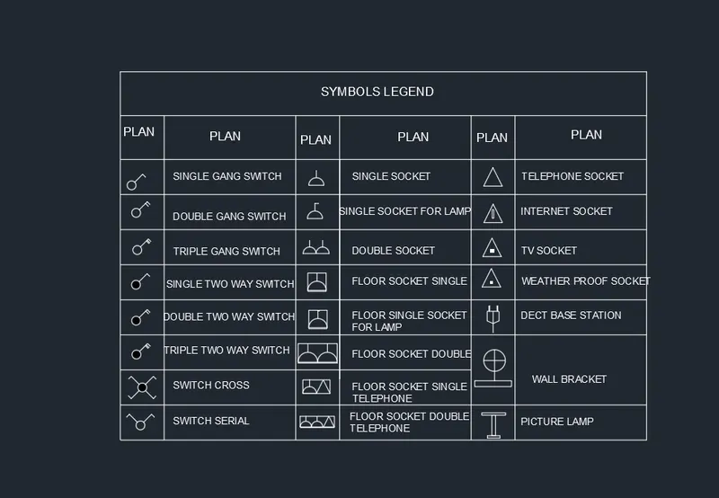
Create each symbol as a block with the name given in the legend. After creating the blocks arrange them in the legend as shown in the Figure.
PROCEDURE:-
- In the Layer Properties Manager, click New Layer.
- A layer name is added to the layer list.
- Enter a new layer name as ElECTRICAL LEGENDS by typing over the highlighted layer name.
- Select a suitable colour for that layer and set this layer as the default layer.
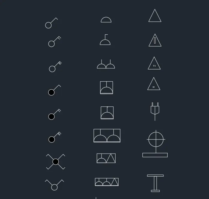
- Now all the electrical legends was drafted using the line, rectnagle,circle, and Hatch command.
- All of these are simple geometries and can be made easily.
- The TABLES layer which was created was made default layer.
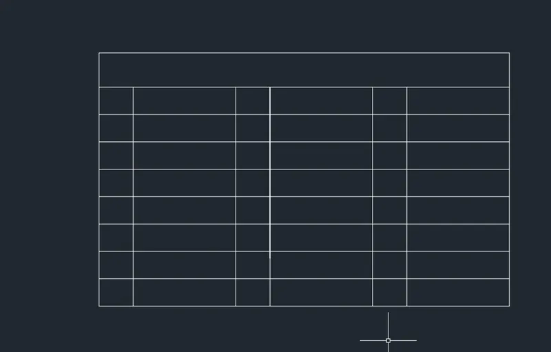
- Using the line and rectangle command a table appropriate for filling filling details was drawn as shown.
- The TEXTS layer which was created was made default layer.
- Now using the MULTI LINE text all the headings was entered at the positions as required
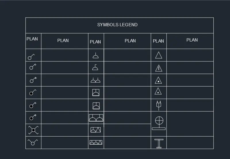
- Type I and press enter to insert the blocks.
- Select the first block which you want to enter and place it under the plan column as shown
- Now create the rectangle of 10 rows and 6 columns.
- Place each blocks in respective rows and columns
- In the similar manner as above all the other blocks was placed and their feilds was also made as shown.
RESULT:-
RESULT:
The symbol legends as a block with the name given in the legended is completed by using autocad.
Q4.
AIM :-
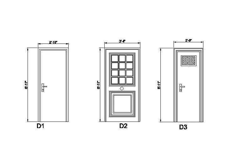
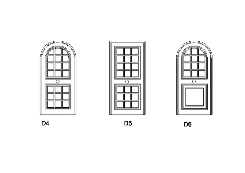
Create the door type for residential building as a block. Save the name of the blocks as type. Use given dimensions or assume dimensions as per industry standards.
PROCEDURE :-
D1 :-
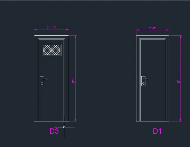
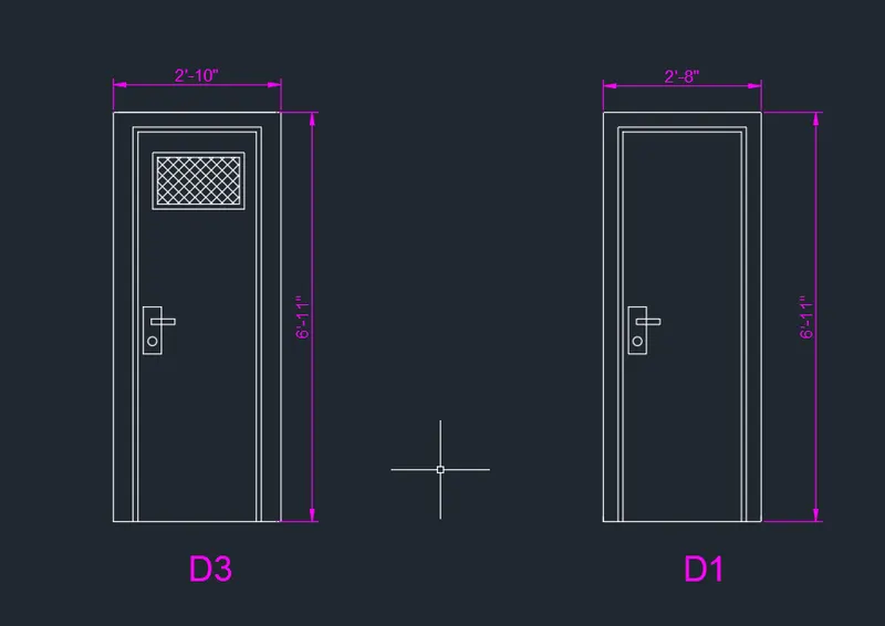
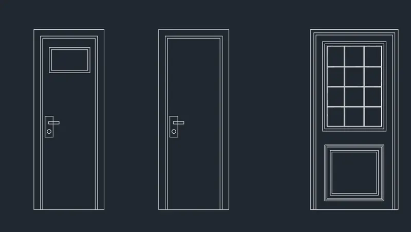
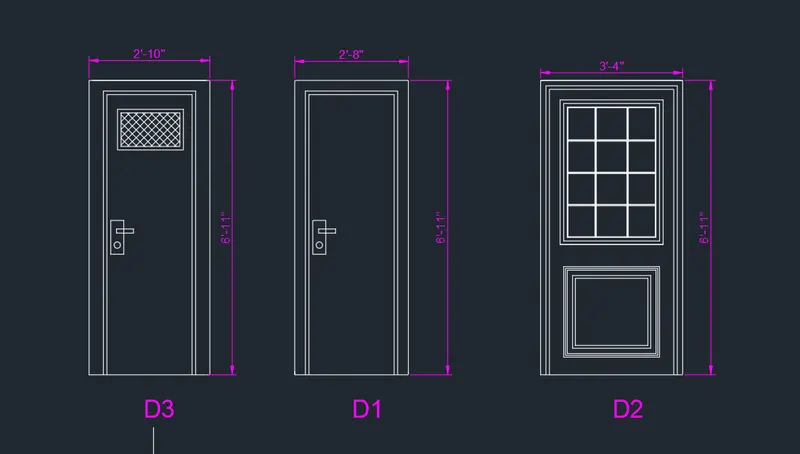
- Draw the Rectangle of size 2'10" X 6'11".
- offset the lines with 1.5" and 1" to make the Frame.
- Draw the lock by Rectancles and Circle.
- Annotate it with dimensions.
- Create the Block of the door.
- Name- D1, Select the Object, Pick Point, OK.
D2 :-
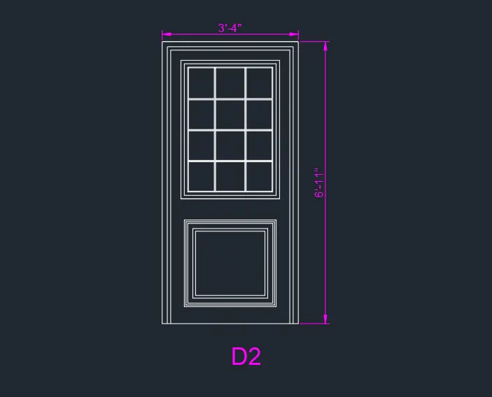
- Draw the Rectangle of size 3'4" X 6'11".
- Then draw the rectangle panel and offset it with 1" and 1.5".
- Draw the squares in the panel and increase the lineweight of squares.
- Draw the Rectangle below the rectanular panels.
- and offset the rectangles.
- Place the circle of 3" in between both the panels.
- Annotate it with dimensions.
- Create the Block of the door.
- Name- D2, Select the Object, Pick Point, OK.
D3 :-
- Draw the Rectangle of size 2'9" X 6'11".
- Offset the lines with 1" and 1.5" and make Panels.
- Draw the rectangle of 1.5" and 9".
- Hatch the rectangle by relative scale.
- Draw the lock by Rectancles and Circle.
- Annotate it with dimensions.
- Create the Block of the door.
- Name- D3, Select the Object, Pick Point, OK.
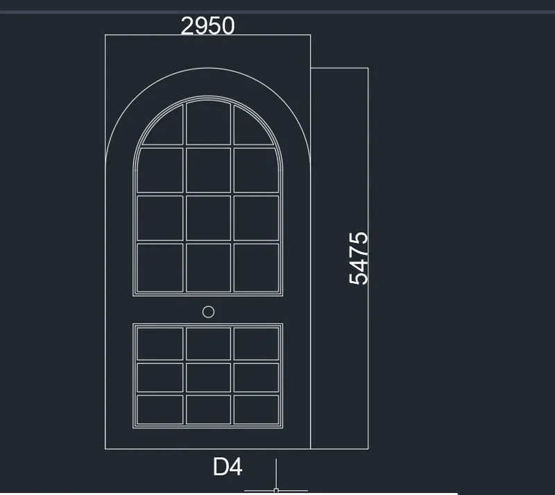
D4 :-
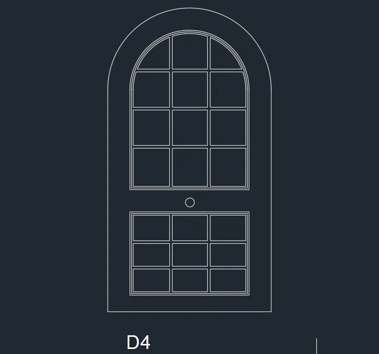
- Draw the line of size 3'9.5" X 8'3.6".
- Draw the Arc of length 3'9.5".
- Offset the arc by 1" and 1.5" for panels.
- Draw the Rectangle below the rectanular panels.
- Place the rectangles in the rectangle.
- And offset the rectangles.
- Place the circle of 3" in between both the panels.
- Annotate it with dimensions.
- Create the Block of the door.
- Name- D4, Select the Object, Pick Point, OK.
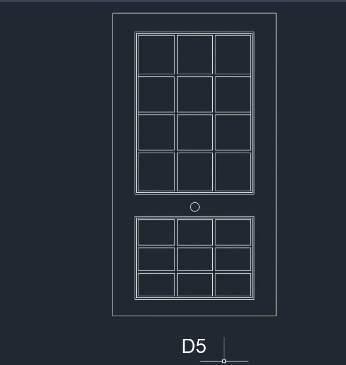
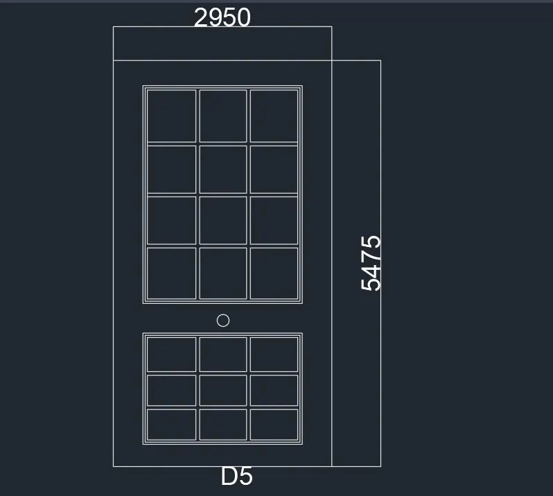
D5 :-
- Draw the Rectangle of size 4' X 8'3.6".
- Offset the lines with 1.5" and 1" to make the Frame.
- Draw the squares in the panel and increase the lineweight of squares.
- Draw the Rectangle below the rectanular panels.
- and offset the rectangles.
- Place the circle of 3" in between both the panels.
- Annotate it with dimensions.
- Create the Block of the door.
- Name- D5, Select the Object, Pick Point, OK.
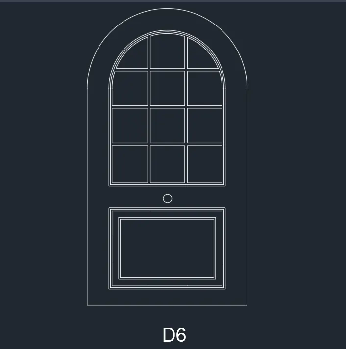
D6 :-
- Draw the line of size 3'9.5" X 8'3.6".
- Draw the Arc of length 3'9.5".
- Offset the arc by 1" and 1.5" for panels.
- Draw the Rectangle below the rectanular panels.
- And offset the rectangles.
- Place the circle of 3" in between both the panels.
- Annotate it with dimensions.
- Create the Block of the door.
- Name- D4, Select the Object, Pick Point, OK.
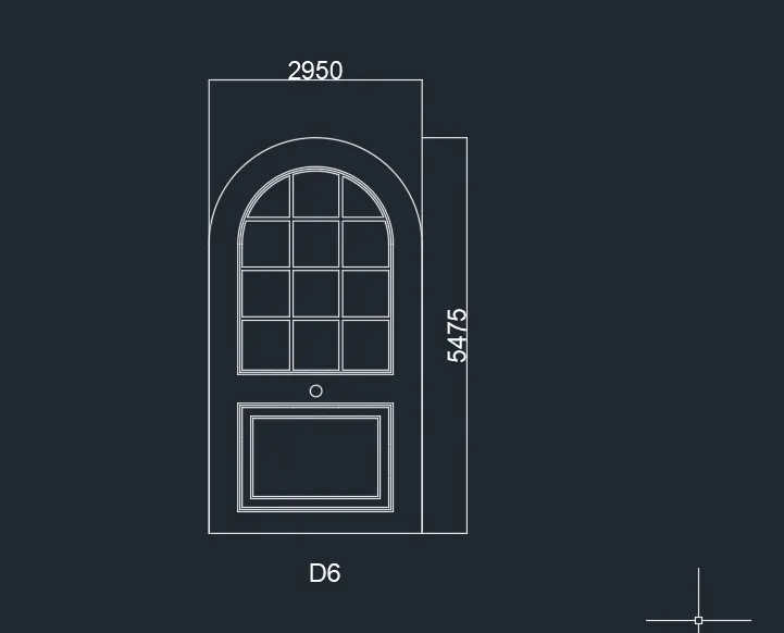
RESULT :-
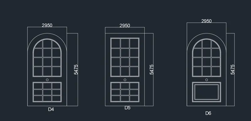
RESULT:
The door type for residential building is now completed by using autocad.
Q5.
AIM :-
Create each shape as a block as shown in the Figure. Save the block and insert them on the table as shown in the Figure
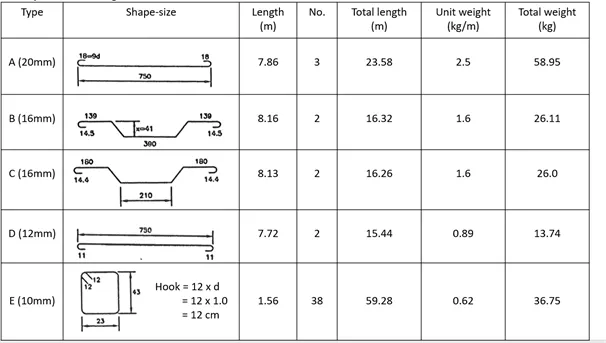
PROCEDURE:-
- In the Layer Properties Manager, click New Layer.
- A layer name is added to the layer list.
- Enter a new layer name as BEAMS by typing over the highlighted layer name.
- Select a suitable colour for that layer and set this layer as the default layer.
- The beams was cretaed easily by using the line,start end direction arc, rectangle and fillet command as shown
- The TEXTS layer which was created was made default layer.
- Now using the MULTI LINE text all the texts was entered at the positions as required
- The DIMENSIONS layer which was created was made default layer.
- Using the DIMLIM command all the required dimensions was marked as shown.
- The TABLES layer which was created was made default layer.
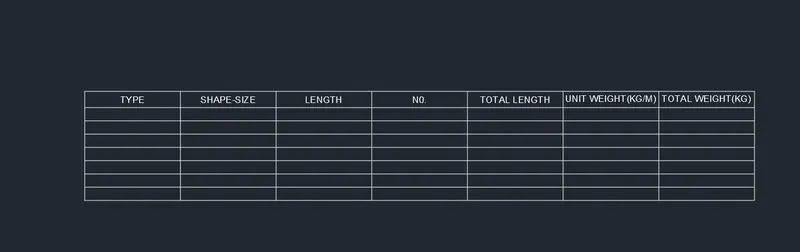
- Using the line and rectangle command a table appropriate for filling filling details was drawn as shown.
- The TEXTS layer which was created was made default layer.
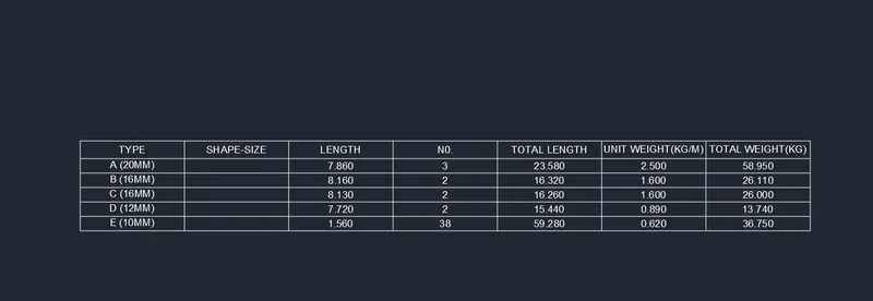
- Now using the MULTI LINE text all the headings and all text was entered at the positions as required.
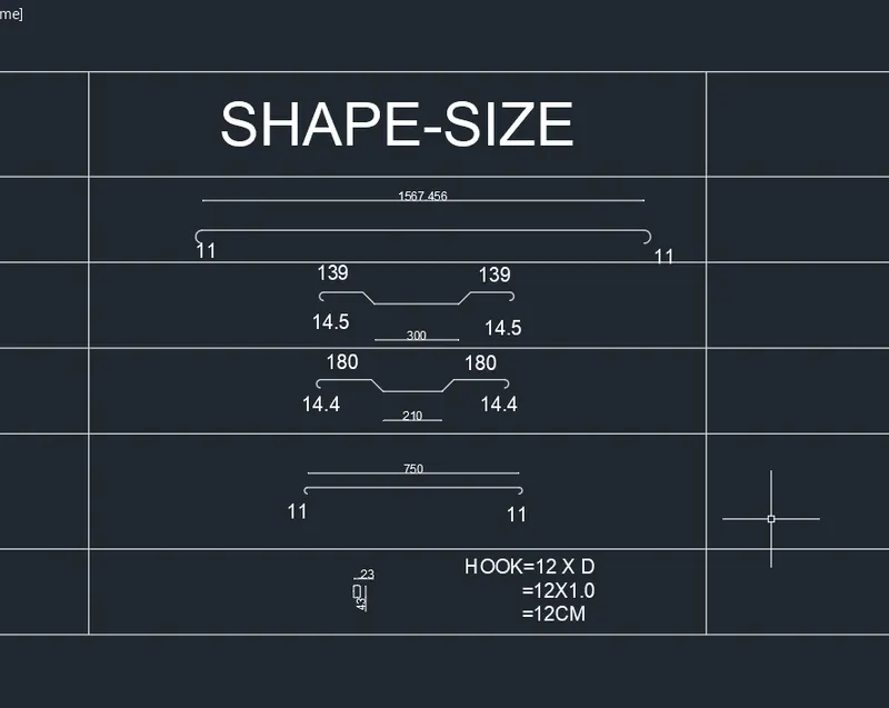
- Also all the beams was placed under shape-size column using the insert block option.
1. A(20 mm)
- Draw the line of 750 mm in length.
- Create the arc bend at 1 side and mirror it at another side.
2. B(16 mm)
- Draw the straight line of 300 mm.
- Then draw the line at 45 degree and 41 mm in size.
- Then draw the line of 139 mm from 41mm line.
- Create the arc bend at 1 side.
- Mirror whole drawing at another side at 180 degree.
3. C(16 mm)
- Draw the straight line of 210 mm.
- Then draw the line at 45 degree and 41 mm in size.
- Then draw the line of 180 mm from 41mm line.
- circle radius to take 14.4.
- Create the arc bend at 1 side.
- Mirror whole drawing at another side at 180 degree.
4. D(12 mm)
- Draw the line of 750 mm in length.
- Create the arc bend downward side at 1 side and mirror it at another side.
5. E(10 mm)
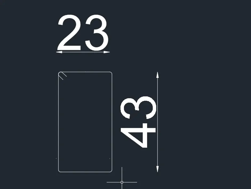
- Draw the rectangle of 23 mm X 43 mm.
- Fill the fillet of radius 5 mm.
- Draw 2 lines of 12 cm.
- The TABLES layer which was created was made default layer.
- Using the line and rectangle command a table appropriate for filling filling details was drawn as shown.
- The TEXTS layer which was created was made default layer.
- Now using the MULTI LINE text all the headings was entered at the positions as required.
- Type I and press enter to insert the blocks.
- Select the first block which you want to enter and place it under the plan column as shown
RESULT :-
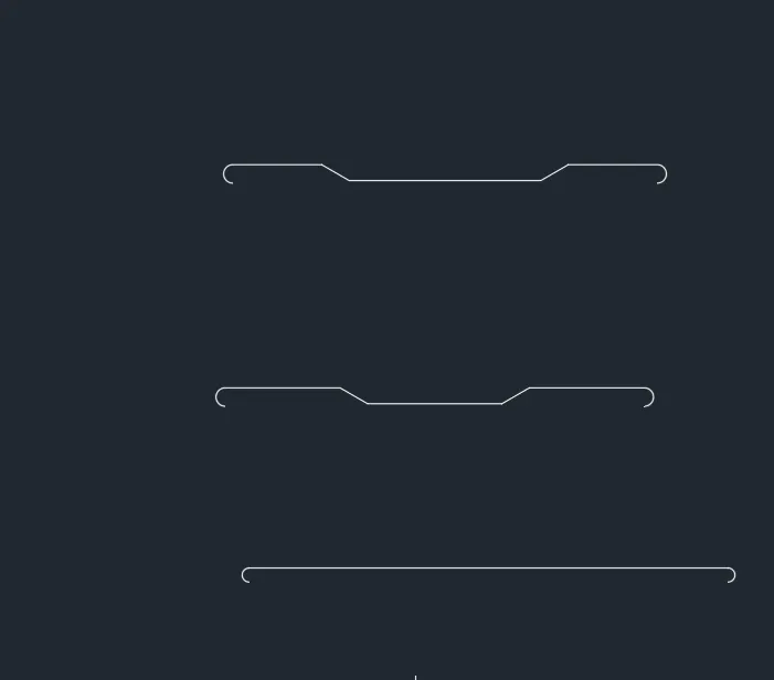
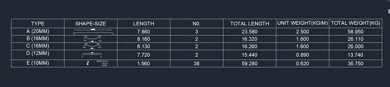
RESULT:
To create the bar bending schedule and insert it as a block was completed drawn by using autocad.