Structural Modelling using Etabs 2018
AIM: To design the structural model that comply with provisions of IS 1893 and IS 13920 in seismic zone V and run a modal response spectrum analysis and check analysis results of the etabs model for inter-storey drift requirements, vertical & planar irregularities, minimum shear wall requirements,maximum axial load ratio for column and shear walls, effective moment of inertia for beams
and columns etc.,
INTRODCUTION:
- ETABS is an engineering software product for the analysis of concrete shear walls and concrete moment frames. It is mainly used for static and dynamic analysis of multi-storey frame and shear wall buildings.
- It mainly consist of modeling tools and templates, code-based load prescriptions, analysis methods and solution techniques, all coordinate with the grid-like geometry unique feature.
- Main advantage is that with the help of similar storey concept creation of 3D model is very easy and quicker. If the storey’s are similar then the model generation time can be reduced multiple time through similar storey concept.
PROCEDURE:
step1-Initial setup of grids and floors.
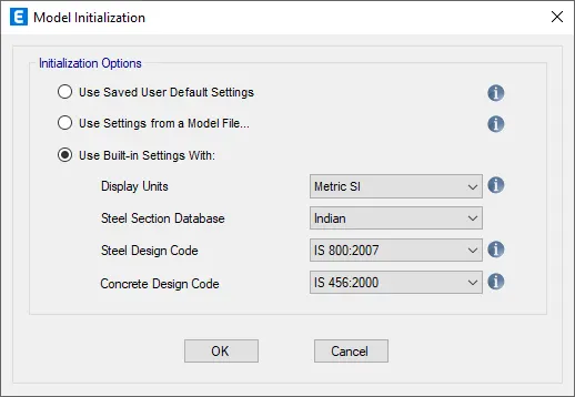
- open th etabs file,new model>set the model initialization to indian codes and metric unit.
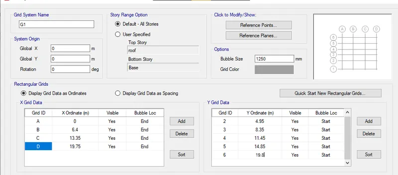
- from new model quick template set both grids and storey to custom.
- edit the grid pattern accordinag to column placement(6x4).
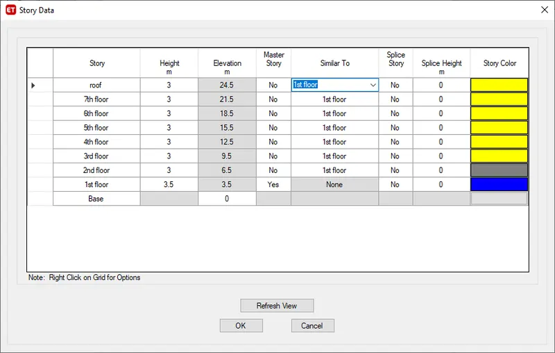
- set the storey total of parking(3.5m,3+0.5 for column extends below the soil depending on strantion pentration test results)+7th floor(3m) and roof.
step 2-define material properties
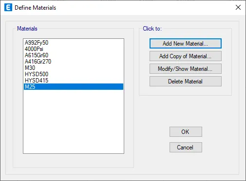
- define>material properties>add new material.
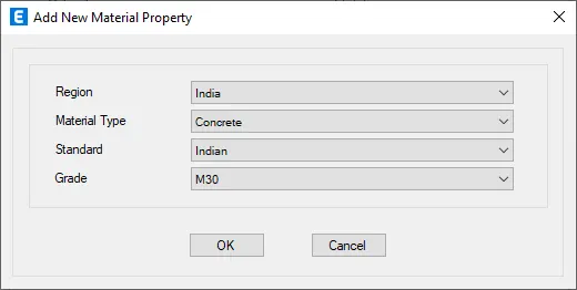
- set region as India>material as concrete>grade as M30.
- simialry repeat the same to define M25.
- for steel,set the type as rebar and select grade as HYSD500.
- repeat the same for HYSD415 steel grade.
step 3- define the section properties
- define>section properties>frame section>add new properties.
- select the rectangular concrete>beam 250x450>M30 grade>reinforcement>select only beam and select grade of steel for longitudinal and shear reiforcement.
- also reduce the beam torsional constant as 0.001 and moment of inetria for seismic loads as 0.35.
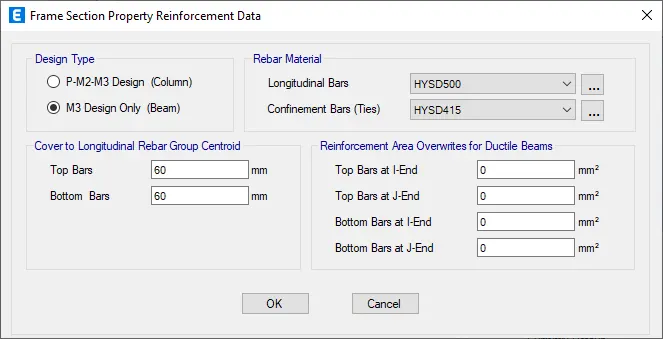
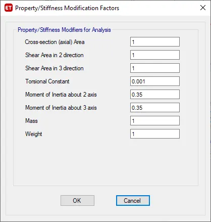
- repeat the same for beam 300x500.
- again select rectangular frame>column 400x400>select column and set the reinforcement details and set number of bars with diameter along with reduction in moment of inertia as 0.7.
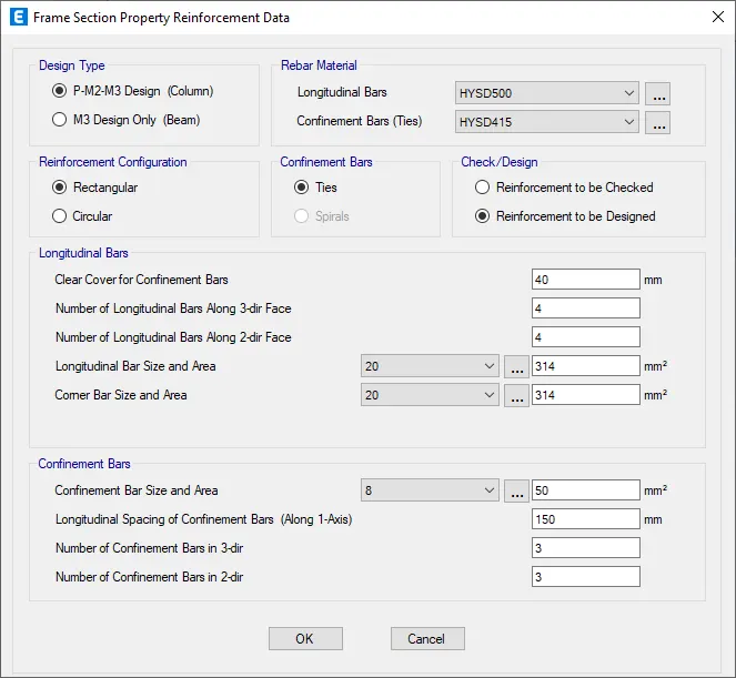
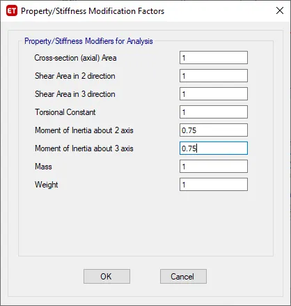
- similarly repeat the same for 400x600.
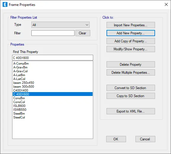
- define>section properties>slab section>add new propeties.
- set grade as M25 and modleing type as membrane for btoh 115 and 125mm slab thickness.
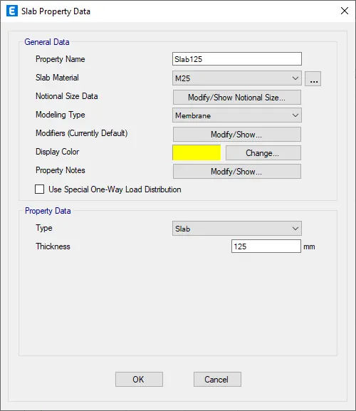
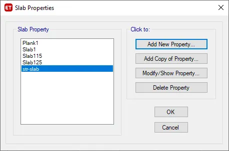
- define slab for staircase of thicknes 200mm.
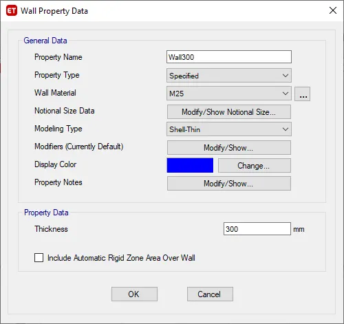
- final property is wall,define>section properties>wall section.
- define for wall for thickness 250 and 300mm,keep grade as M25 and modeling type as shell-thin.
step 4-geometric modelling
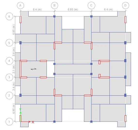
- first element to define is column,click on quick draw column>selet the type>click on required grid to place.
- once column placed,select quick draw beam and click on required grid lines to place.
- for secondry beams grid,use replicate,move,mirror and break tool to make.(make sure beam are not closely placed to walls).
- to add shear wall use draw wall command.
- last to add slab,for staircase(t=200mm),remaining 125mm thick slab.
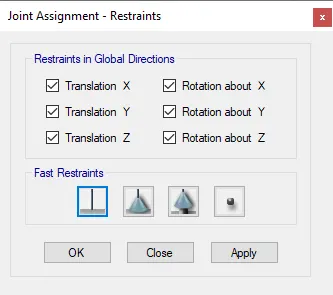
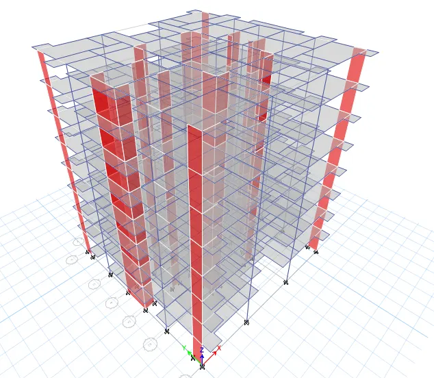
- lastly got o base floor >select joints and assign restraint as fixed.
step 5- define the loads
go to define>load cases>add all gravity loads and earthquake load.
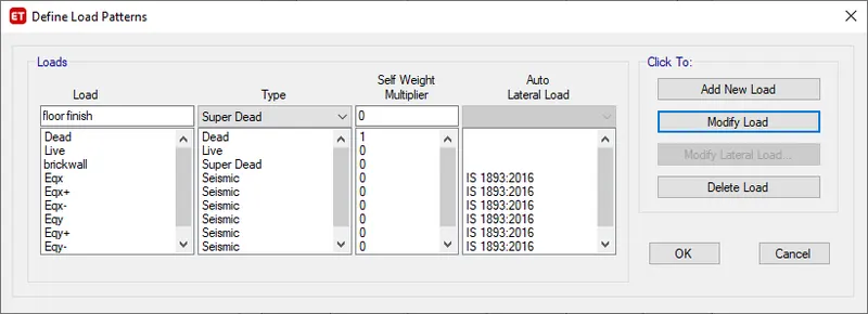
for defining earthquake,example Eqx-
select direction and eccentricity as x-direction.
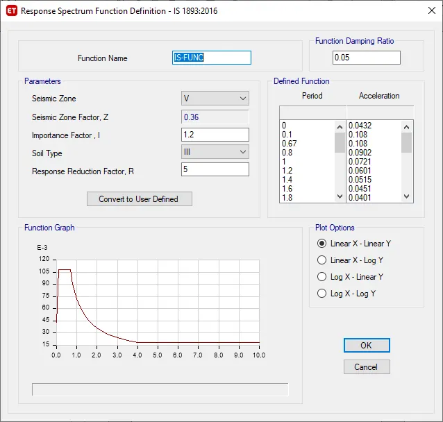
assuming its a dual system(shear wall+MRF),R=5.
seismic zone is 5,Z=0.36.
lets take soil type as 3.
as per IS 875,tale 2-importance factor for residential building with less than 200=1
in order to calculate fundamental time period T,IS 1893 clause 7.6.1
T=0.09*h/`sqrtd`,h=24.5m and d on both side is around 20.
T=0.09*24.5/`sqrt20`=0.5 sec.
step 6- assign the loads.
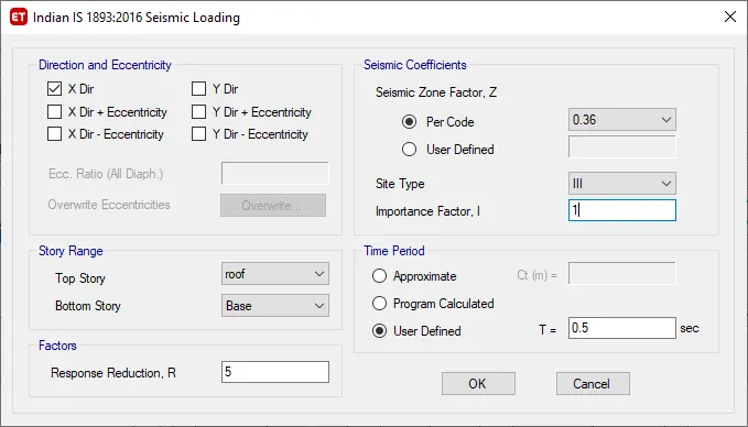
- select the frame on which brickwall falls by referring architectural plan and provide 3.5kn/m^2(strength of brick*cross section+plastering).
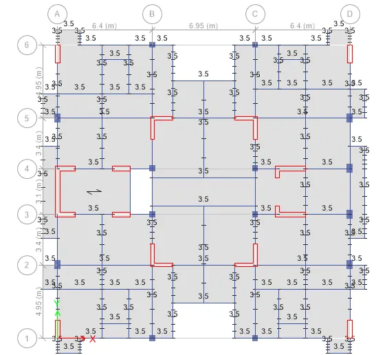
- simialry select slab for which live load to be assigned.
- as per IS 875,live load for residential building 2kN/m^2 for rooms,bathrooms etc., and for staircase,liftcore and balcony 3kN/m^2.
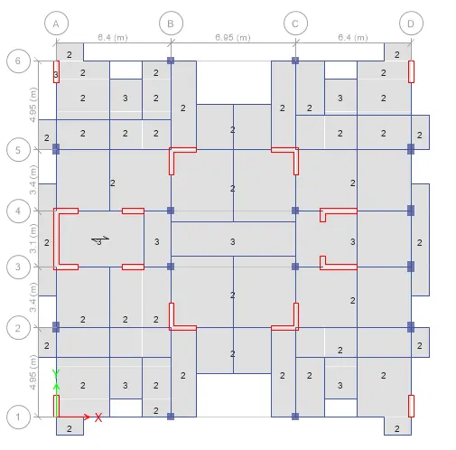
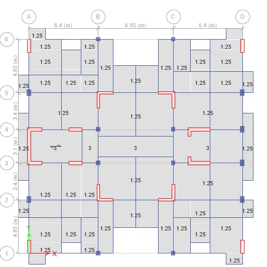
- simailry select slabs to assign floor finish which is 1.25kN/m^2 for rooms and bathrooms and 3kN/m^2 for staircase,balcony.
- design live load reduction factor referring to Is 875 code book.

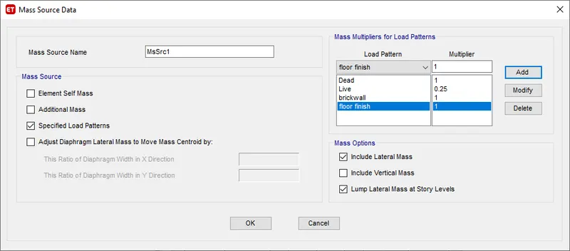
- assign mass source to apply earthquake load,define>mass cource and define one
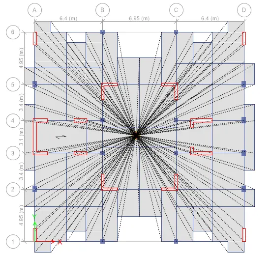
- select al slabs>assign>shell>diaphragms>D1.
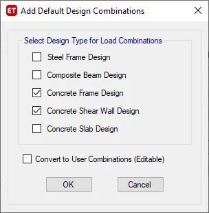
- define the load combination as per default for both frame and shell.
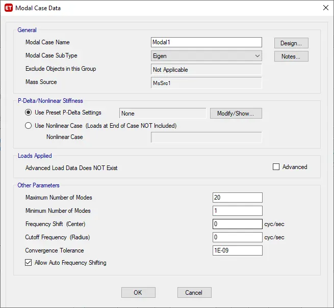
- define the modal cases for spectrum analysis,set max modal number as 20.
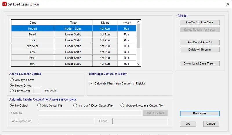
- set the load case run,here both equivalent lateral force analysis and spectrum analysis is done together.
- lets defien new function as per IS 1893 for response spectrum analysis.
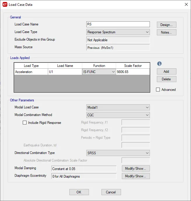
- define two more load cases for response spectrum analysis and set default scale factor initially.
step 7-analyses
- analyze>check model>see for overlapping.

- no error >run analysis.
step 8- to obtain new scale factor
- once analysis is done,go to dispaly>show tabel>structural output>base shear.
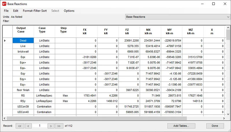
- as per IS 1893-clause 7.7.3,design base shear estimated shall not be less than design base shear calculated-if so then scale factor shall be mutlipied by calculated base shear/estimated base shear.
- here for RSx,ratio is 2.1 and RSy,ration is 2.5.
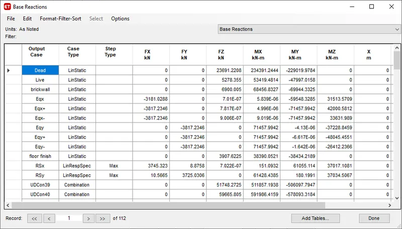
step 9- check for modal number.
- dispaly>show table>modal participating ratio.
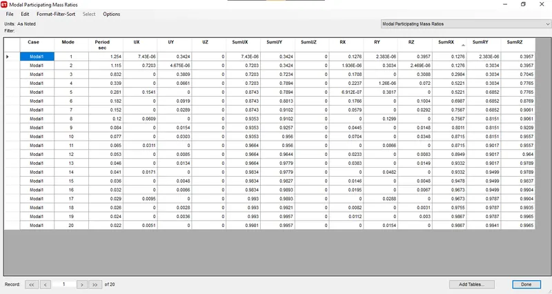
- as per IS 1873 clause 7.1,the natural period corresponding to fundamental torsional mode of oscillatio should not be greater than sum of two fundamental translational mode of oscilation(Tx+Ty>Txy)-from table 1.25+1.115=2.365>0.832.hence no torsional irregualrity.
- IS 1873-clause 7.1,table 6 the frist three model contribution should be more than 65% of mass participation factor in each principal plan direction.Here it is 0.738>0.65.
- under same table,the fundamental lateral natural period of building in two principal plan direction should differ by atleast 10%.Here Tx=1.254 and Ty=1.115,differ by 12%,hence conclude that building is regular in mode of oscillation in two principal plan direction.
- from modal number,maximum required is 13 number as it capture more than 90% of mass in all 6 degrees of freedom.
step 10- storey response plot.
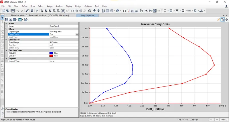
display>storey response plot>set to maximum storey drift>Eqx as load.
it is obserevd that value is within 0.004,hence ok in x-direction.

it is observed that value range in 0.0046 in y-direction,building to be made little more stiffer by adding additional column/shear wall.
step 11- base shear check
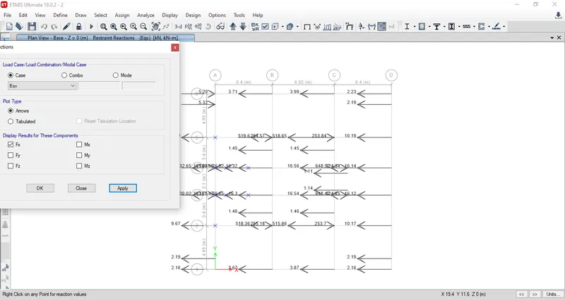
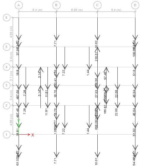
click on load display>load type as Eqx>show Fx load.
- code states that shear load should take atleast 80% of the load.
- to find the percentage,add of Fx divided by total Eqx base shear calculated.
- 3174/3800=83.5%>80%,provided shear wall is sufficient in x-direction.
- 3181/3800=83%>80%,provided shear wall is sufficient in y-direction ,overall shear wall is sufficient.
step 12- check if any column is under tension.
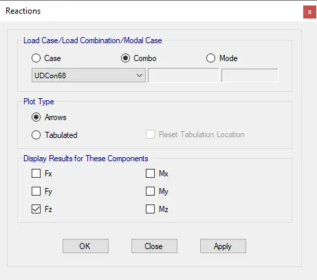
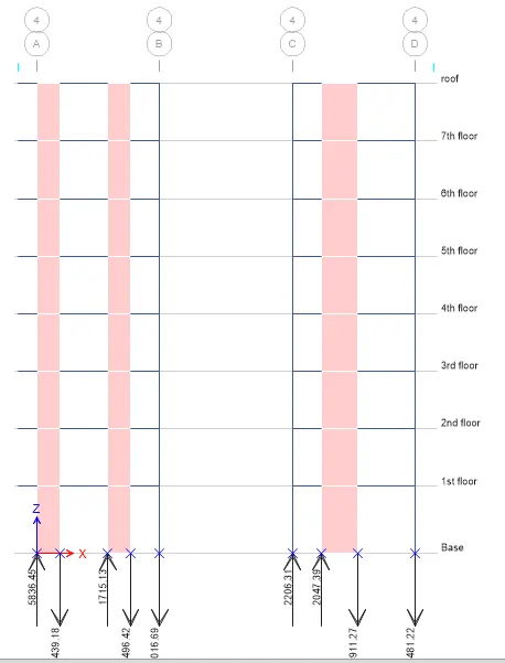
- under 3rd load condition(0.9DL),the column provided in 4b and 4d are found to be under tension.
step 13- check for aspect ration for both column and shear wall.
column-the aspect ratio should be less than 0.4.(aspect ratio=force/cross section area*fck).
lets consider for first load combination(1.5DL),force 1580kN.
aspect ratio=1580*1000/400*600*30=0.22< 0.4,hence ok.
shear wall-the aspect ration should be less than 0.28.
under same load condition,force is 7.22kN.
aspect ratio=7.22*1000/1200*300*25=0.08<0.28,hence ok.
RESULT:
- The structural model is designed for given architectural planning using etabs.
- fram model which satisfy both codal provision are analyses.
- columns,shear walls and beam are procided in possible symmetrical way without much offsets.
- analyses is done for modal number,base shear,storey drift,aspect ratio,irrgeluarity etc.,
- as per the analyses result,building is bit flexible in y-axis,as shear wall are sufficient add addiitonal column as provided in y-direction to meet the maximum storey drift limit .